Week 4- Rolling operation
Copper Sheet Rolling
Objective:
To simulate the rolling operation on the workpiece of copper alloy NL.
To find the,
Equivalent stress for the whole setup
Equivalent Plastic strain for the workpiece
Directional Deformation in the Z-axis for the workpiece
Also, to Prove that the workpiece has been displaced by 90mm.
Geometry setup:
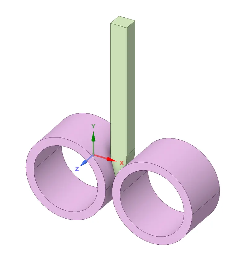
In this simulation, we have two rollers and a workpiece as we are carrying out simulations to find the workpiece's behavior. We are considering the length of the workpiece as 60mm.
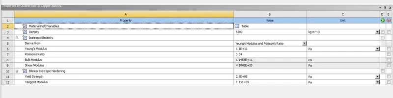
Properties of the material used:
Material for the workpiece:
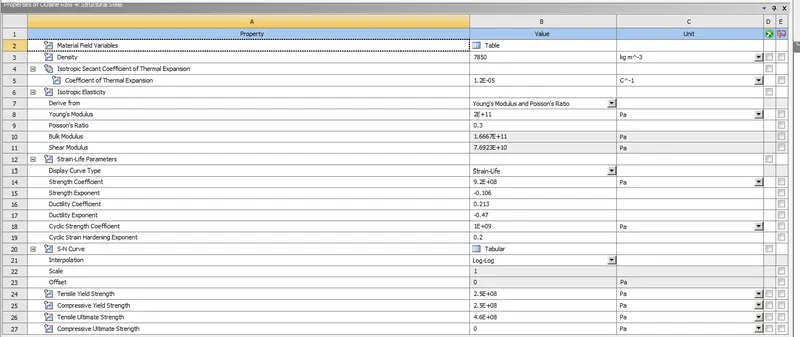
Material for the Rollers:
Mesh File:
Performed a grid dependency test with 4mm and 2mm for a better evaluation of the results.
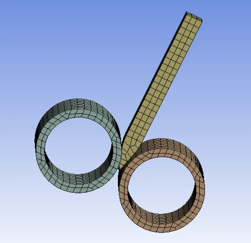
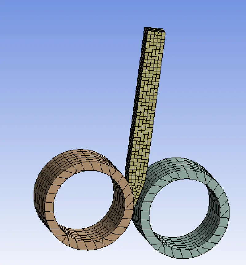
Mesh with 4mm Mesh with 2mm
Contacts Setup:
Contacts at the interface were set up for roller to the workpiece with a frictional co-efficient of 0.2mm performed by Augmented Lagrange formulation with normal stiffness factor as 0.1 and interface treatment as add offset, Ramped effects.
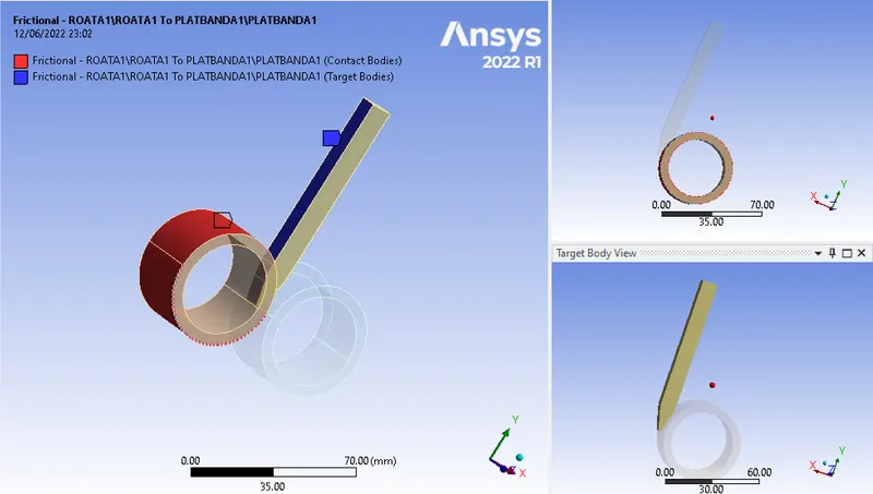
Frictional Contact 1
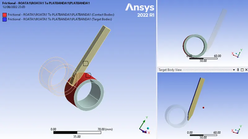
Frictional Contact 2
Joints Setup:
As we are evaluating workpiece behavior in the analysis we had to set up revolute joints for the rollers.
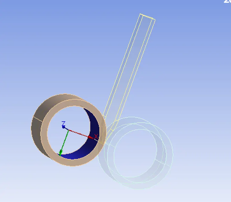
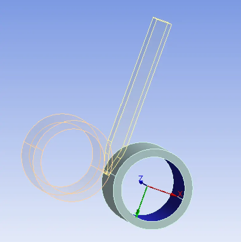
Revolute Joint setup 1 Revolute Joint setup 2
Analysis Setup:
As we are evaluating the workpiece behavior with the help of two rollers. To give the rotation for the rollers one roller is considered as clockwise and the other in an Anti-clockwise direction.
For the workpiece to displace along the Y-axis considered 14 negative values as the workpiece is moving from +Y axis to -Y-axis.
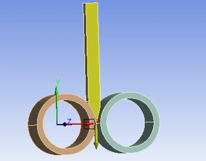
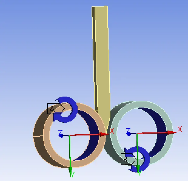
Displacement of the workpiece in Y Joint rotation setup
Simulation Results:
Total Deformation for the whole setup:
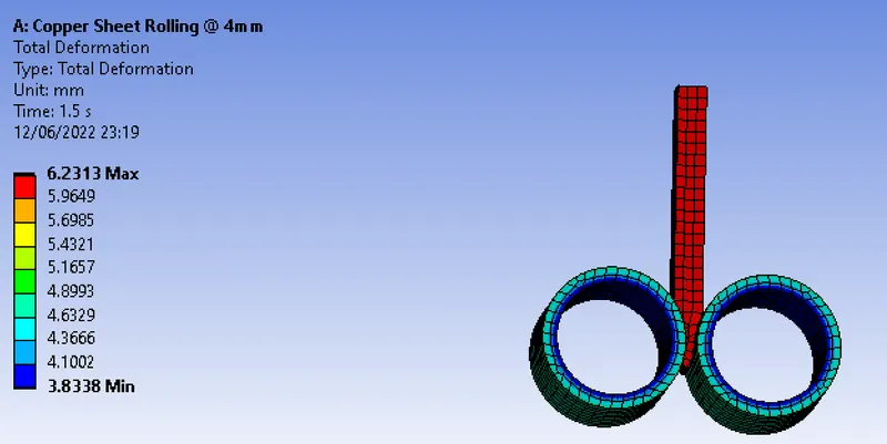
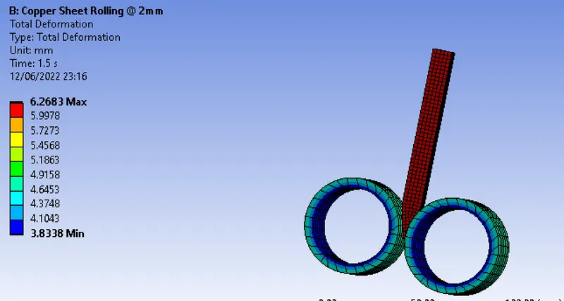
Total Deformation 4mm Total Deformation 2mm
Equivalent stress for the whole setup:
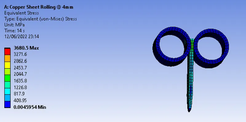
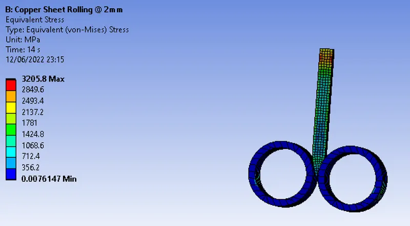
Equivalent stress 4mm Equivalent stress 2mm
Equivalent Plastic strain for the workpiece:
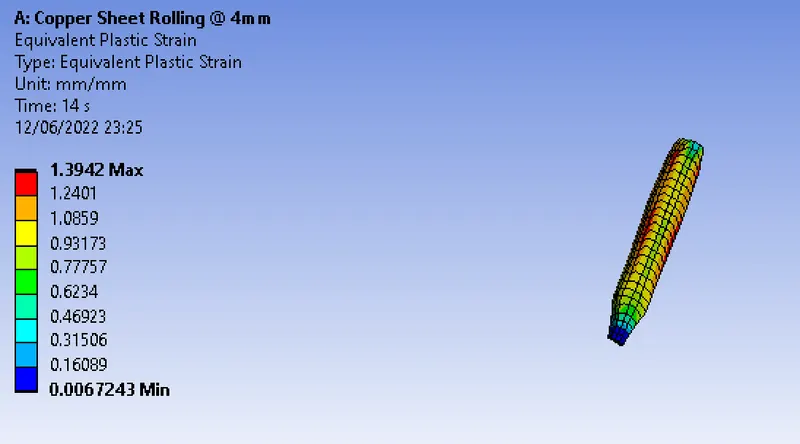
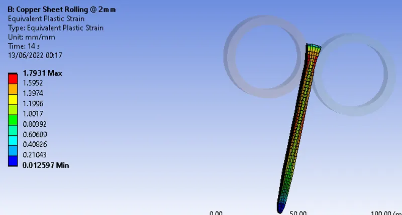
Equivalent Plastic strain 4mm Equivalent Plastic strain 4mm
Directional Deformation in the Z-axis for the workpiece
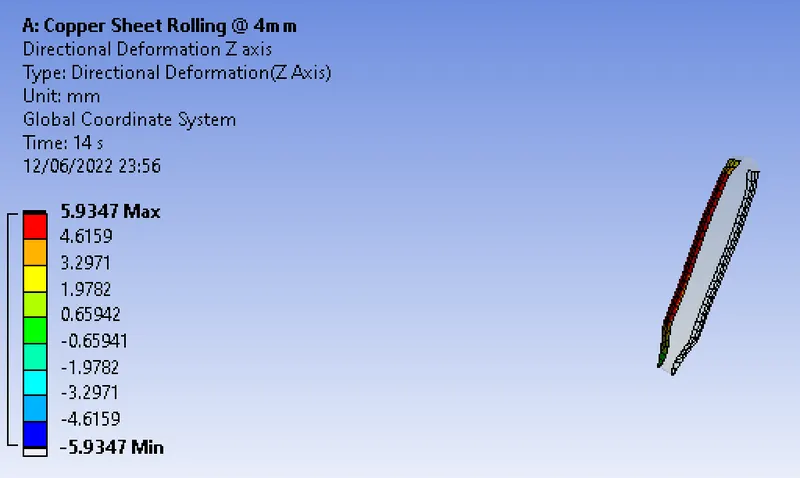
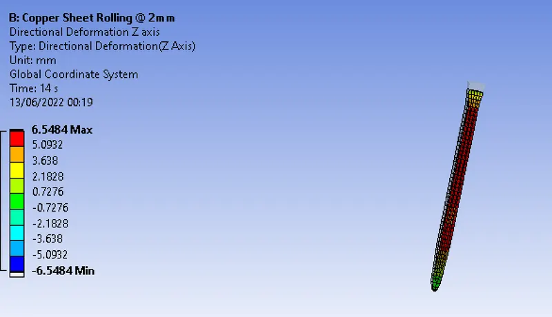
Directional Deformation in Z-axis 4mm Directional Deformation in Z-axis 2mm
Directional Deformation in the Y-axis for the workpiece
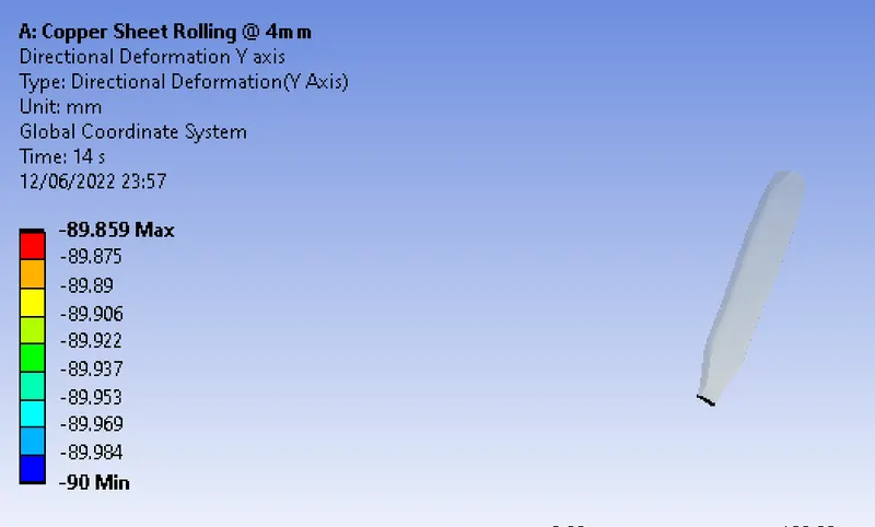
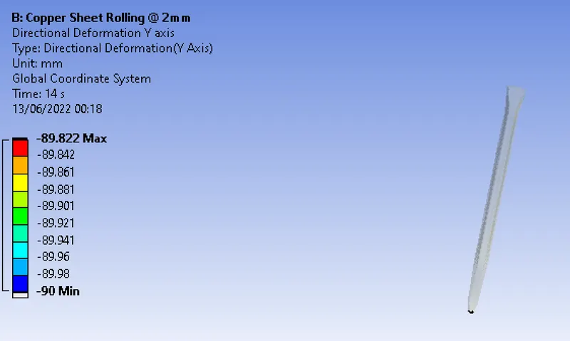
Directional Deformation in Y-axis 4mm Directional Deformation in Y-axis 2mm
Comparison Table:
|
Element Size |
Maximum |
||||
|
Total Deformation |
Equivalent stress |
Equivalent plastic strain |
Directional Deformation Z-axis |
Directional Deformation Y-axis |
|
|
4mm |
6.2313 mm |
3680.5 MPa |
1.3942 mm |
5.9347 mm |
-89.859 mm |
|
2mm |
6.2683 mm |
3205.8 MPa |
1.7931 mm |
6.5484 mm |
-89.822 mm |
Comparison:
From the above data, we can conclude that the workpiece has been displaced 90mm in both the cases with element sizes 4mm and 2mm.
To conclude the better results with respect to element size we should consider less Total deformation and Equivalent stress but Equivalent plastic strain should be higher. From the above comparison table, we can conclude with an element size of 2mm we achieved better results.