Week 4- Rolling operation
Aim: To perform a copper rolling sheet simulation using the Ansys workbench.
Objective:
Simulate the rolling operation on a workpiece made of copper. The model will be provided to you. Increase the length of the workpiece by 60mm and decrease its size on both sides by 8mm. Run the simulation for 14 steps and you can give small but random values( similar to the ones mentioned in the video) for the displacement. Ensure that the edge of the workpiece is displaced by 90mm.
Find out the
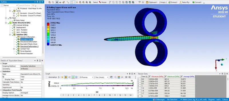
- Equivalent stress for the whole setup
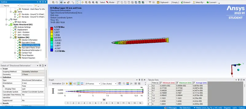
- Equivalent Plastic strain for the workpiece
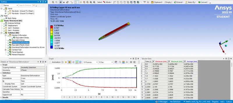
- Directional Deformation in the Z-axis for the workpiece
- Prove that the workpiece has displaced by 90mm
Theory:
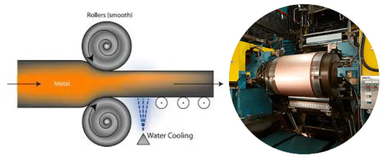
In metalworking, rolling is a metal forming process in which metal stock is passed through one or more pairs of rolls to reduce the thickness, make the thickness uniform, and /or impart a desired mechanical property. The concept is similar to the rolling of dough.
For copper cold rolling and foil rolling, several types of mill are selected according to the rolling process, thickness and materials to be produced. Our typical mill type is the UCM-Mill, which is suitable for rolling to thin gauge. The alternative X-Mill technology is another of our typical mill types for thin copper and copper alloy foil rolling. 4Hi, 6Hi, 12Hi CR mill and 20Hi ZR cluster mill are also applied by us for cold rolling of copper and copper alloys.
CAD Model:
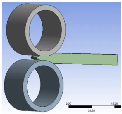
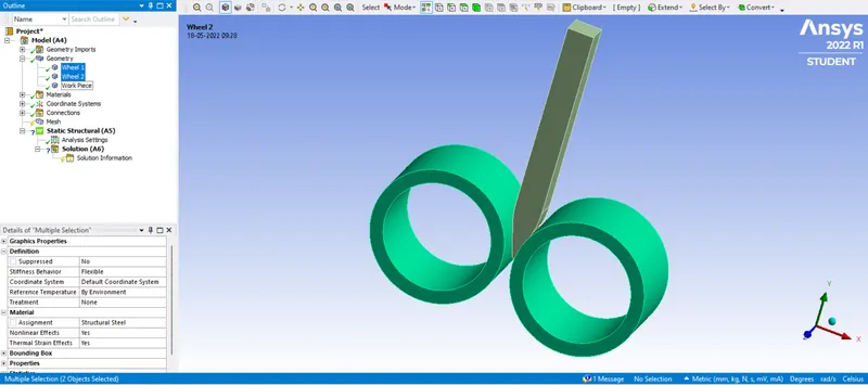
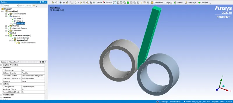
The CAD Model consists of two rollers and a workpiece. Two rollers will rotate in opposite directions and metal is fed in between the rollers thus the thickness of the metal is reduced.
Procedure:
1) To verify welds in the setup, we use the static structural tool in the analysis system toolbox to define the geometry and other input parameters for the same.
First, we open SpaceClaim to identify and rectify the errors in the geometry. In the below geometry we can see the copper rolling
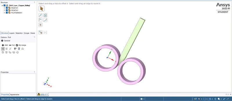
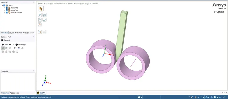
Extend the length of the rod by 60 mm and reduced the width of the rod on both sides by 8mm.
2) In the engineering data we input the material and its properties. In this case, we are using three different types of materials and their properties are shown below.
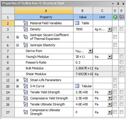
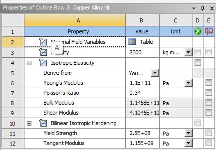
3) In the geometry of the model, the Wheels are made up of Structural Steel metal and Copper rolling is made up of Copper Alloy.
4) In connection, we have to define the contact faces of the geometry by selecting and deselecting contact or target bodies. In contacts under the connection tab, we define the type of contact as frictional contact.
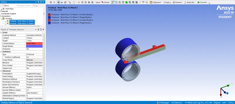
With Type as Frictional, Frictional Coefficient as 0.2, Formulation as Augmented Lagrange, Normal Stiffness as Factor, Normal Stiffness factor as 0.1 and Update Stiffness as Each Iteration.
5) Defining Joints of the geometry for rotation of the body in the desired direction
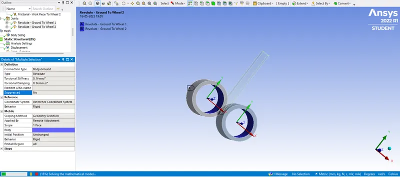
6) By opening the modelling tab, we mesh the geometry with element size as default and finer mesh size where contacts are present. Generating the mesh thereafter by right-clicking on the Mesh icon. Finer mesh is used for the workpiece which is going to get deformed wherever the workpiece comes in contact.
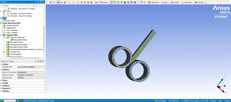
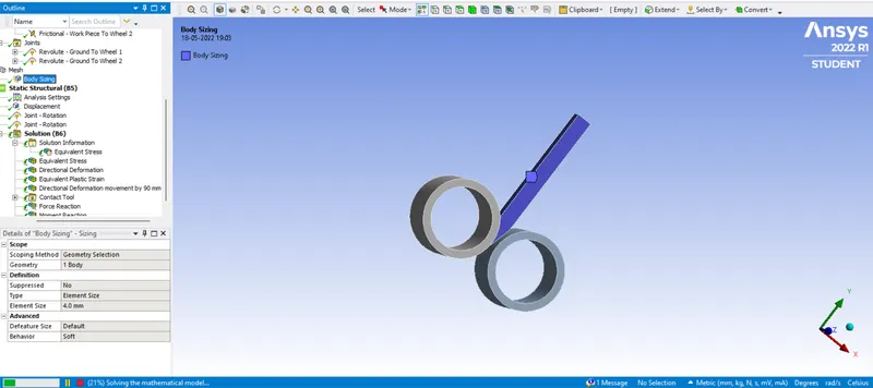
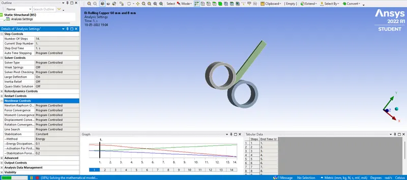
7) We open the analysis setting where stimulation is run for 14 steps for Displacement and Joint-Rotation
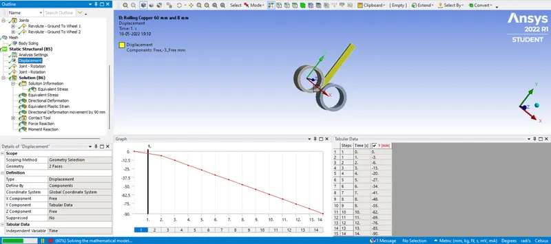
Displacement of the workpiece is done for 90 mm in negative direction of Y-axis as values given in table as 0, -3, -6, -13, -20, -27, -34, -41, -48, -55, -62, -69, -76, -83, -90.
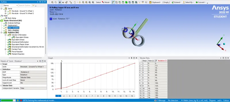
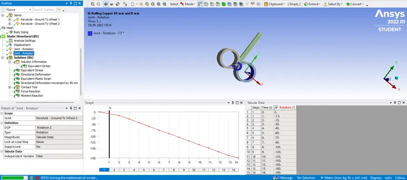
Joint-Rotation is given as shown below
7) Setting up the solution:
a) Equivalent Stress for Whole Setup:
b) Equivalent Elastic Strain for the workpiece:
c) Directional Deformation in the Z-axis for the workpiece:
d) Displacement of the workpiece by 90 mm:
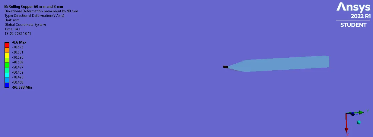
we can see that the movement from -90 mm to 0.6 mm means the workpiece has moved 90 mm.
Result:
| Material | Copper |
| Equivalent Stress in Mpa (Maximum) | 2418.2 |
| Equivalent Stress in Mpa (Minimum) | 2.537e-003 |
|
Equivalent Plastic Strain (Maximum) |
1.4738 |
| Equivalent Plastic Strain (Minimum) | 5.3048e-003 |
| Directional Deformation in Y-axis in mm (Maximum) | -0.6 |
| Directional Deformation in Y-axis in mm (Minimum) | -90 |
|
Directional Deformation in Z-axis in mm (Maximum) |
5.5758 |
| Directional Deformation in Z-axis in mm (Minimum) | -5.5758 |
The above tabular data shows the equivalent stress, equivalent Plastic Strain, Directional Deformation (Z-axis), and Directional Deformation (Y-axis) of the Copper material. Copper experiences maximum equivalent stress of 2418.2 MPa, for the whole body, Equivalent Plastic Strain for the workpiece is 1.4738, and the Maximum Directional Deformation in the Z-axis for the workpiece is mm, we have proven that the workpiece has displaced by 90 mm by assigning the displacement value randomly, up to -90 mm.
Conclusion:
from the above result, we can conclude that the equivalent stress of Copper is 2418.2 MPa and this value is appropriate as it is followed by a grid dependency test.
The workpiece has displacement, up to 90 mm is proved by adding a random value to the displacement, up to 90 mm.
The tip of the workpiece is chosen as Geometry and by the directional deformation, the workpiece is displaced by 90 mm as shown in the above figure.
Note: google drive link is provided below in a text file. Please check the link for the model.
Thank You...