Week 4- Rolling operation
Aim
a) To perform structural analysis by simulating the rolling operation on a workpiece made of copper.
b) To find out the output reults as per the given data by changing the dimensions of workpiece.
c) To prove the displacement of workpiece edge as per the requirement.
Procedure
1. Imparting the geometry
first of all, after starting the ANSYS Workbench the given rolling model of copper has been imparted in ANSYS and then the given model was opened in ANSYS Spaceclaim to modify the geometry as given below:
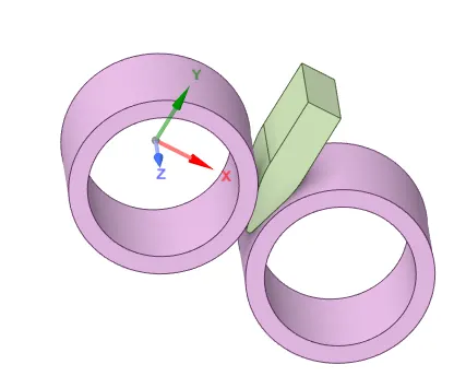
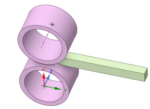
The above figure is the given geometry and using the pull option the length of workpiece has been increased by 60 mm and then the thickness of workpiece has been reduced by 8 mm on both the sides. The new edited geometry is shown as below:
2. Material Data
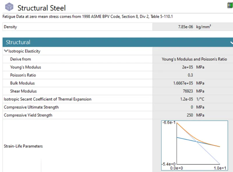
The material used for rollers were structural steel which is shown below:
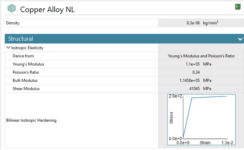
The material used for sheet was copper and the properties are given below:
3. connections
3.1 Frictional Contacts
3.1.1 Wheel 1 to Sheet
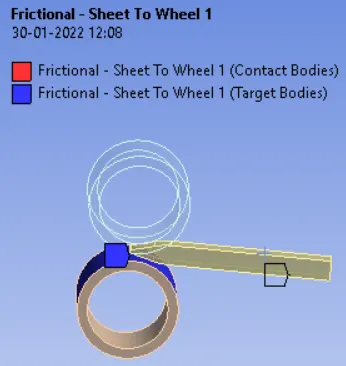
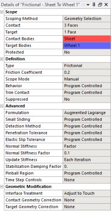
As shown above, the nature of contact was choosen as frictional between wheel 1 and sheet. Coefficient of friction was selected as 0.2 with normal stiffness factor as 0.1. The interface treatment was elected as adjust to touch.
3.1.2 Wheel 2 to sheet
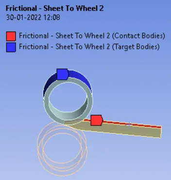
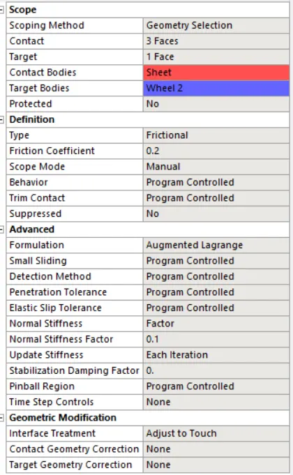
As shown abobe same settings have been applied for wheel 2 to sheet.
3.2 Cylindrical Joints
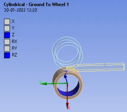
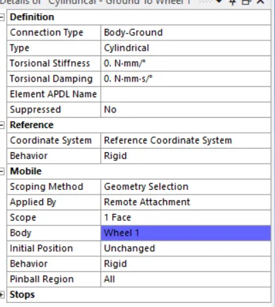
As shown above, the cylindrical joint has been defined for the selected face of wheel 1. The rotation was about Z axis.
Similarly cylindrical joint 2 has also been defined as shwn below:
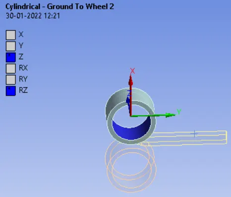
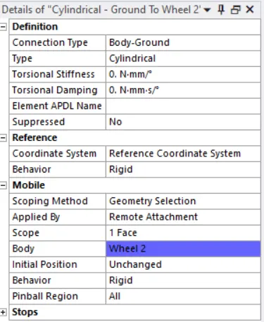
4. Analysis Settings
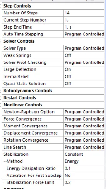
As shown below the analysis was done in 14 steps and sice the material used was copper NL and to consider this effect the normal stiffness was given in terms of constant as 0.1.
5. Load Details
5.1 Displacement
 \
\
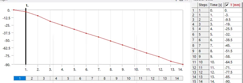
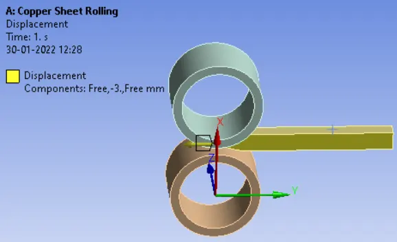
As seen in the above figure, the displacement was given to the sheet by selecting two side faces of the sheet to avoid any slipping. The 14 steps were given the displacement values as shown in the table. The total displacement was 90 mm.
5.2 Joint Rotation 1
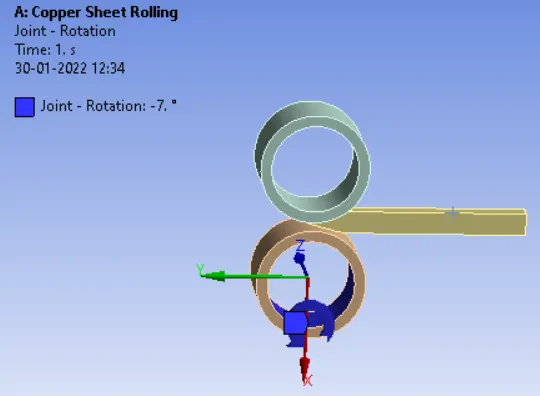
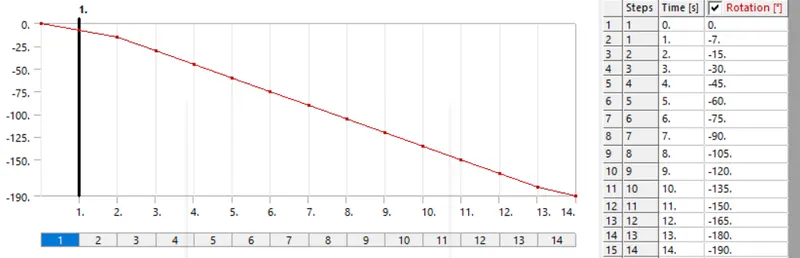
As shown in above figure, the rotation was given in 14 steps in the interval of around 15 deg. The last rotation value was 195 degree.
5.3 Joint Rotation 2
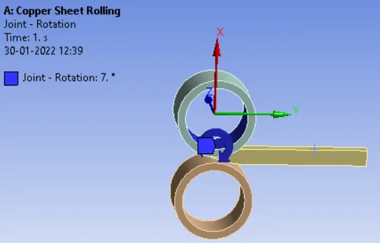
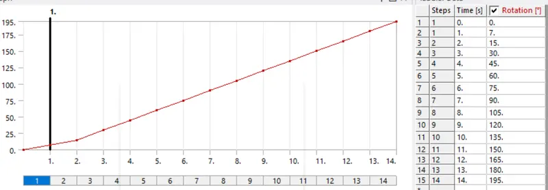
As shown above, the opposite direction rotation with respect to first rotation was given to the second cylindrical joint. The details are as below:
6. Results
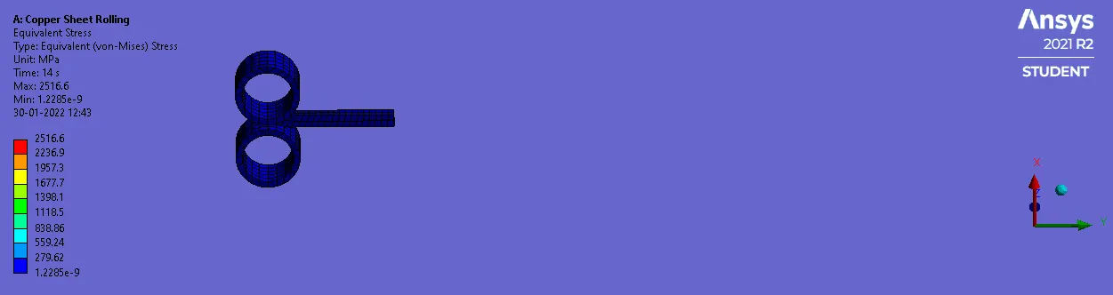
6.1 Equivalent Sress
6.2 Directional Deformation
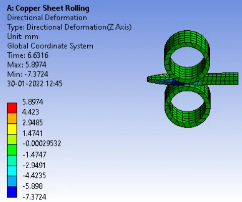
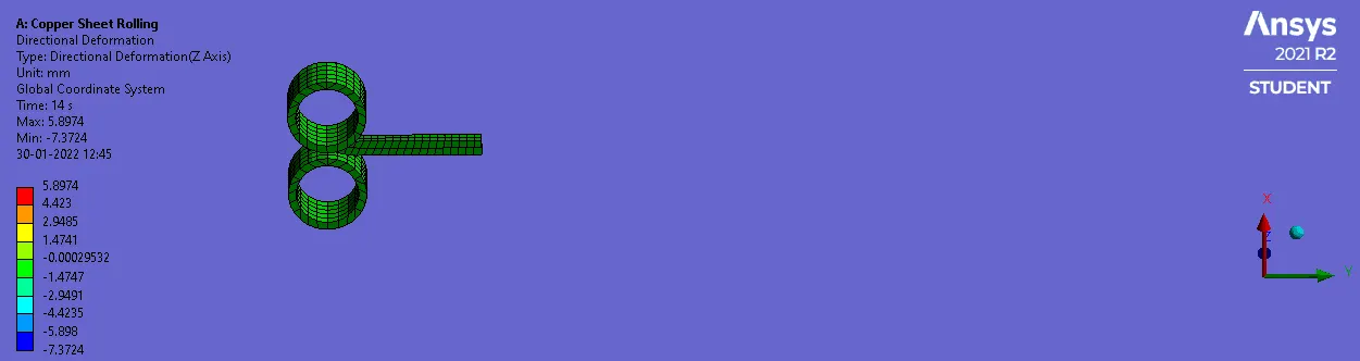
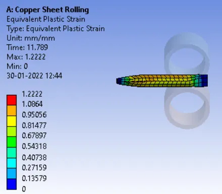
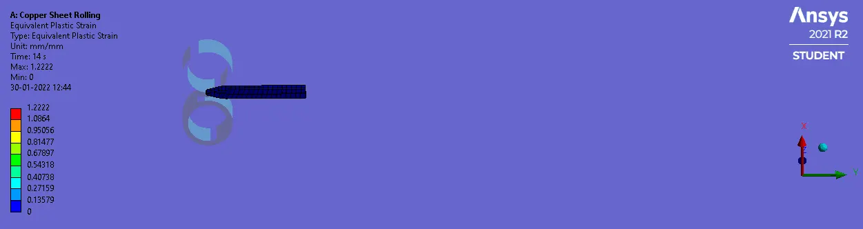
6.3 Equivalent Plastic Strain
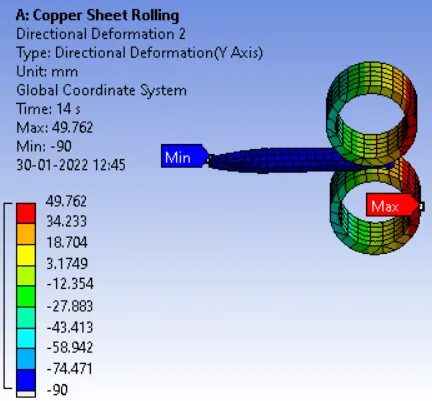
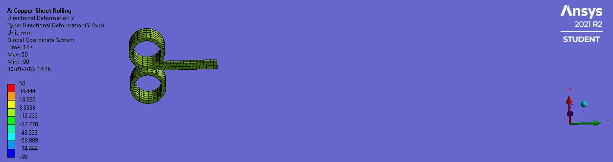
6.4 Edge Displacement
7. conclusions
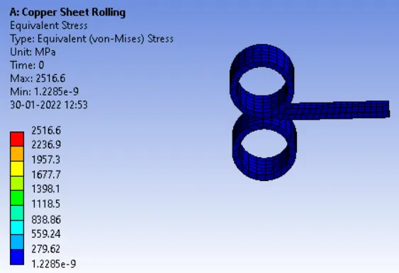
a) As shown in the results, max stress value in the given rolling setup was 2516.6 MPa.
b) Max directiona deformation of sheet along the side faces was 5.8974 mm.
c) Maximum value of equivalent plastic strain was 1.222 mm/mm.
d) As it can be seen from results, edge has been displaced by 90 mm.