Week 4: Project - Steady state simulation of flow over a throttle body
STEADY FLOW OVER A THROTTLE BODY
INTRODUCTION: A throttle is a mechanical device that is used to regulate the flow.Throttle is cylinder in shape and is controlled by mechanism such as throttle lever ,acclerator etc.It is used in various machine, engine and other devices.
Case setup :Pressure based steady state solver is used. In this case air is used which is compressible. There are four boundary condition in this case. Inlet wall is set as inflow boundary, outlet wall is set as outflow boundary, elbow wall is set as wall boundary(law of wall),throttle is set as wall boundary which is of rotating type. Other specification are given below
1).Pressure at inlet is set to 100000pa
2).Pressure at outlet is set to 100001pa
3).Temperature is specified as 300k
4).Species concentration(oxygen 23%,nitrogen77%)
5).Start time is set to 0 cycle
6).End time is set to 15000cycle
7).initial time step is 0
8).minimum time step is 1e-9
9).maximum time step is 1
10).maximum CFL criteria is set to 0.5
11).SOR solver type is used and preconditioner is set to none
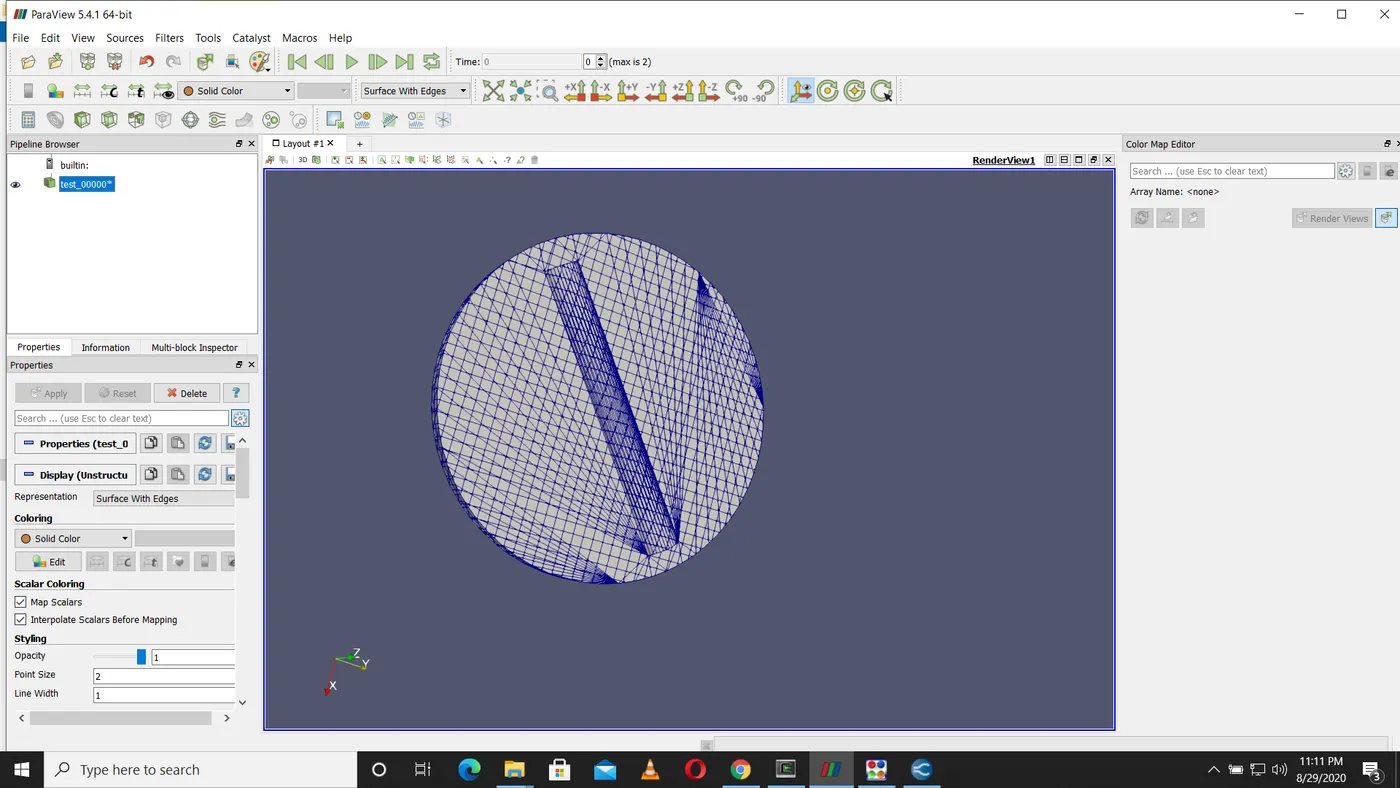
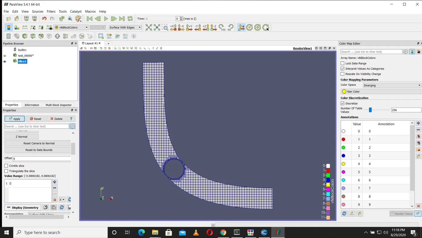
12).Embedded mesh with scale factor 2 is used in throttle body
13).RANS K-epsilon turbulence modelling is used
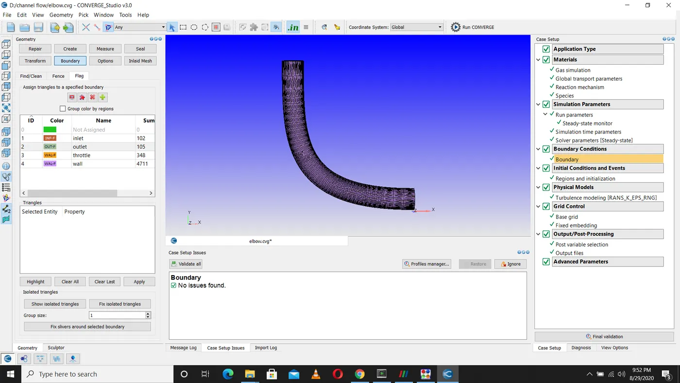
The plots and contour are given below
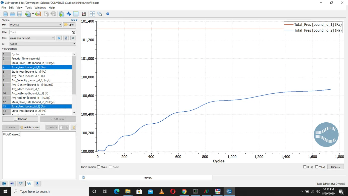
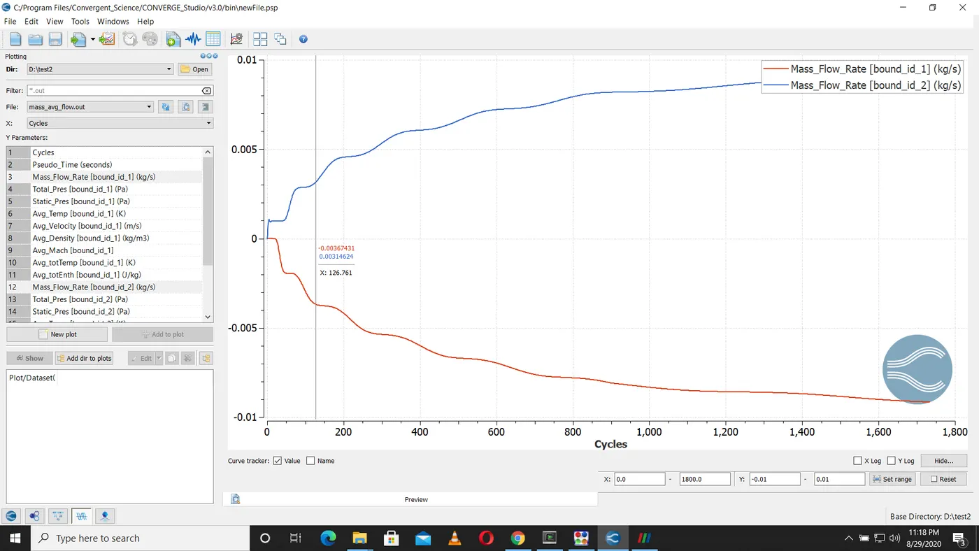
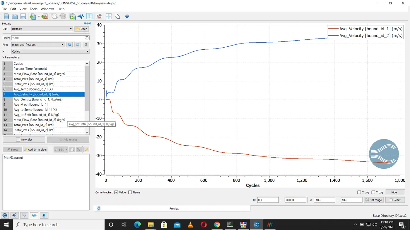
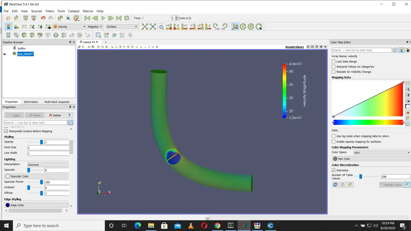
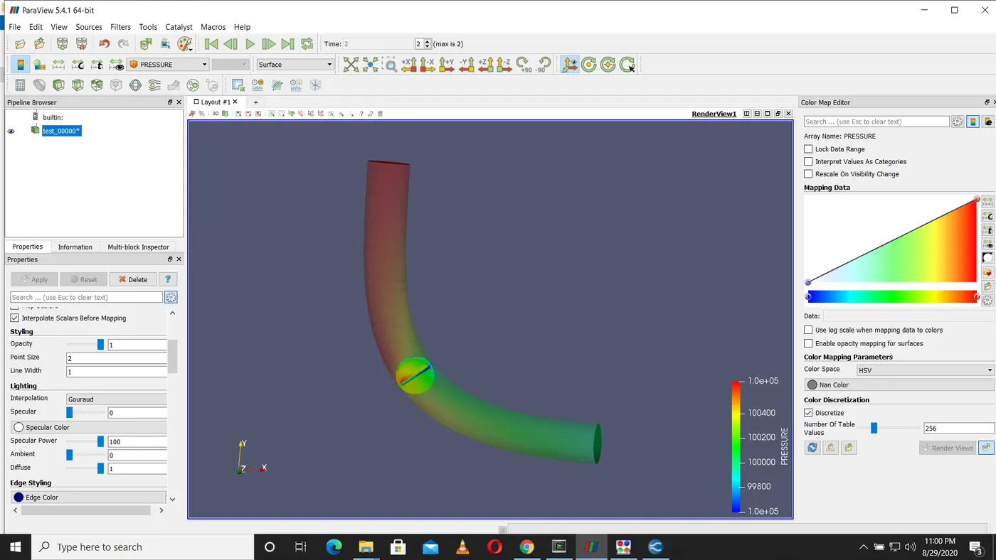
From the above plot we can see that velocity and pressure changes when the flow encounter throttle.When the flow encounter the throttle the velocity decreases and the pressure increases at the throttle body.It can also be noticed that there is some leakage of fluid as indicated by the red colour as shown in the above figure.