Week 4 Project - Simple Crank Mechanism
1)
step 1:(process repeated like previous assignments)
- select motion view
- set up the gravity component to the negative y-direction
- change the units from mm to M
step 2:
- add the points with respective coordinates
- add bodies
- add graphics giving proper origin, parent bodies, and dimensions od dia 2m
- assigning the properties for bodies by selecting "get properties from associated graphics to get meaning full mass and inertia
- add joints at point0 and 1
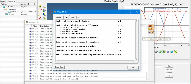
- to have a check on the model for redundancy
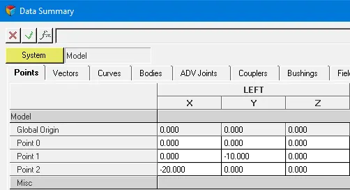
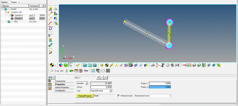
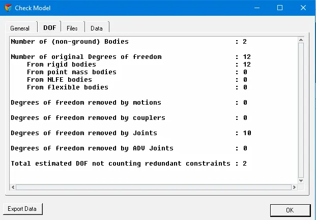
step 3:(solution to remove redundancy)
- inline joint is used which has DOF=2, which makes the DOF=0 of for system and removes the redundancy
for revolute joint:
DOF of one rigid body=6
DOF of two rigid body=12 ...(1)
DOF removed by one revolute joint=5
DOF removed by two revolute joint=10 ...(2)
DOF of the system => (1)-(2) = 12-10 = 2
for inline joint:
DOF of one rigid body=6
DOF of two rigid body=12 ...(1)
DOF removed by one revolute joint=5
DOF removed by two revolute joint=10
DOF removed by inline joint=2
total DOf by joints= 10+2 = 12...(2)
DOF of the system => (1)-(2) = 12-12 = 0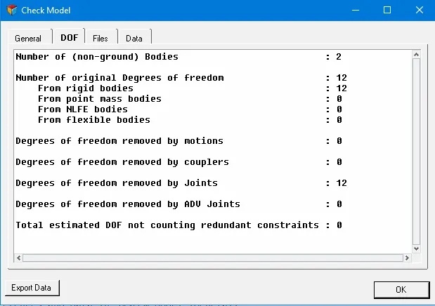
2)
step4:
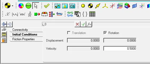
- set up initial conditions for joint0
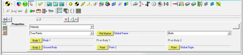
- add outputs
- run the simulations for 15sec
- plotting the graph for velocity
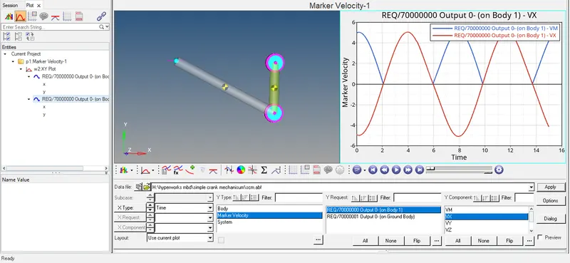
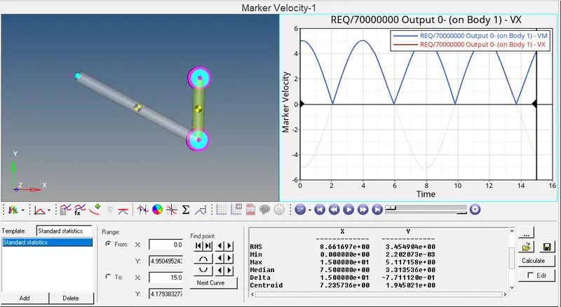
- max velocity = 5.117m/sec^2
- the DOF of the system remains the same.
3)
step5:
- suppressing the initial angular velocity
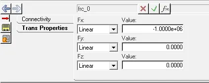
- adding force in force tap option
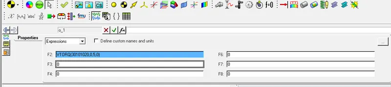
- reacting output1 and assigning torque equation.
- plotting the results

expression = `VTORQ({j_0.joint_i.idstring},{0},{5},{0})`
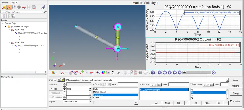
from the plot, we get the clarity that there is no reaction or change in the system.
4)
step6:
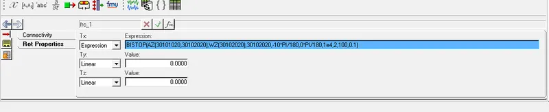
- adding force1 from force tap and assigning it with the bishop function, for the force
expression = `BISTOP(AZ({j_0.joint_i.idstring},{j_0.joint_j.idstring}),WZ({j_0.joint_j.idstring}),{j_0.joint_j.idstring},-10*PI/180,0*PI/180,1e4,2,100,0.1)` - modifying the output1 with the following expression
expression = `VTORQ({frc_1.idstring},{0},{5},{0})` - the required graph is plotted


results: the required simulations for simple crank mechanism are done in motion view and motion solve