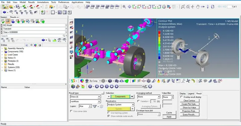
Week 12 - Flex Bodies
Objective:
- Determine the Maximum and Minimum Stress and Strain Values in the Flexible Lower Control Arm.
- Run a Static Ride Analysis. Run a sensitivity study on the following parameters to conclude which parameter/ combinations of the parameter have a maximum effect on the stress/strain of the lower control arm.
- Parameters to be considered:
- Vehicle CG
- Axle Ratio
- Vehicle Weight
- Front Brake Ratio
- Wheelbase
- Spring Rate
- Preload
- Spring Hard-Points
Introduction: While designing a suspension system for a vehicle, one should often not ignore the loads that suspension linkages take up during jounce or rebound. Finite Element Analysis wouldn't be sufficient to analyze displacement, stress, and strain acting on the linkages since it does not take into account the collective behavior of the suspension system. Moreover, Finite Element models have a very high number of degrees of freedom which is difficult for MBD solvers to handle. In such a case Flex-Body simulations come into play that allows the engineer to test the strength of linkages without isolating them from the geometry. A flex body is a modal representation of the Finite Element model, an approximation of a deformable structure for CAE analysis. It is based on the concept of modal superposition and is therefore very efficient for solvers that need to model structures as non-rigid. The MBD solver calculates the coefficients for the various deflection modes calculated in the Component Mode Synthesis method which when added together produces the deformed shape. Flexbodies connect to the MBD system through the interface nodes.
Component Mode Synthesis: There are three CMS methods available in OptiStruct that would reduce the Finite Element Model to a set of orthogonal mode shapes:
- Craig-Bampton - To be used when most of the degrees of freedom of the interface node are constrained by the MBD model.
- Craig-Chang - When most of the degrees of freedom of the interface nodes are not constrained in many degrees of freedom by the MBD model.
- Craig-Bampton Geometric -Stiffness - best when analyzing slender structures that have considerable influence on geometric stiffening effects, especially during spinning.
A common requirement of the CMS method is that the exterior grid points must be able to move independently of the interior nodes of the flexible body. A common case that caused CMS failures is when the center point of a rigid spider which is defined as a flexible body interface node is dependent on the displacement of the outer nodes. To avoid this the configuration of the RBE3 element must be changed to the RBE2 element. To understand what this means one needs to first understand what RBE2/3 spiders are.
RBE is a rigid body element. RBE2 elements rigidly connect an independent FEA node to one or more dependent nodes. Most often for MBD flexible bodies, the RBE2 elements are "rigid spiders" that have the independent node at the center of a hole and the dependent nodes along with the circumference modeling bolts or other connection hardware. The independent node of the rigid spider becomes an interface node of the flexible body that allows the body to connect to other elements like joints or forces in the MBD model. RBE3 - On the other hand, for the RBE3 element, the dependent node is in the center and the independent nodes are along the circumference.
Model-Building Process:
The model building process is involved in two stages: Flexbody Generation and Replacement of flex-body with the rigid lower control arm.
Stage 1:
- MotionView GUI is opened. Then under 'FlexTools' Flex Prep is selected. This opens a dialogue box where the flex-body will be created. The Finite Element model of the lower-control arm is imported into Hyperworks.
- A suitable file name is chosen to save it as an h3d file. Craig-Bampton is selected as the component mode synthesis method since most of the degrees of freedom of the interface node are constrained by the MBD model.
- The interface nodes are specified as 4887+4888+4890. The node IDs of the RBE2/ RBE3 central nodes will be the interface nodes. The node IDs are read from HyperMesh while creating the flex-body.
- The next step is to choose the highest mode number which specifies the cut-off value and type. The default value of 15 is selected as the highest mode # As the highest mode number increases the accuracy of the solution increases till convergence is reached. However, with an increase in the number of the highest mode number, the computational time and power also increase significantly. So, there is always this trade-off.
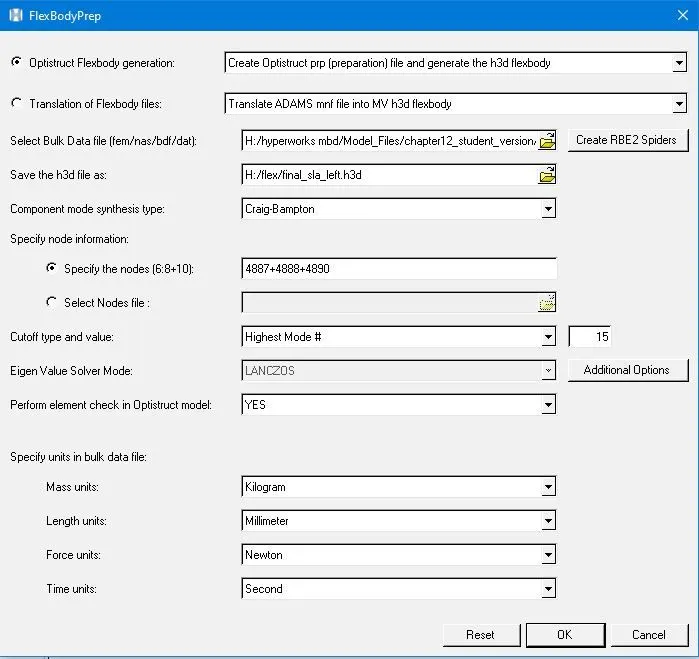
- The solver mode is chosen as Lanczos which is the default algorithm in OptiStruct. Under the additional options Perform Stress Recovery and Perform Strain Recovery needs to be checked'.
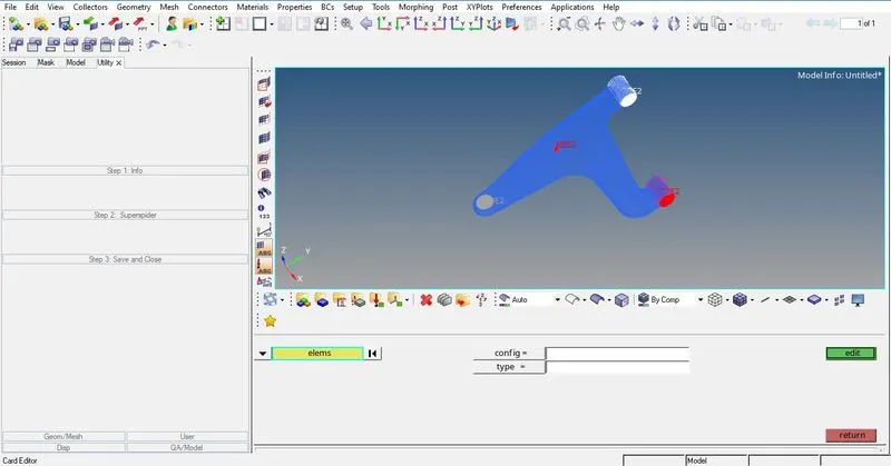
- To avoid CMS failures the RBE3 spiders need to be converted to RBE 2. Clicking on Create RBE2 spider' launches HyperMesh. Once Hypermesh is launched, OptiStruct needs to be selected under User-Profiles. The lower control arm appears on the screen
- RBE2 spider needs to be created on the outer part of the lower control arm which would attach to the knuckle. This is done by clicking on utility-user-Stop 2 Super spider. This prompts the user to select an element on the hole following which an RBE2 spider is created. There are 3 more RBE spiders located on the LCA, One which would attach to the spring and the rest two would attach to tho bushing.
- The spider which would attach to the spring is an RBE2 type. By going to card edit elements and then selecting one of the RBE elements it is found that it's an RBE3 spider. To convert this to RBE2 the following steps need to be followed: Select ID-ConfigEdit-Select the RBE3 elements on the LCA-new config-rigid link and then click on the switch. To verify that the conversion took place we go back to the card edit option. The file is then saved in fem format which then re-directs to MotionView.
Stage II:
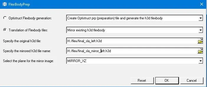
- Since only the left LCA flex-body was created we need to create the right LCA too. This can be done easily using Translation of FlexBody Files and then selecting Mirror's existing h3d body option. The original h3d file is imported and its corresponding mirrored h3d is specified.
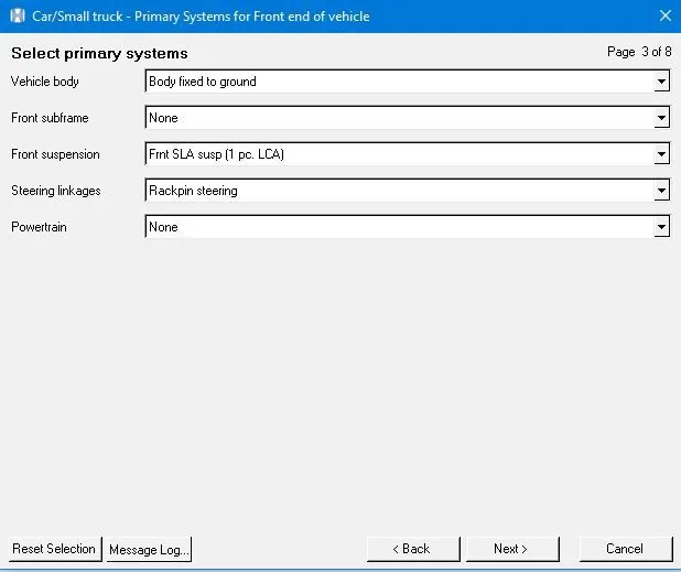
- Using the assembly wizard the front end of the vehicle is created. Front SLA susp(1 pc LCA) needs to be selected. Rest all options are set to default. Next, under analysis, the task wizard is selected to create a test rig for the vehicle model which would be used to run Static Ride Analysis.
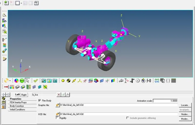
- By default the LCA of the vehicle is rigid which needs to be replaced with a tho generated flex-body. To do this, the Lwr Control arm is selected under Front SLA susp from the Project column. Symmetric properties need to be unchecked and Flex Body CMS is checked. The h3d file for both left and right LCA is then imported
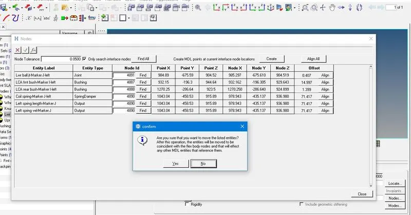
- After importing the LCA flex-body it is observed that they are misaligned from the knuckle and bushing. The misalignment is corrected by clicking on nodes Find All-Align All. One also needs to verify that the rigid body modes are unchecked. This step completes the model-building process.
stage 3:
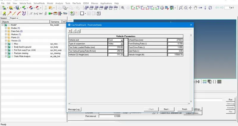
- vehicle parameters for the first trial and its respective results
displacement: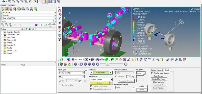
2. strain: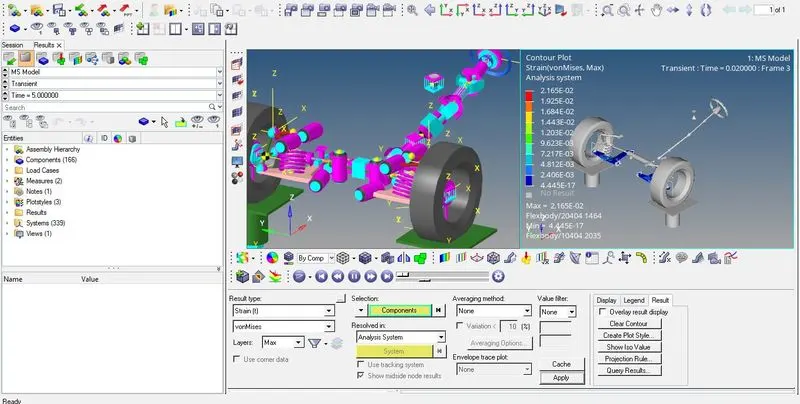
3. stress: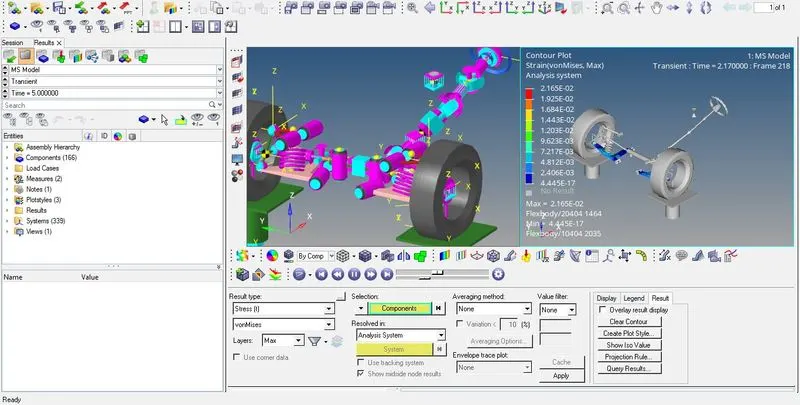
- vehicle parameters for the second trial and its respective results
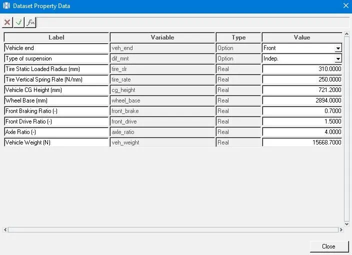
1.displacement: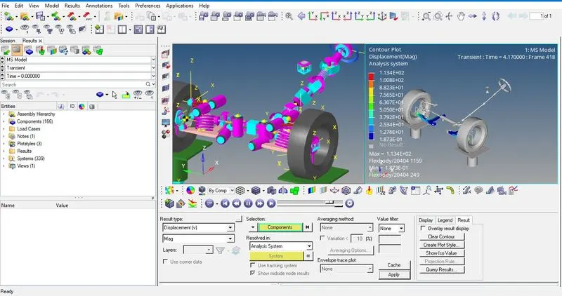
2. strain: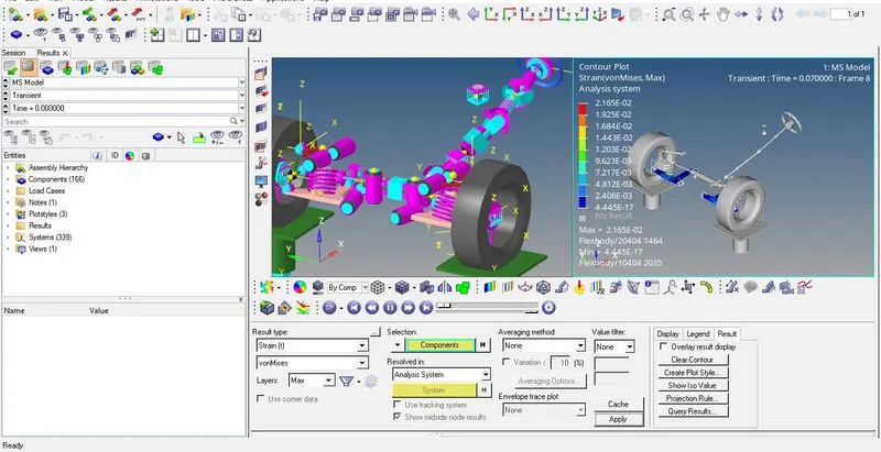
3. stress: