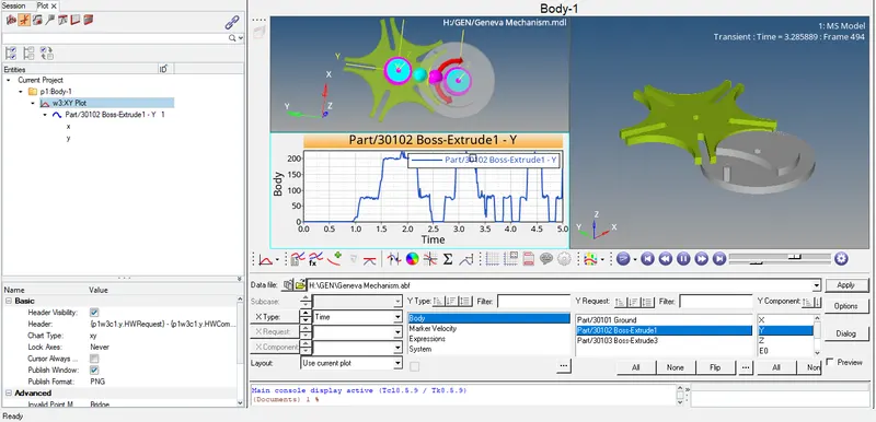
Mid Project - 2
GENEVA MECHANISM: A Geneva Mechanism is a commonly used mechanism for producing an intermittent rotary motion from a uniform input speed. The driven member, or star wheel, contains evenly spaced slots into which the roller of the driving crank slides. The number of slots determines the ratio between the driven shaft's dwell (stationary) and motion periods. The mechanism requires a minimum of three slots to function and additional slots can be added. If the driven wheel has n slots, it advances by 360°/n per full rotation of the drive wheel.
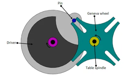
As the Drive wheel turns it enters the slots of the driven, or star, wheel and the mechanism enters its motion period. As the pin leaves the slot the driven wheel has been indexed and it continues to stay stationary until the pin rotates back around. Because the driven wheel is always under full control of the driver, the impact is a problem. It can be reduced by designing the pin in such a way that the pin picks up the driven member as slowly as possible.
Applications of Geneva Mechanism.
- Both Geneva mechanisms can be used for light and heavy-duty applications. Generally, they are used in assembly machines.
- The Geneva mechanism is a timing device. It is used in many counting instruments and in other applications where an intermittent rotary motion is required. The Geneva mechanism was originally invented by a watchmaker.
- The watchmaker only put a limited number of slots in one of the rotating disks so that the system could only go through so many rotations. This prevented the spring on the watch from being wound too tight, thus giving the mechanism its other name, the Geneva Stop. The Geneva Stop was incorporated into many of the first film projectors used in theaters.
- Another area where the Geneva Mechanism has been explored is the automotive industry where the internal combustion engine would revolve around the mechanism. The pins and slots of the machine form the combustion chambers which are utilized to drive the Geneva wheels to convert linear motion into rotary motion which can power automobiles or even be used in small engine applications.
STEPS:
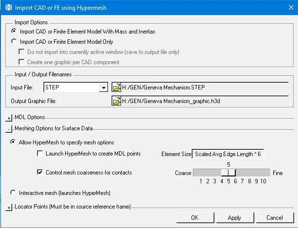
- the cad model of the internal geneva mechanism is first imported into motion view as a step file using the "import cad or fe using hypermesh"
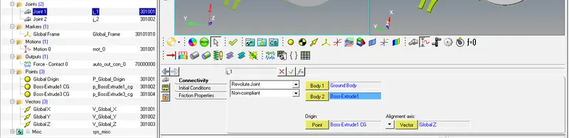
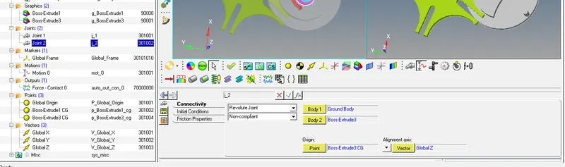
- With the model meshed, joints and contacts need to be specified. 2 revolute joints were added at the Driver CG and GENEVA Wheel CG. An Impact Contact Model is used to establish 3-D contacts between the geneva wheel and the driver.
The Normal Force values used in defining the impact Model are:
Stiffness-1000 N/mm
Exponent-2.1
Damping-0.1
Penetration Depth-0.1
Static and Dynamic Friction force was established between the two parts with the following values:
MU Static-0.2
MU Dynamic-0.1
Stiction Transition Velocity-1mm/s
Friction Transition Velocity- 1.5 mm/s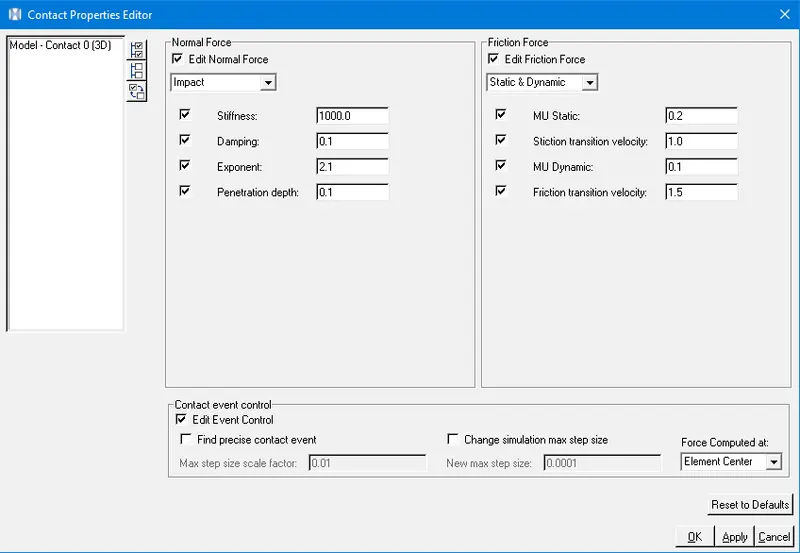
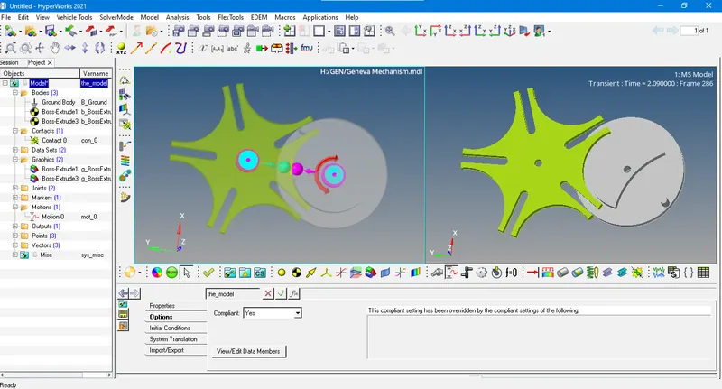
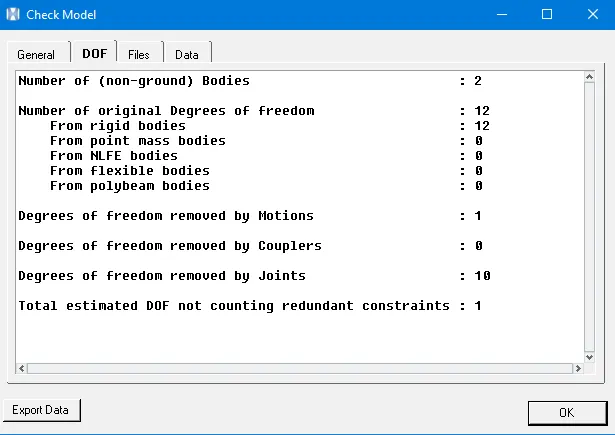
- A motion is added on the Driver Wheel Joint, allowing the Driver Wheel to rotate. The expression used to define the motion was '10* TIME. An initial angular velocity of 10 rad/s is also provided along the Z-axis.

- Finally two outputs which would measure the torque and angular velocity at the driver and geneva wheel are added.