Week 4 Project - Simple Crank Mechanism
Aim :-
To Create a simple mechanism with help of inputs given and gravity in Y axis.
CREATION OF BODY
Step 1 :- Start the Hyperworks and change the list to motion View
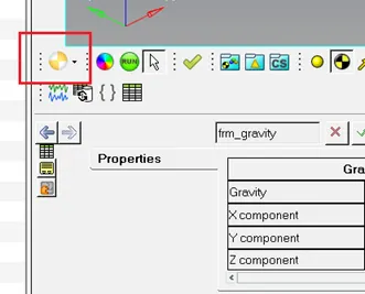
Step 2 :- Create a Body_1 & Body_2 by selecting the option shown in image below
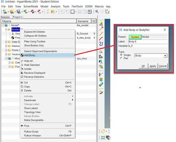
Step 3:- Change the properties for Body_1 & Body_2 for inertia and mass as shown in image below

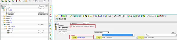
Step 4:- Change the CM properties for Body_1 & Body_2, click the option use center of mass co-ordinate system and the change the point to Global body as shown in image below
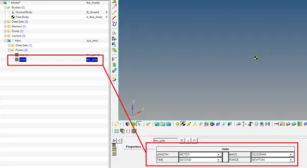
Step 5 :- Change the units as shown in image below
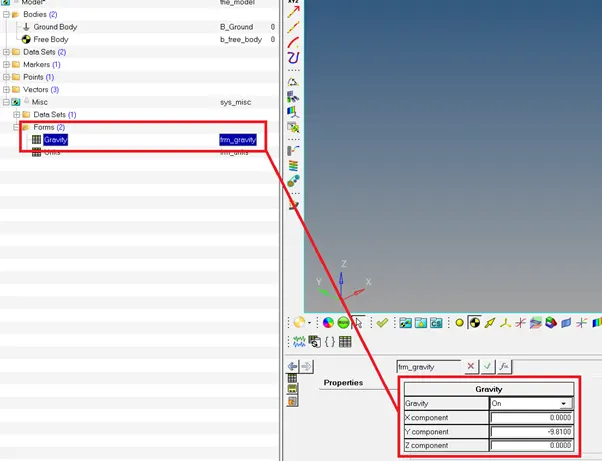
Step 6 :- Change the gravity value for Y-direction as shown in image below
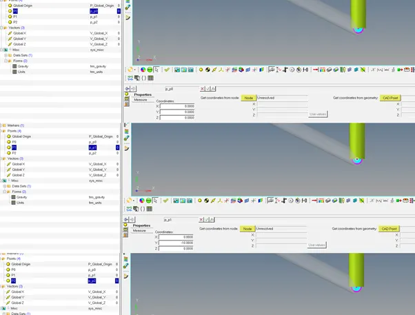
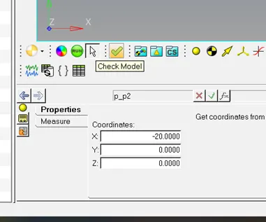
Step 7 : Create a Points P0 with coordinates (0,0,0) , P1 with coordinates (0,-10,0) and P2(-20,-0,0) as shown in image below
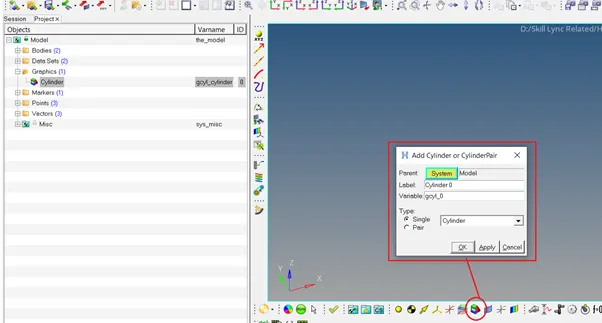
CREATION OF CYLINDERS
Step 1 :- Open graphic and create Rod_1 & Rod_2 as shown in image below
Step 2 :- In Rod_1 properties as shown in image below, select Body as Body_1 , starting Point P0 and for direction P1
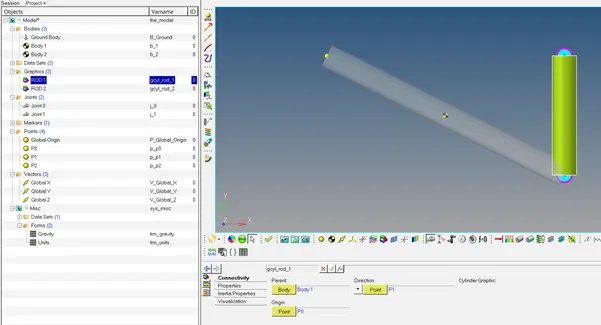
Step 3 :- In Rod_2 properties as shown in image below, select Body as Body_2 , starting Point P1 and for direction P2
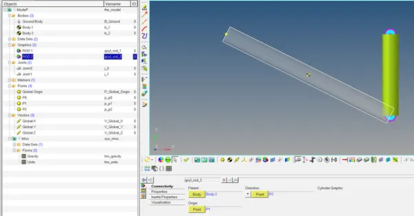
Step 4 :- Go to Body_1 & Body_2 properties as shown in image below and select the option Get properties from associated graphics
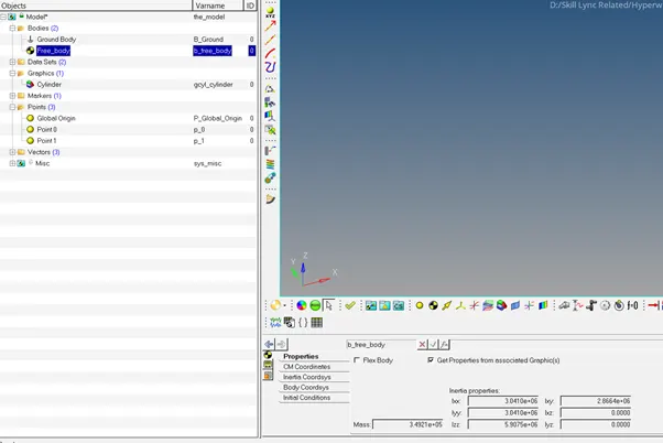
CREATION OF JOINTS
Step 1 :- Open Joint and create Joint_0 & Joint_1 as shown in image below
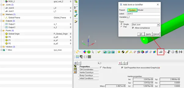
Step 2 :- In Joint_0, Connectivity option select Revolute Joint and Body 1 as Body_1 and Body 2 as Ground Body and origin as Point P0 and section Vector option and select Global Z as shown in image below.
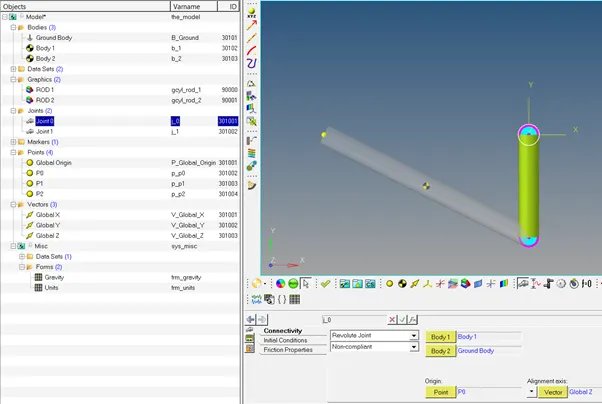
Step 3 :- In Joint_1, Connectivity option select Revolute Joint and Body 1 as Body 2 and Body 2 as Body 1 and origin as Point P1 and section Vector option and select Global Z as shown in image below.
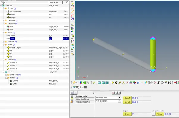
QUESTION 1
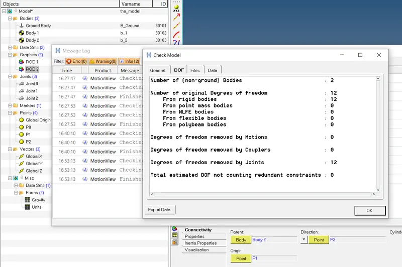
Step 1 :- Go to option check model as shown in image below
Step 2 :- A pop table will appear , select option DOF and we can see the No. of DOF without considering redundant constraints is 2.
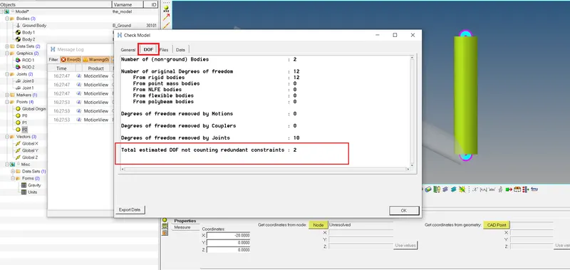
Calculation
Revolute Joint removes 5 DOF = 5 * 2 = -10
Rigid Body have 6 DOF = 6*2 =12
Therefore Total DOF = 12-10 = 2
Step 3 :- In order to solve the redundancy issue add a Inline Joint Joint at P2 as shown in image below
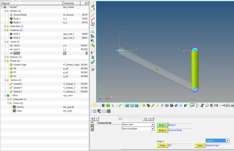
Calculation
Revolute Joint removes 5 DOF = 5 * 2 = -10
Rigid Body 6 DOF = 6*2 =12
Inline joint removes 2 DOF = -2
Therefore Total DOF = 12-10 -2 = 0
Step 4 :- Now check the Model the Total DOF will be zero as shown in image below.
QUESTION 2
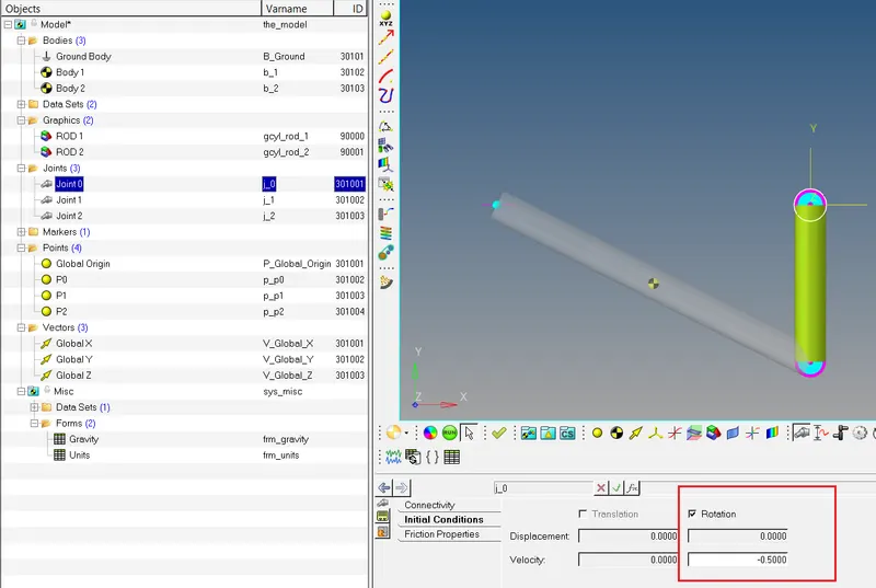
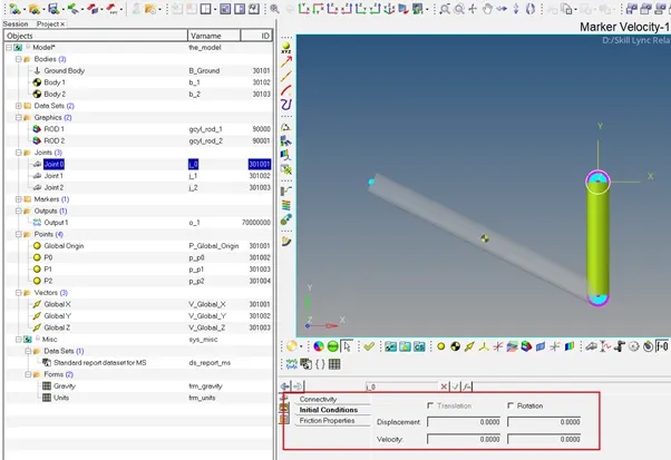
Step 1 :- From the input Initial angular velocity is 0.5 rad/sec in clockwise direction for the Joint 0 is given as shown in image below.
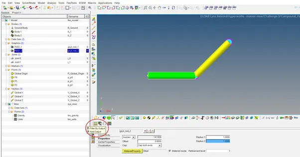
Step 2 :- Open Output and create Output 1 as shown in image below
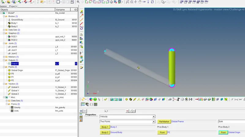
Step 3 :- In Output 1, select Velocity option and for Body 1 as Body 1 and Body 2 as Ground body Point as P2 and another point default Global origin as shown in picture below
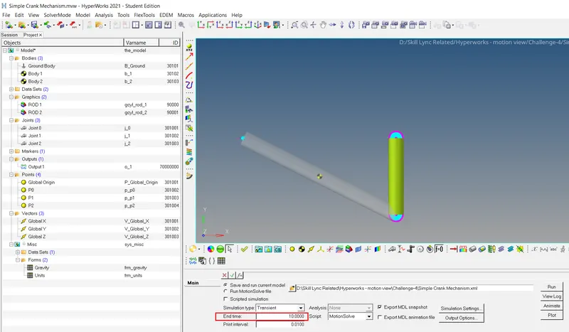
Step 5 :- Select the Run panel and change the simulation time to 10 sec as shown in picture below and click the option Run
Step 6 :- Select the option Plot (just below the Run option) and select the file simple crank mechanism.abf and select the options marker Velocity -> Body 2 to Ground body -> VM direction as shown in picture below
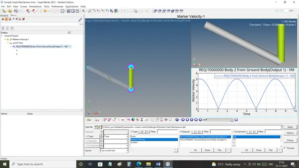
Step 7 : - The graph plotted is shown in the picture below
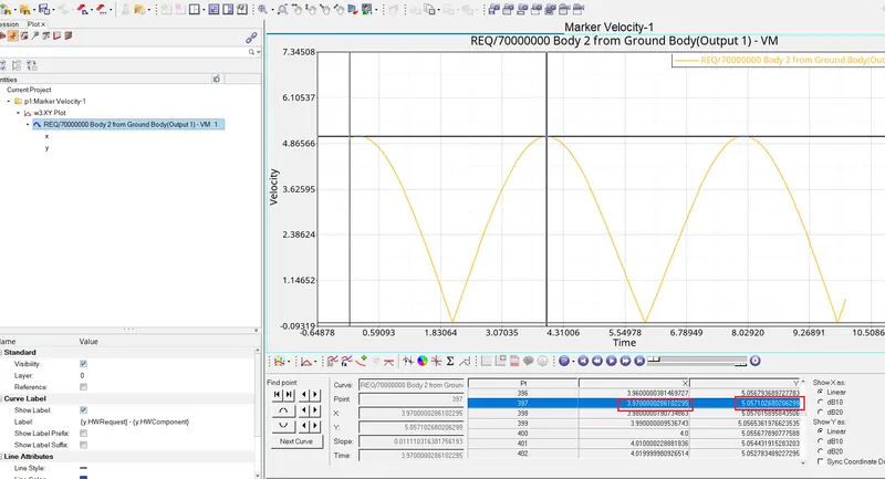
From the Plot it is clear that Maximum Velocity is 5.057 m/sec at Time 3.97 sec
And the DOF still remains zero because we apply rotation on joint 1 and there will be no change in the DOF.
QUESTION 3
Step 1 :- Remove the Initial velocity in Joint 1 as shown in image below
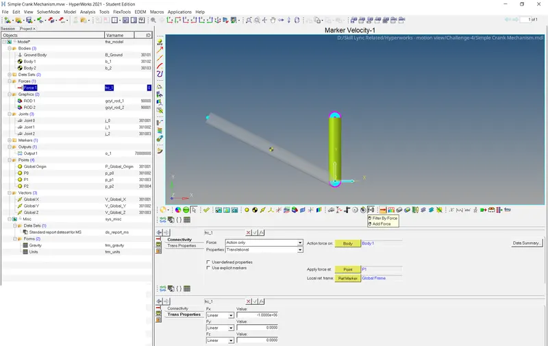
Step 2 :- Create a Force applied on P1 as shown in image below in Newton’s in negative direction
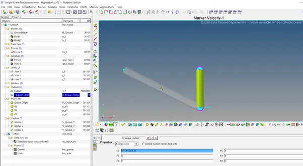
Step 3 :- Create a Output for Torque motion by selecting expressions in that select VTORQUE as shown in image below
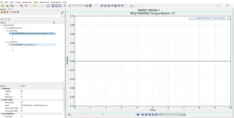
Step 4 :- From the plot graph shows a straight line as shown below becuase there is no Torque reacted on P0
QUESTION 4
Step 1 :- Create a Force using Bistop Function applied on P0 as shown in image below
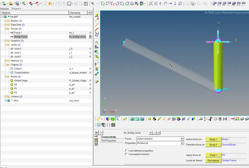
Step 2 :- Go to Rotational properties in Y direction select the Expressions and give BISTOP function as shown in image Below
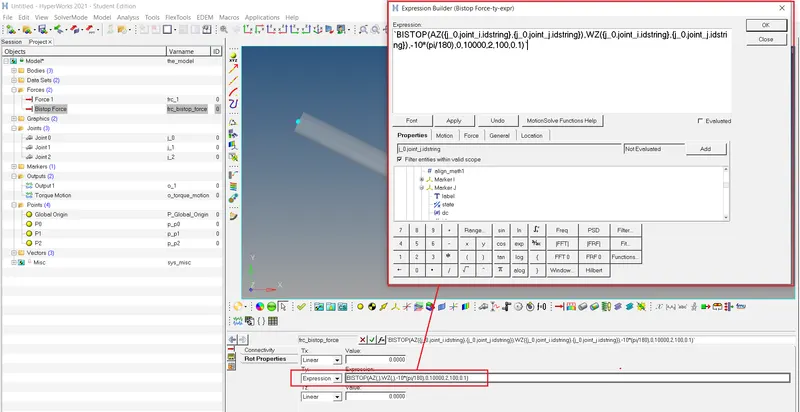
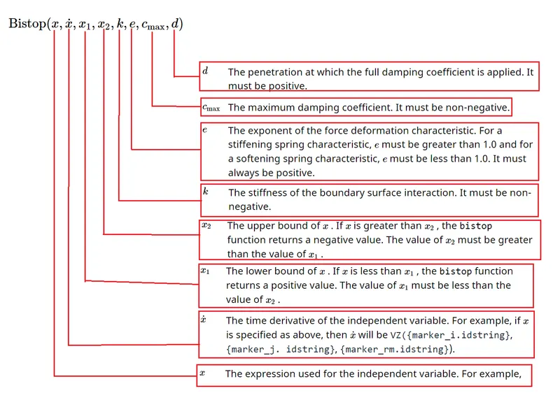
BISTOP Expression created in Y direction, for this we have 8 input shown in image below
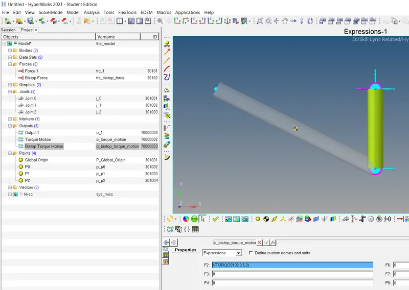
Step 3 :- Create a Output for Torque motion by selecting expressions in that select VTORQUE as shown in image below
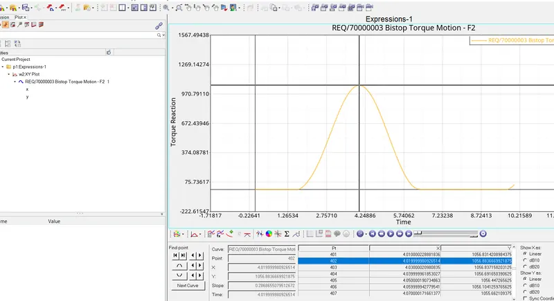
Step 4 :- The graph plotted for Reaction torque with respect to time shown in the picture below
Models and plot files are attached