MBD Simulation on a Piston Assembly
Aim: - To model and assemble the Piston parts and to do motion analysis for 3 cases.
Introduction on Piston Assembly:-
Piston assembly is one of the major component in Engine assembly. It consists of 5 parts
- Piston Head
- Wrist pin
- Connecting Rod
- Crank
Piston Head:-
This component is located in Engine cylinder connected to connecting rod, having a linear displacement inside the cylinder by the force transmitted from connecting rod.
The up and down movement of head compress the air fuel mixture in the vacuum and energy transmitted to other parts.
The piston is subjected to pressures on its head in excess of 1,000 psi.The piston head is subjected to temperatures well above 600F.
Wrist Pin:-
It holds the connecting rod and piston head.
Connecting Rod:-
Connecting rods connect the piston head to the crankshaft. They must be strong enough to transmit the thrust of the piston to the crankshaft and to withstand the internal forces of the directional changes of the pistons. The connecting rods are in the form of an I-beam. This design gives the highest overall strength and lowest weight. They are made of forgedsteel but may also be made of aluminum in smaller engines.
The upper end of the connecting rod is connected to the piston by the piston pin. The piston pin is locked in the pin bosses, or it floats in both piston and connecting rod. The upper hole of the connecting rod has a solid bearing (bushing) of bronze or similar material. As the lower end of the connecting rod revolves with the crankshaft, the upper end is forced to turn back and forth on the piston pin. Although the movement is slight, the bushing is necessary because the temperatures and pressures are high. If the piston pin is semifloating, a bushing is not needed.
Crank:-
As the piston head collectively might be regarded as the heart of the engine, so the CRANKSHAFT may be considered its backbone. The crankshaft is the part of the engine that transforms the reciprocating motion of the piston to rotary motion. It transmits power through the flywheel, the clutch, the transmission, and the differential to drive your vehicle.
Crankshafts are made from forged or cast steel. Forged steel is the stronger of the two and is used in commercial and military engines. The cast unit is primarily used in light- and regular-duty gasoline engines. After the rough forging or casting is produced, it becomes a finished product by going through the following steps:
The crankshaft is supported in the crankcase and rotates in the main bearings. The connecting rods are supported on the crankshaft by the rod bearings. Crankshaft bearings are made as precision inserts that consist of a hard shell of steel or bronze with a thin lining of antifrictional metal or bearing alloy. Bearings must be able to support the crankshaft rotation and deliver power stroke thrust under the most adverse conditions.
Model Geometry Construction:-
Piston Head
- Open solid works and set metric system to MMGS.
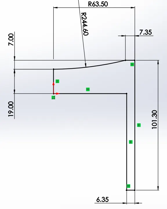
- Select front plane and sketch the below profile shown in image and use extrude revolve using that profile.
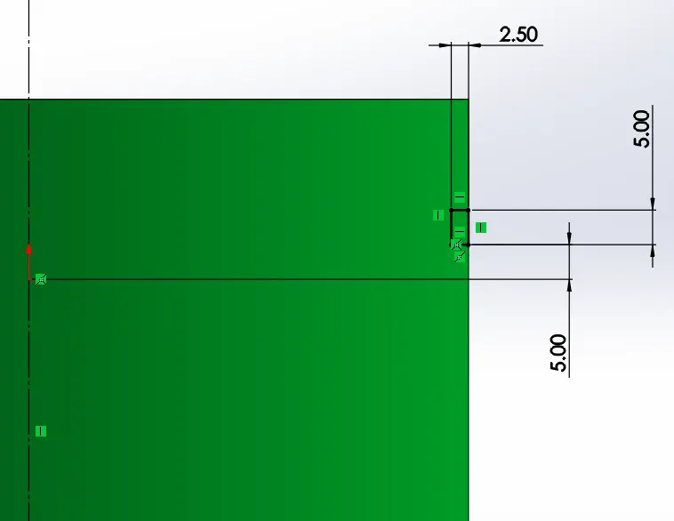
- Select front plane and sketch the below profile shown in image and use revolve extrude cut using that profile and Select the Linear pattern for 3 instances and 10mm distance.
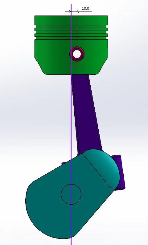
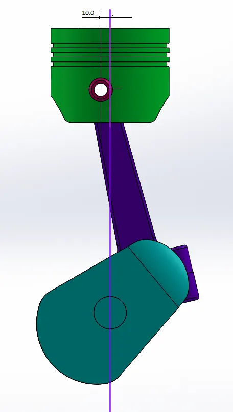
- Select the front plane and sketch a circle of diameter 25.4mm, 40mm below the origin.
In case 1 the center of the circle is vertical with the origin.
In case 2 the center of the circle is 10mm to right of the origin.
In case 3 the circle is 10mm to the left of the origin.
5.Select Right Plane and sketch the profile as shown in below image and use extrude cut through all to remove the material.
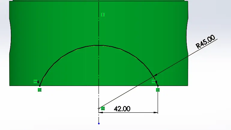
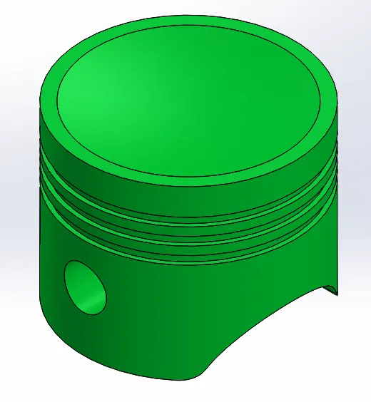
6.Exit sketch and extrude. Keep offset of 30mm.Under Direction 1, Select Up to Surface. Under surface select the outer surface of the piston. Flip the direction and click ok. Mirror this extrusion with front plane as mirror face. Wrist pin rest in this extrusion.
7.Piston head is ready.
Wrist Pin:-
- Open solid works and set metric system to MMGS.
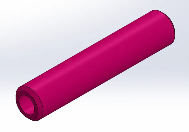
- Select Front plane and sketch two concentric circles of Dia 25.4mm and Dia 36.4mm, use extrude to length 127mm with option mid plane.
- Select the two edge and create chamfer 2.5mmx45 deg.
- Wrist pin is ready.
Connecting Rod:-
- Open solid works and set metric system to MMGS.
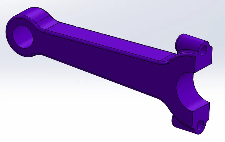
- Select front plane and sketch the below profile shown in image and use extrude of length 30mm with mid plane option using that profile.
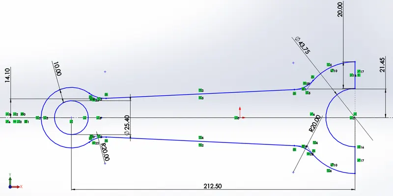
- Select the face of the semicircular part. Sketch two circles of diameter, each whose centre lies on the edge of the rectangular face and vertical to origin. Exit sketch and extrude it by 30mm in the direction towards the other circular face. Select the same rectangular face again and sketch two circle concentric to the previous circles. Exit sketch and make extruded cut of 30mm.Filet the corners of the connecting rod using filet radius of 2.7mm.
- Connecting rod is ready.
End Cap:-
- Open solid works and set metric system to MMGS.
- Select front plane and sketch the below profile shown in image and use extrude of length 30mm with mid plane option using that profile.
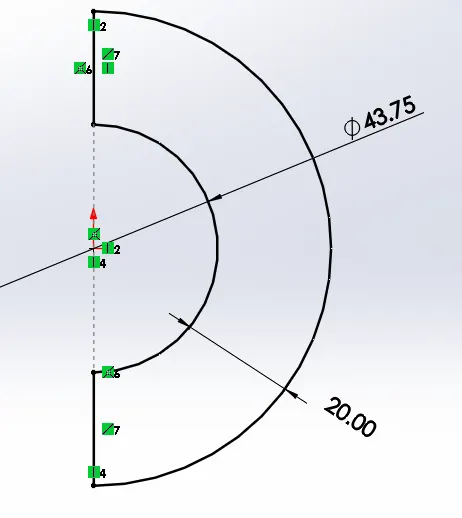
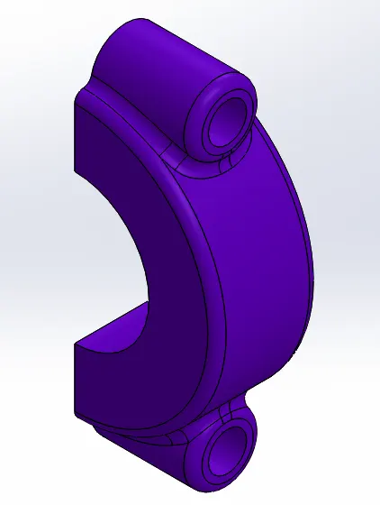
- Select the face of the semicircular part. Sketch two circles of diameter, each whose center lies on the edge of the rectangular face and vertical to origin. Exit sketch and extrude it by 30mm in the direction towards the other circular face. Select the same rectangular face again and sketch two circle concentric to the previous circles. Exit sketch and make extruded cut of 30mm.
- End cap is ready.
Crank:-
- Open solid works and set metric system to MMGS.
- Select front plane and sketch the below profile shown in image and use extrude of length 20mm using that profile. Fillet the corners with radius 25mm.
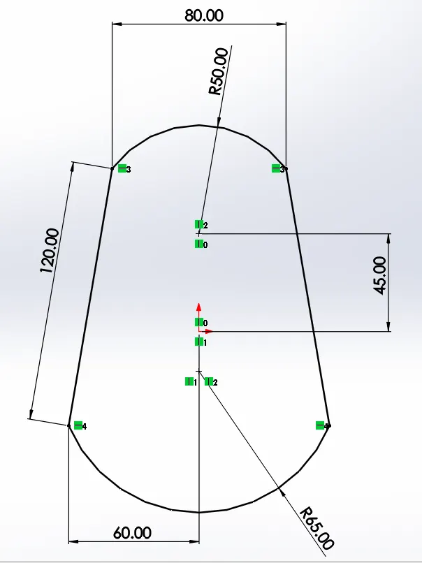
- On one face draw a circle of 43.75mm, 50mm from origin, use extrude of 16mm length.
- On other face draw a circle of 35mm as origin, use extrude of 20mm length.
- Select Right plane and sketch the below profile, use extrude cut to remove the material.
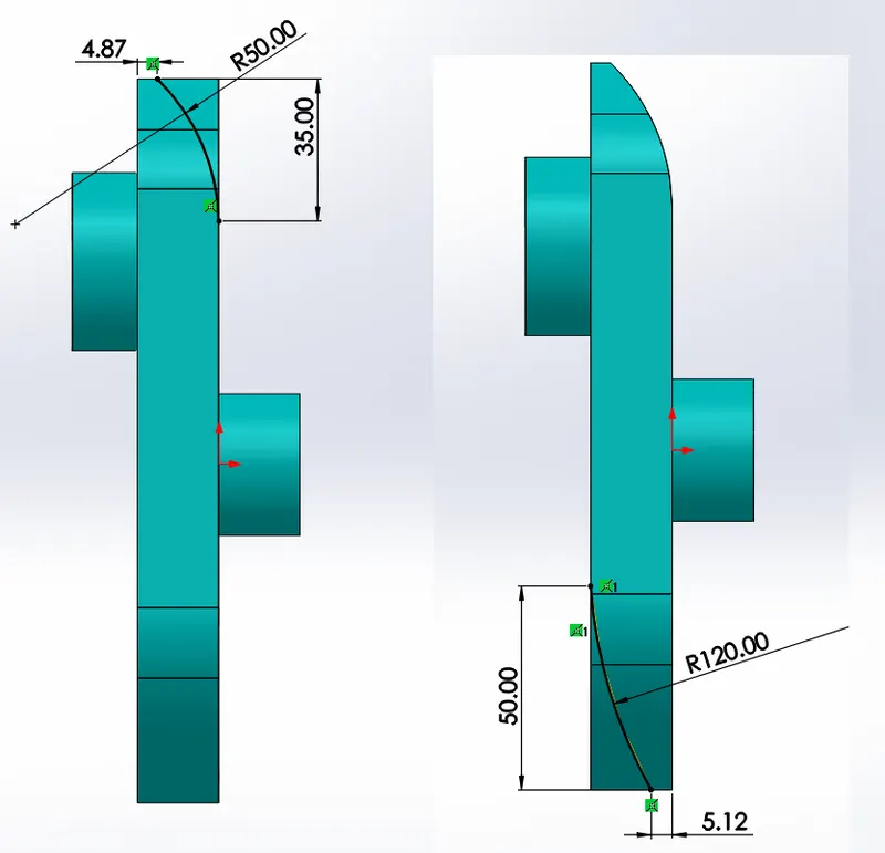
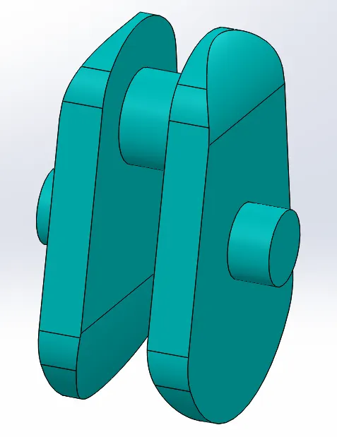
- Mirror the entire body with 43.75mm extruded face.
- Crank is ready.
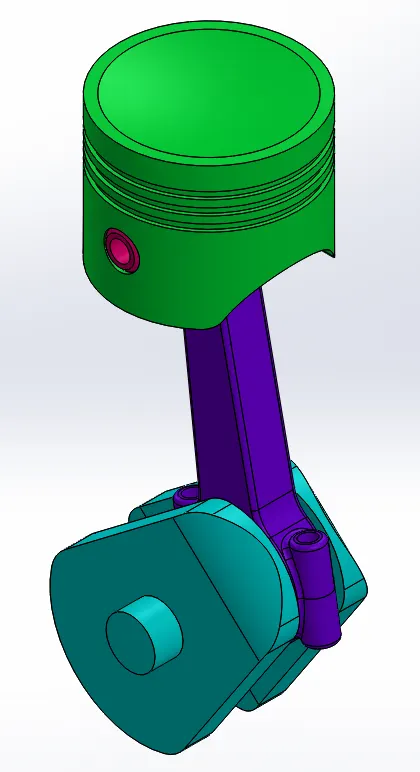
Assembly Construction:-
- Open a new assembly model. Load the crank. View all temporary axis. Right click the crank shaft and select float.
- Coincide the axis of the crank with the Right plane and the Top Plane of assembly.
- Select the Front Plane of the crankshaft and FP of assembly and make the perpendicular distance between them as 36mm.
- Insert the connecting rod and the end cap. Coincide the axis and face of the connecting rod and end cap
- Coincide the axis of the bigger circle of the connecting rod and the axis of the crank shaft.
- Make the perpendicular distance between one face of the connecting rod and one face of the crank shaft as 1mm.
- Insert the wrist pin and the piston head. Coincide the axis and the front lanes of the wrist pin and the piston head.
- Coincide the center axis of the other side of the connecting rod and the piston head. Also coincide the Front Planes of the connecting rod and the piston head.
- Finally coincide the Right planes of the piston head and assembly.
- Assembly is ready.
Motion Analysis Construction:-
- Select Solidworks Add-Ins, click Solidworks motion. Change type of motion study as Motion analysis.
- Select Motor option. Under reference, select axis of crank. Make speed 2000 rpm.
- Go to settings, make frame speed as 7200 fps, select option Allow precise contact.
- Select Contact. Make contact between crank and end cap, crank and connecting rod, connecting rod and wrist pin and wrist pin and piston head. For all the parts select the material option Steel (Dry).
- Enforce gravity, acting in the Y-direction
- Go to the results and plots option and select the Displacement, magnitude and plot linear displacement of the assembly by providing the top face of Piston head.
- Calculate or plot the graph for all the three cases .
- Results are given below for all the three cases.
CASE 1 : -
Graph of Linear Displacement of Piston vs time
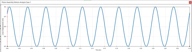
Maximum Displacement is 302mm and Minimum Displacement is 203mm from graph
CASE 2 :-
Graph of Linear Displacement of Piston vs time
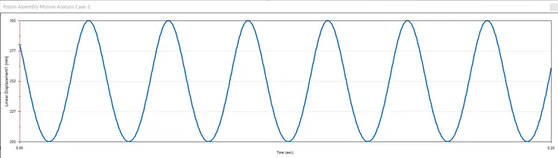
Maximum Displacement is 302mm and Minimum Displacement is 202mm from graph
CASE 3 :-
Graph of Linear Displacement of Piston vs time
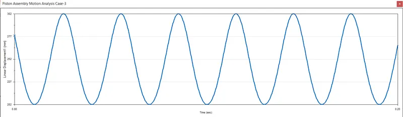
Maximum Displacement is 302mm and Minimum Displacement is 202mm from graph