MBD Simulation on IC Engine Valve Train
Aim:-
To model IC Engine valve parts and assemble to do motion analysis for 2 cases of CAM design.
Introduction on IC Engine Valve Assembly:-
IC Engine Valve assembly is one of the major component in Engine assembly. It consists of 5 parts
- Cam
- Push Rod
- Rocker arm
- Engine valve
- Engine valve Mount
Cam:-
In this assembly we have assumed as a single cam profile. We will have N number of profile in a shaft which is commonly known as Camshaft.
A camshaft is a rotating object usually made of metal that contains pointed cams, which converts rotational motion to reciprocal motion.
Camshafts are used in internal combustion engines to operate the intake and exhaust valves, mechanically controlled ignition systems. Camshafts in automobiles are made from steel or cast iron.
CAM Calculation:-
We have CAM Lift formula from pdf
Cam Lift = (L-R1) +R2 mm
Whereas L= Distance between 2 CAM profile center (mm)
R1= Radius of Bigger CAM Profile (mm)
R2 = Radius of Smaller CAM Profile (mm)
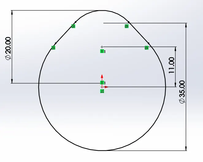
We know Cam Lift in Case 1- 3.5mm
3.5= (L-17.5) +10
Therefore L=11mm
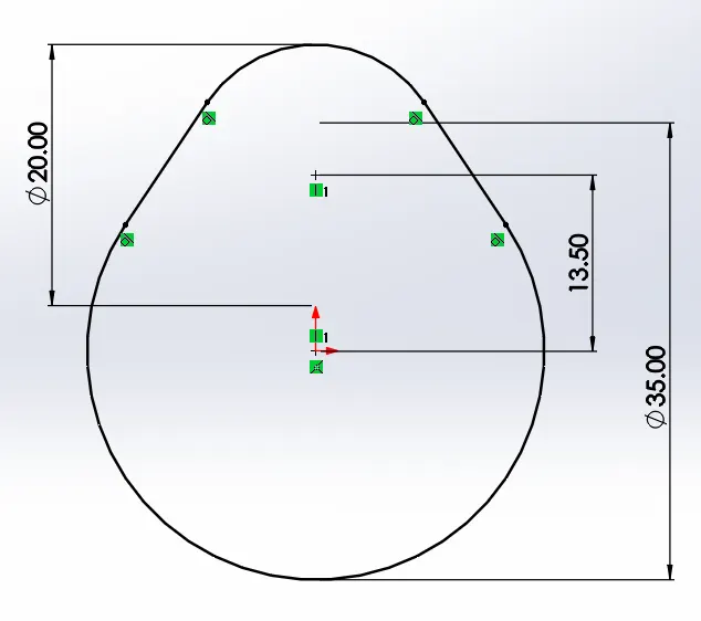
We know Cam Lift in Case 2- 6mm
6= (L-17.5) +10
Therefore L=13.5mm
Push Rod:-
It acts as a bridge between the CAM and Rocker arm, it helps to transmits force from CAM to Rocker arm.
Rocker Arm:-
A rocking arm in an engine, especially one in an internal combustion engine which serves to work a valve and is operated by a pushrod from the camshaft.
Engine Valve:-
Valve is a device to close and open a passage. In motor vehicle engines, two engine valves are used for each cylinder – an intake valve and an exhaust valve.
Intake Valve –
Fuel is allowed to the cylinder by the inlet valve. When closed, the valve seals the combustion space tightly. The valves are usually made of austenitic stainless steel which is a corrosion and heat-resisting material. Inlet valve is subjected to less heat is usually made of nickel-chromium alloy steel.
Exhaust Valve –
The burned gases escape by the exhaust valve. The exhaust valve is usually made of sili-chrome steel which is an alloy of silicon and chromium with unusual resistance to heat.
The valves used in car engines are termed as poppet or mushroom valves. The head of the valve has an accurately ground face with enough margin left to avoid a thin edge. The angular face is ground on the valve head to make an angle of 45° or 30° to match the angle of the valve seat in the cylinder head. Spring retainer lock grooves are provided at the end of the valve stem.
Model Geometry Construction:-
CAM:-
1) Open solid works and set metric system to MMGS.
2) Select front plane and sketch the below profile and use extrude of 10mm using that profile for CASE-1.
3) Select front plane and sketch the below profile and use extrude of 10mm using that profile for C ASE-2.
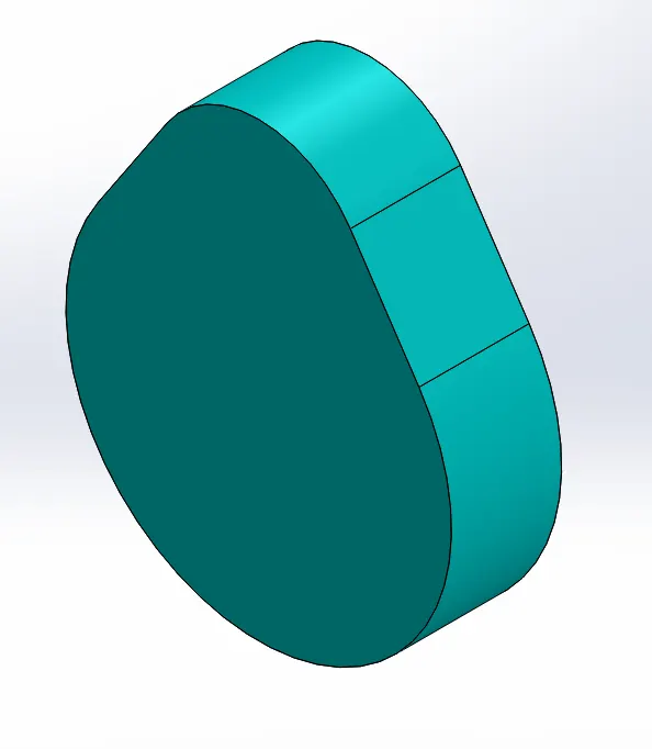
4) CAM is ready.
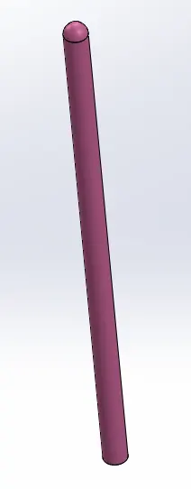
Push Rod:-
1) Open solid works and set metric system to MMGS.
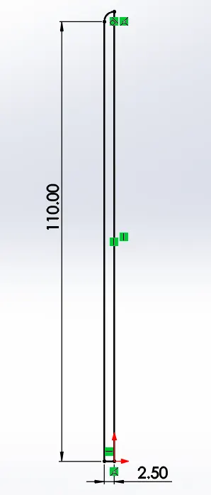
2) Select front plane and sketch the below profile and use extrude revolve using the vertical line near to origin for axis selection using that profile.
3)Push rod is ready.
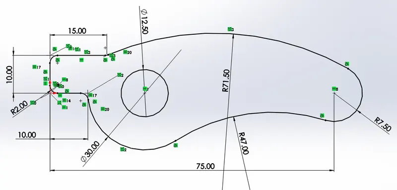
Rocker Arm:-
1) Open solid works and set metric system to MMGS.
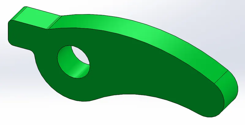
2) Select front plane and sketch the below profile and use extrude of 10mm using that profile.
3) Rocker arm is ready.
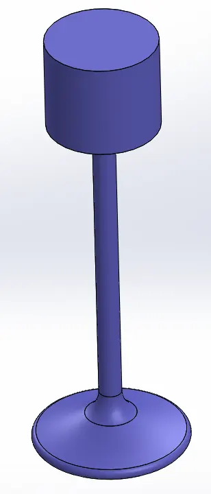
Engine Valve:-
1) Open solid works and set metric system to MMGS.
2) Select front plane and sketch the below profile and use extrude revolve using the vertical line near to origin for axis selection using that profile.
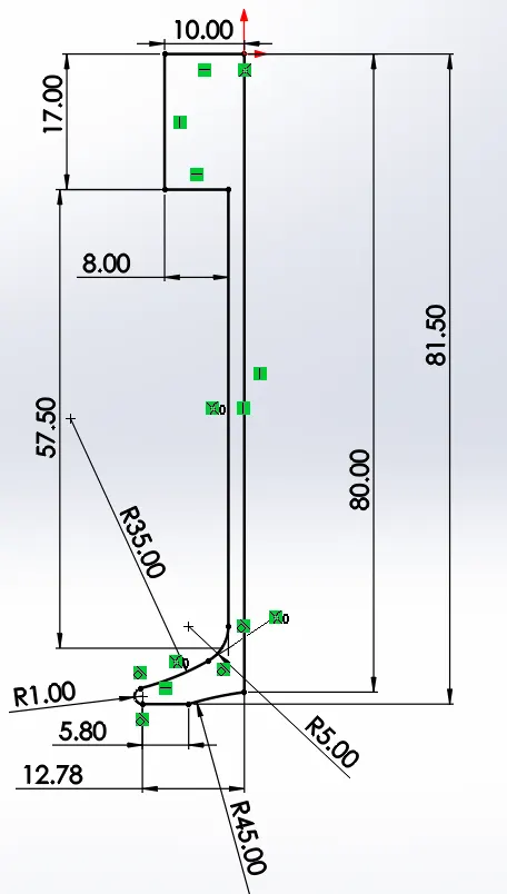
3) Engine valve is ready.
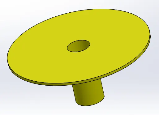
Engine valve mount:-
1) Open solid works and set metric system to MMGS.
2) Select front plane and sketch the below profile and use extrude revolve using the axis near to origin for axis selection using that profile.
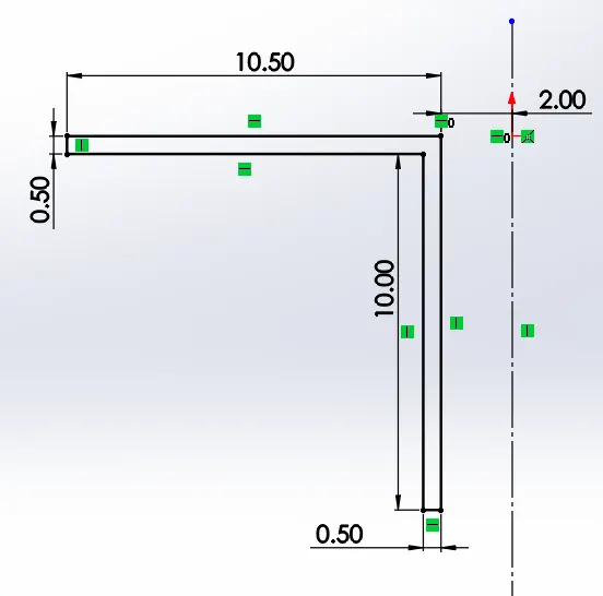
3) Engine valve mount is ready.
Assembly Construction:-
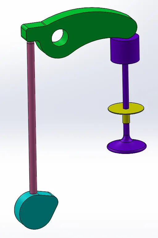
- Open a new assembly model. Insert the cam first. Right click on the cam and select Float option. Click on the view temporary axis option.
- Insert all other parts.
- Coincide the center axis of the rocker arm and the Right Plane of the assembly. Then coincide its center axis with the Top Plane of the assembly. Finally coincide its Front Plane with the Front Plane of the assembly.
- Coincide the Front Plane of the Cam with the Front Plane of the assembly.
- Coincide the center axis of the Push Rod with the Front Plane of the assembly.
- Coincide the center axis of the Engine Valve with the Front Plane of the assembly.
- Coincide the center axis of the Engine Valve Mount with the Front Plane of the assembly.
- Make the axis of push rod distance with the Right Plane of the assembly 20mm.It should be to the left of the Right Plane.
- Make axis of cam distance with the Right Plane of the assembly 20mm.It should be to the left of the Right Plane.
- Make axis of Engine valve mount distance with the Right Plane of the assembly 50mm. It should be to the right of the Right Plane.
- Select the top face of the Valve Mount and make distance between with the Top Plane of the assembly 60mm. Then coincide the center axis of the Valve and the Valve Mount. Move the valve in such a way that it fits into the valve mount.
- Arrange the mechanism in such a way that push rod is above cam, rocker arm is above push rod, valve is below rocker arm (other side).
- Set the Perpendicular distance between the Top Plane of Assembly and the central axis of cam as 130mm.
- Again move the parts such that no part is meshing with another.
- Click on the Move Contacts option. Select Physical Dynamics. Move the parts such that they just touch each other.
- Assembly is ready.
Motion Analysis Construction:-
- Select Solidworks Add-Ins, click Solidworks motion. Change type of motion study as Motion analysis.
- Select Motor option. Under reference, select axis of cam. Make speed 1500 rpm.
- Go to settings, make frame speed as 7200 fps, select option Allow precise contact.
- Select Contact. Make contact between cam and push rod, push rod and rocker arm and rocker arm and Engine valve mount. For all the parts select the material option Steel (Dry).
- Select the spring option. For reference edges, select the bottom edge of the tip of the Engine valve and the top edge of the Engine valve mount. Make Spring Constant 10N/mm and Free Length of 45mm
- Select all the parts, right click and select Material---->Edit Material. In the Material Dialogue Box, search for Cast Carbon Steel and click Apply.
- Reduce end time to 0.2s and click Calculate.
- Select the results and plots option and select the Displacement , magnitude and plot Linear displacement of Engine valve by providing the bottom face of Engine valve.
- Select the results and plots option and select the Forces, magnitude and plot Contact force between Cam - Push rod , Push Road -Rocker arm and Rocker arm-Engine Valve by providing the coresponding contact face.
- Results are plotted and given below for both Case 1 & Case 2.
Results & Graphs :-
CASE 1:-
1) Linear displacement of Engine Valve
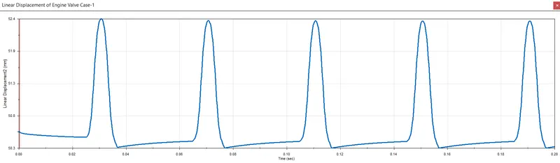
Maximum value 52.4mm and Minimum value 50.3mm
2) Contact force between Cam and Push rod - (Magnitude)
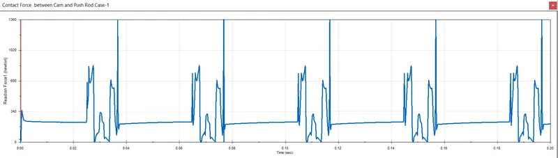
Maximum Force value is 1365 N
3) Contact force between Push rod and Rocker arm - (Magnitude)
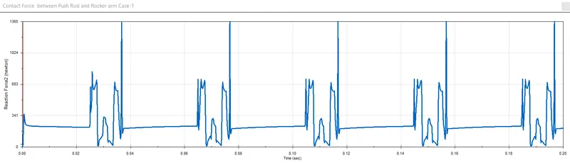
Maximum Force value is 1365 N
4) Contact force between Rocker arm and Engine valve- (Magnitude)
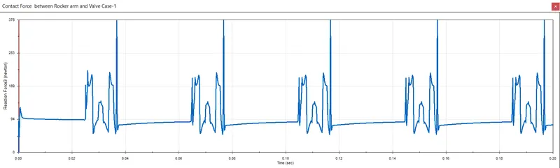
Maximum Force value is 1365 N
5) Contact force between Rocker arm and Engine valve - X direction
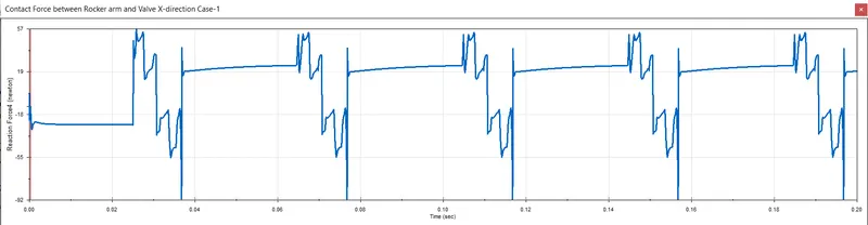
In X direction Maximum force is 57N and Minimum Force is -92N
CASE 2:-
1) Linear displacement of Engine Valve
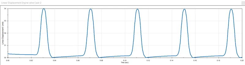
Maximum value 54mm and Minimum value 50mm
2) Contact force between Cam and Push rod - (Magnitude)
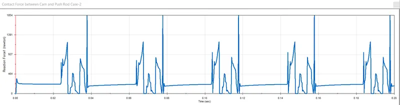
Maximum Force value is 1854 N
3) Contact force between Push rod and Rocker arm - (Magnitude)
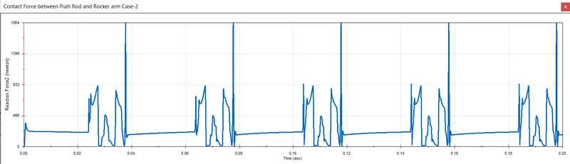
Maximum Force value is 1864 N
4) Contact force between Rocker arm and Engine valve- (Magnitude)
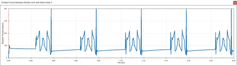
Maximum Force value is 1365 N
5) Contact force between Rocker arm and Engine valve - X direction
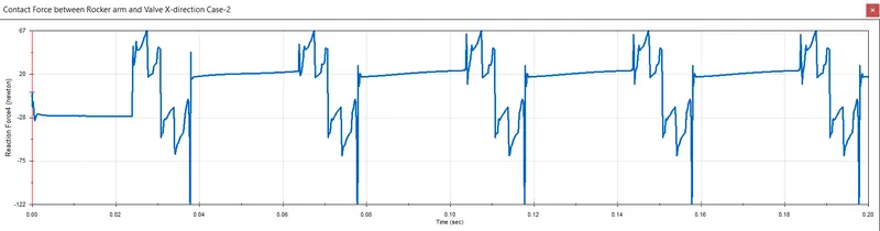
In X direction Maximum force is 67N and Minimum Force is -122N
Conclusion:-
We know Magnitude is sum of forces exerted on a body in both X and Y direction.
If we calculate the force exerted on X direction, definitely there will be a reaction force also, so the force value varies with magnitude.