Planetary Gear
Introduction
An planetary gearset (also known as a epicyclic gear train) consists of two gears mounted so that the center of one gear revolves around the center of the other. A carrier connects the centers of the two gears and rotates to carry one gear, called the planet gear or planet pinion, around the other, called the sun gear or sun wheel. The planet and sun gears mesh so that their pitch circles roll without slip. A point on the pitch circle of the planet gear traces an epicycloid curve. In this simplified case, the sun gear is fixed and the planetary gear(s) roll around the sun gear.
Planetary gear transmission (PGT) is widely used in the automobiles, helicopters and marine applications.
PGT is more advanced than counter-shaft drive because of its higher torque-to-weight ratio, compactness and reduced noise.
Calculation For the Study
Given Details : -
Ring gear-1 , Sun Gear -2 , Planet gear -4
Ring gear Specification
Module-2.5 , No. of Teeth Zr-46
Spur gear Specification
Module-2.5 , No. of Teeth Zs-14
For Planet gear No. of teeth Zp We have the formula --> Zs+2Zp=Zr
14+2Zp=46 à Zp=16
Module remains the same m=2.5
PCD = Module (m) * No. of Teeth
Assumption :
For all gears the thickness will be 25mm.
Carrier is created according to the input of Spur and Planet gear details.
Gear Geometry
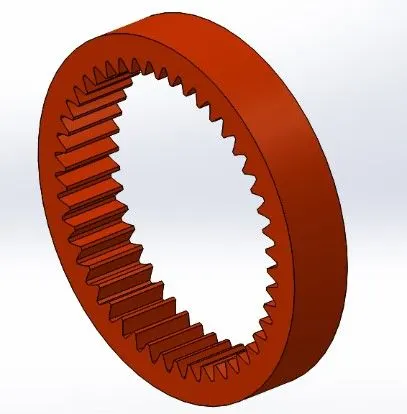
Ring Gear :
No. of teeth - 46
Module - 2.5
PCD – 115mm
Outside Diameter – 140mm Assume for better view
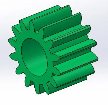
Spur Gear :
No. of teeth - 14
Module - 2.5
PCD – 35mm
Shaft Diameter – 20mm
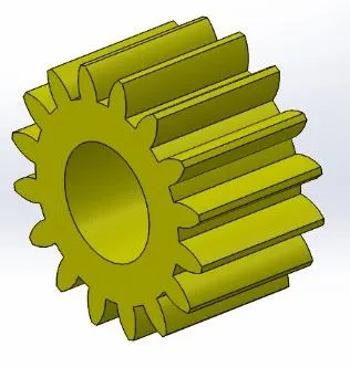
Planet Gear :
No. of teeth - 16
Module - 2.5
PCD – 40mm
Shaft Diameter – 20mm
Carrier:
- In right plane sketch the Sun gear PCD in the centre and Four Planet gear PCD tangent to the Spur gear PCD. Radius given between the planet gear is 70mm dia.
- Trim the inside circle so that it look similar to sketch below for carrier main body and a 20mm dia material removed to the width of 20mm for the centre axis of main body
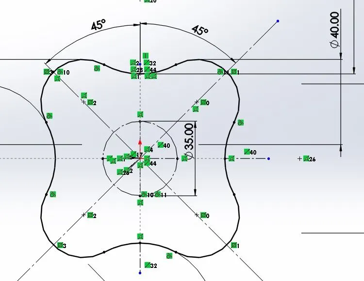
- For Planet gear shaft create 4 shaft diameter of 20mm with 25mm extrusion in the centre of the planet gear PCD on the carrier main body.
- For the input shaft same 20mm diameter 40mm extrusion is given on the back face of the main carrier body, then the model looks like below.
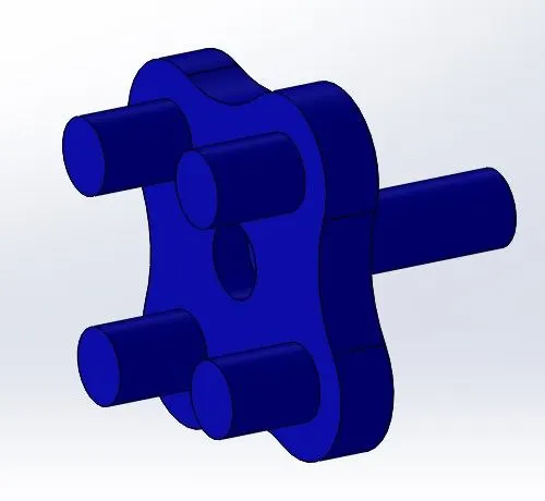
Assembly Input
- Open a new assembly, Export the carrier model first and change to float
- Coincide the right plane of the assembly with the right plane of the carrier and Coincide the front and top plane of the assembly with the central axis of the carrier.
- Go to design library. Select standard as ANSI Metric. Select Power Transmission. Click Gears.
- Under gears, select spur gears and click Insert or drag into assembly provide the details, insert another 4 planet gears which saved as same part provide details and insert ring gear repeat the same step and provide details.
- Coincide the central axis of each planet gear with the axis of each 25mm extrusion in in carrier body and Coincide the front face of the planetary gear with the front face of the 25mm extrusion in carrier body.
- Coincide the center axis of the sun gear with the center axis of the carrier and coincide the front face of the sun gear with the front face of any planet gear.
- Coincide the central axis of the ring gear with the central axis of the carrier and coincide the front face of the ring gear with the front face of the planetary gear.
- Go to the front view and move all the components till no two components overlaps with each other. Now the assembly constraints is completed.
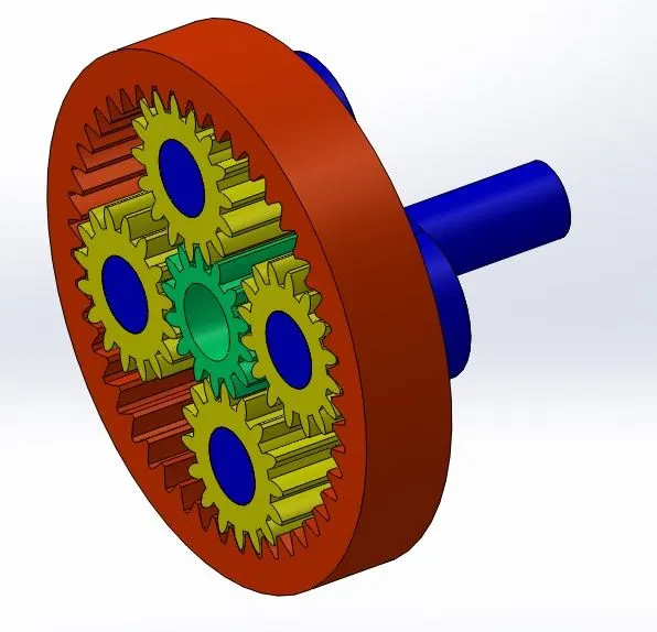
All assembly and single part Models are attached.
Motion Analysis Study
Case 1 :
Sun Gear – Input / Carrier – Output / Ring gear - Fixed
- Go to SolidWorks Add-Ins and select SolidWorks Motion, Change the type of motion study from Animation to Motion Analysis in the new motion study.
- Fix the ring gear.
- Select the motor option, select the inner circle of the sun gearand give speed 200rpm
- Select Contact option , default solid contact , Make contact between the sun gear and all planet gears and between the planet gears and the ring gear by selecting the front face of respective parts and assume the components material Steel(dry).
- Calculate the results , change the time range to 20 sec.
- Select the results and plots option and select the angular velocity , magnitude and plot angular velocity of the carrier by providing the contact face of Spur gear and planet gear.
Result : Maximum velocity went to 1809 deg/sec
Attached plot and analysis animation.
Case 2 :
Sun Gear – Fixed / Carrier – Output / Ring gear - Input
- Go to SolidWorks Add-Ins and select SolidWorks Motion,Change the type of motion study from Animation to Motion Analysis in the new motion study.
- Fix the Sun gear.
- Select the motor option, select the inner axis of the Ring gear and give speed 200rpm
- Select Contact option, default solid contact, Make contact between the Ring gear and all planet gears and assume the components material Steel(dry).
- Calculate the results , change the time range to 20 sec.
- Select the results and plots option and select the angular velocity , magnitude and plot angular velocity of the carrier by providing the contact face of Ring gear and planet gear
Result : Maximum velocity went to 1784 deg/sec
Attached plot and analysis animation.
Case 3 :
Sun Gear – Input / Carrier – Fixed / Ring gear - Output
- Go to SolidWorks Add-Ins and select SolidWorks Motion,Change the type of motion study from Animation to Motion Analysis in the new motion study.
- Fix the Carrier.
- Select the motor option, select the inner axis of the Spur gear and give speed 200rpm
- Select Contact option, default solid contact, Make contact between the Ring gear and all planet gears and Spur gear and all planet gears assume the components material Steel(dry).
- Calculate the results, change the time range to 20 sec.
- Select the results and plots option and select the angular velocity , magnitude and plot angular velocity of the Ring gear by providing the contact face of Spur gear and planet gear
Result : Maximum velocity went to 2371 deg/sec
Attached plot and analysis animation.