Week 4- Meshing of Backdoor Challenge
Week 4- Meshing of Backdoor Challenge
Aim: To mesh the backdoor geometry of a car by following the given quality parameters
Given quality parameters
| S.N | Quality Criteria | Value |
| 1 | Aspect Ratio | 5 |
| 2 | Skewness | 45 |
| 3 | Warping | 15 |
| 4 | Taper | 0.5 |
| 5 | Min. Length | 3 Units |
| 6 | Max. Length | 7 Units |
| 7 | Min angle Quad | 45 |
| 8 | Max angle Quad | 135 |
| 9 | Min angle Tria | 30 |
| 10 | Max angle Tria | 110 |
| 11 | Tria % | 15 |
| 12 | Target element length | 5 |
Given model
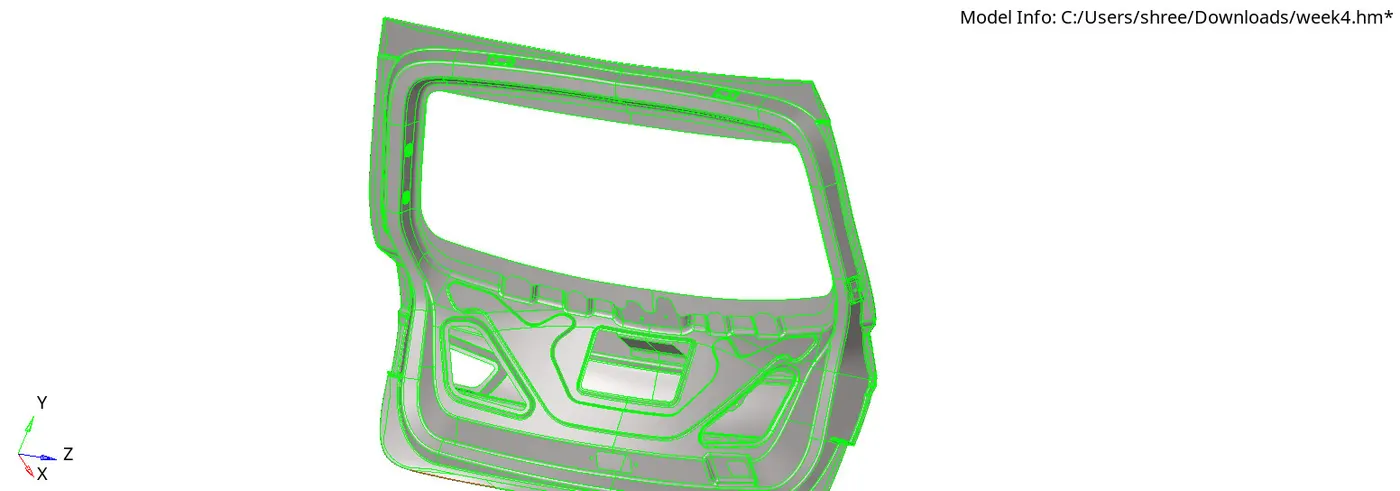
procedure for the given model
1) Import Geometry Model
● Navigate to "Import" in the software interface.
● Select the "Import Geometry" option.
● Choose the file type "IGS" from the available options.
● Click on the "Import" button to initiate the import process.
● After importing the model, position the mouse cursor on the graphics panel.
● Press the key "F" on the keyboard to fit the model to the graphical area,
2) Geometry clean-up
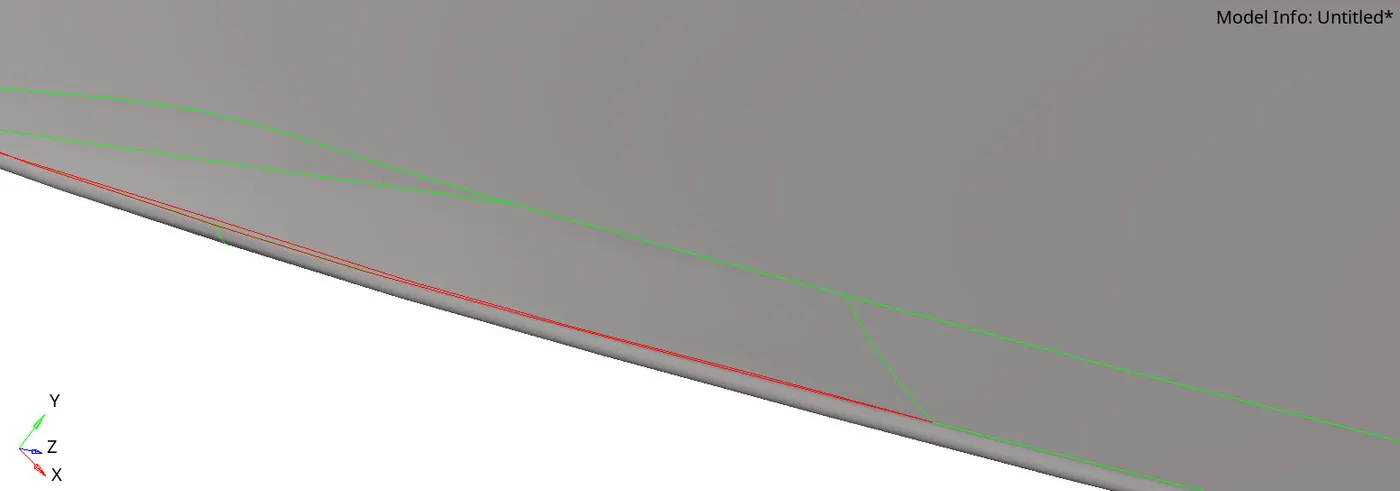
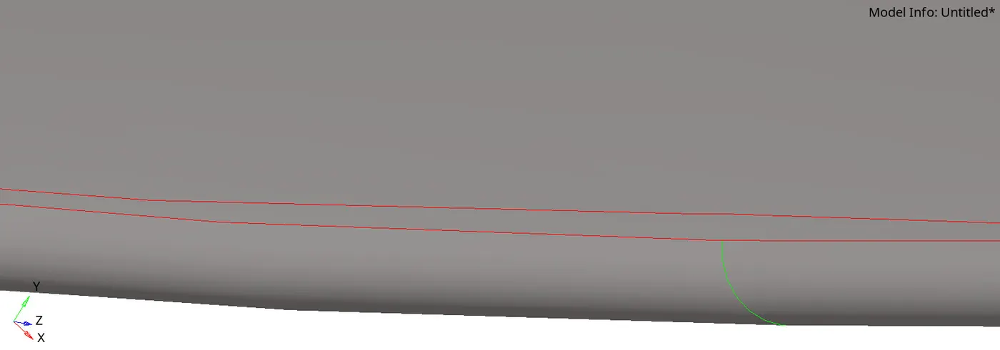
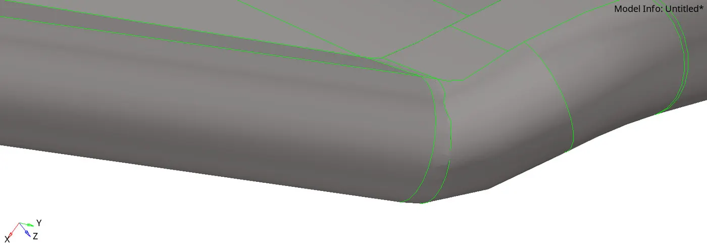
1. Navigate to Geometry Color Mode:
- Access the "Topo" option to switch to geometry color mode for visualizing model details effectively.
2. Inspect for Free Edges:
- Scan the model for any free edges, ensuring all edges are appropriately connected to surfaces.
3. Address Missing or Duplicate Surfaces:
- Utilize "Quick Edit" to identify and rectify any missing or duplicated surfaces for model completeness.
4. Delete Solids if Present:
- Confirm if solid components exist and delete them to streamline the model for meshing operations.
3) Mid surface extraction
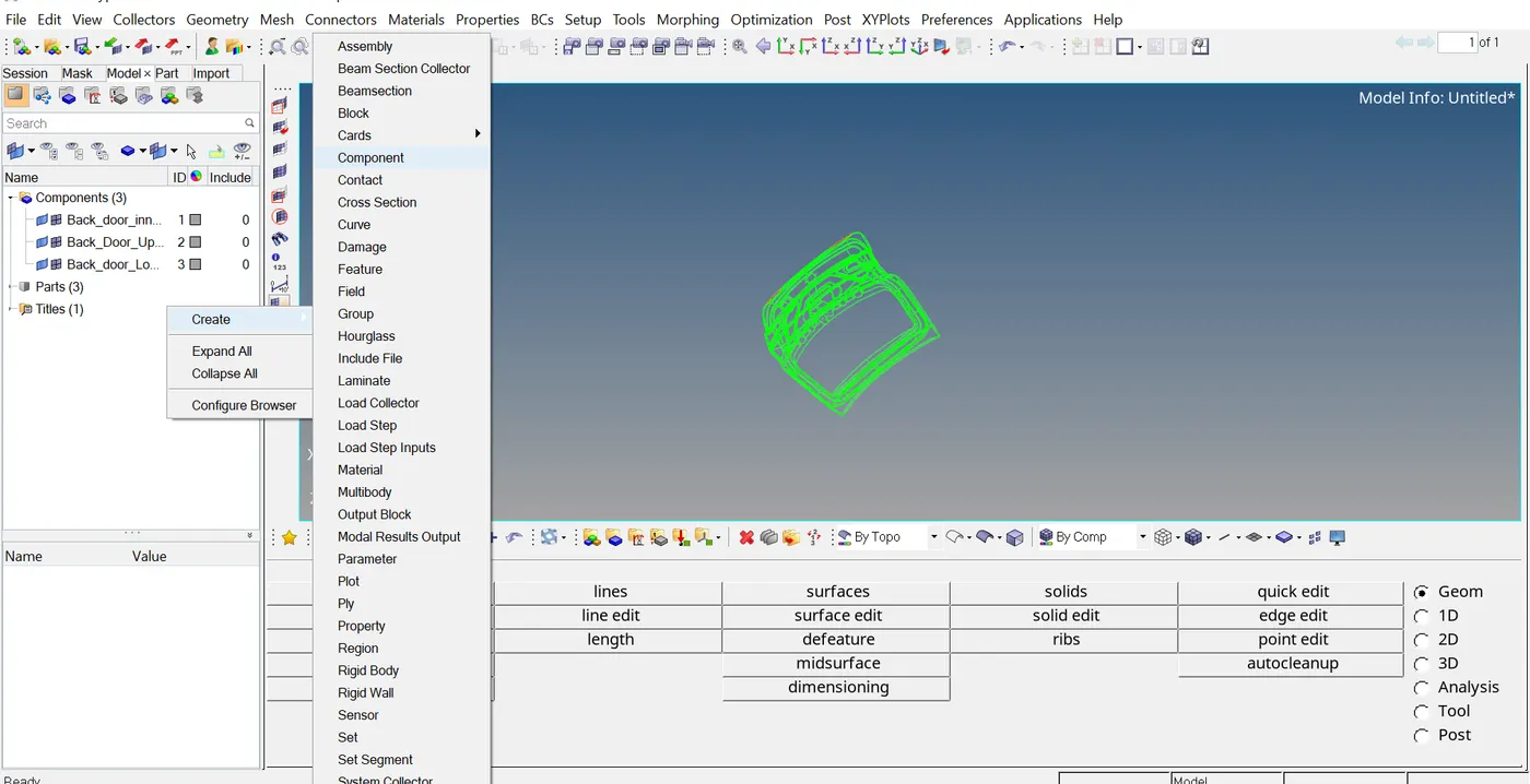
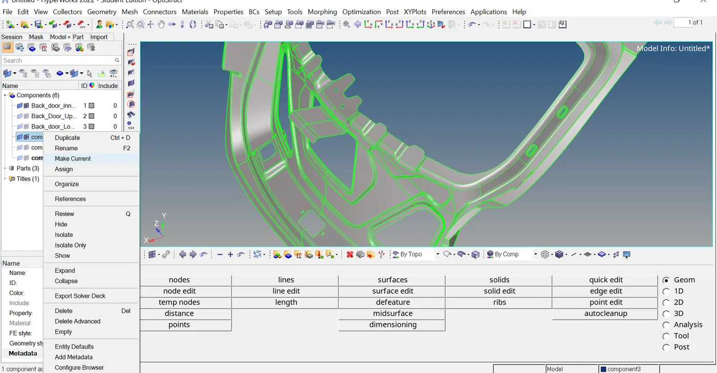
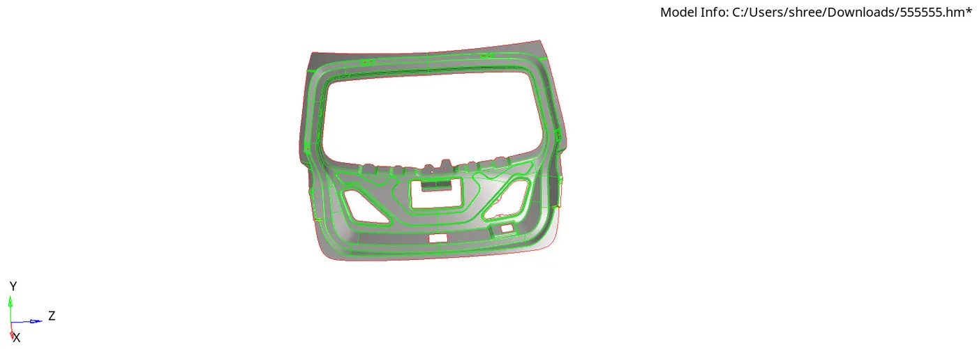
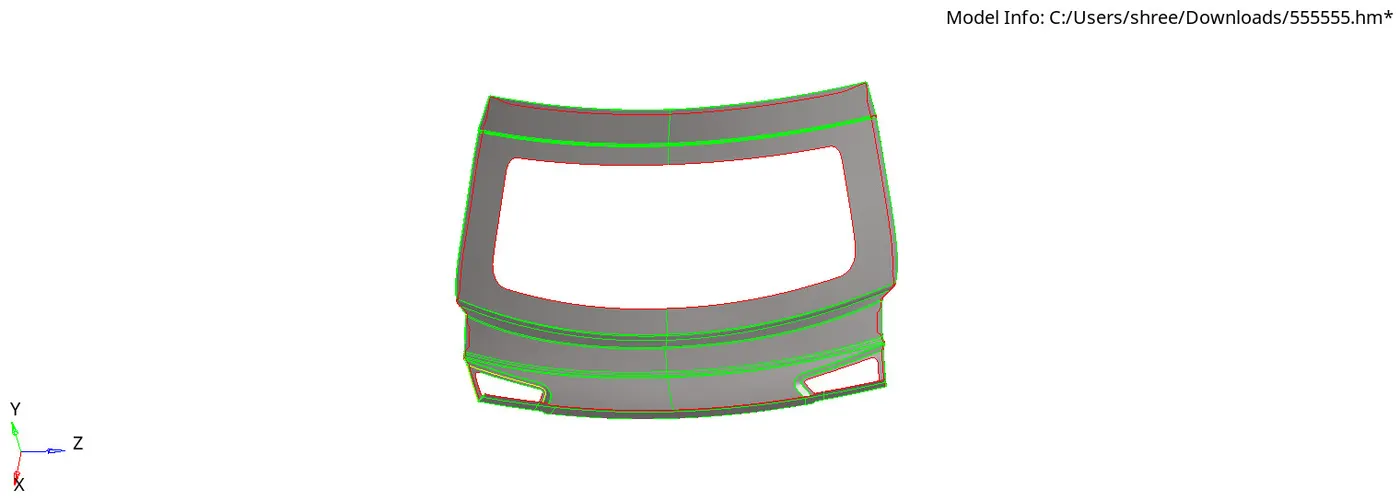
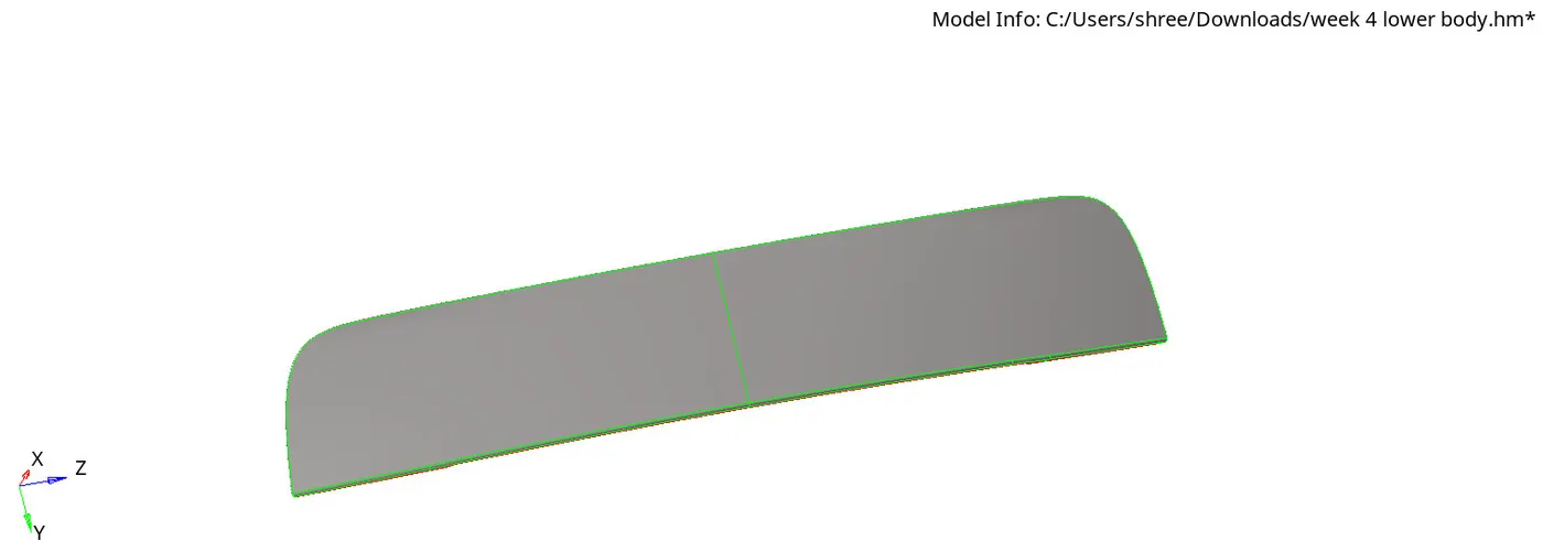
● Now, before extracting the mid-surface, the model, which consists of three components, needs to be separated into individual components. This separation facilitates the mid-surface extraction process.
● Next, select the specific component from which you want to extract the mid-surface.
● Navigate to Geometry > Mid Surface > Select Surface > Automid > Extract.
4) Quality Parameter
Add the provided quality criteria values to the criteria file to establish mesh quality standards.
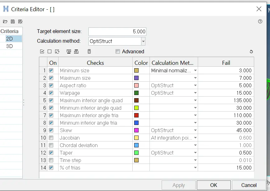
5) Geometry clean-up for mid-surface
● Use visualization tools (topo mode or weir frame mode) to identify any missing surfaces, free edges, extended surfaces, or duplicate surface formations.
● Quick Edit: Go to Geometry > Quick Edit.
● In the Quick Edit window, select the correction options based on the errors you identified.
● For missing surfaces, create new surfaces using the appropriate tools.
● For free edges, extend or connect the edges to form closed surfaces.
● For extended surfaces, trim or cut the surfaces to the desired size.
● For duplicate surface formations, delete or merge overlapping surfaces.
OR
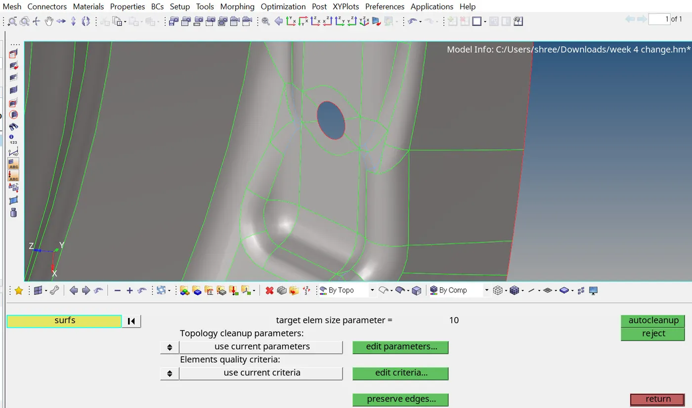
● Go to Geometry > Auto Cleanup.Configure the Auto Cleanup settings to focus on errors related to the Target Element Length. Specify the desired target element length for surfaces in the Auto Cleanup settings. Run the Auto Cleanup process. Hyperwork will automatically correct geometric errors while considering the specified target element length.
6) Mesh generation
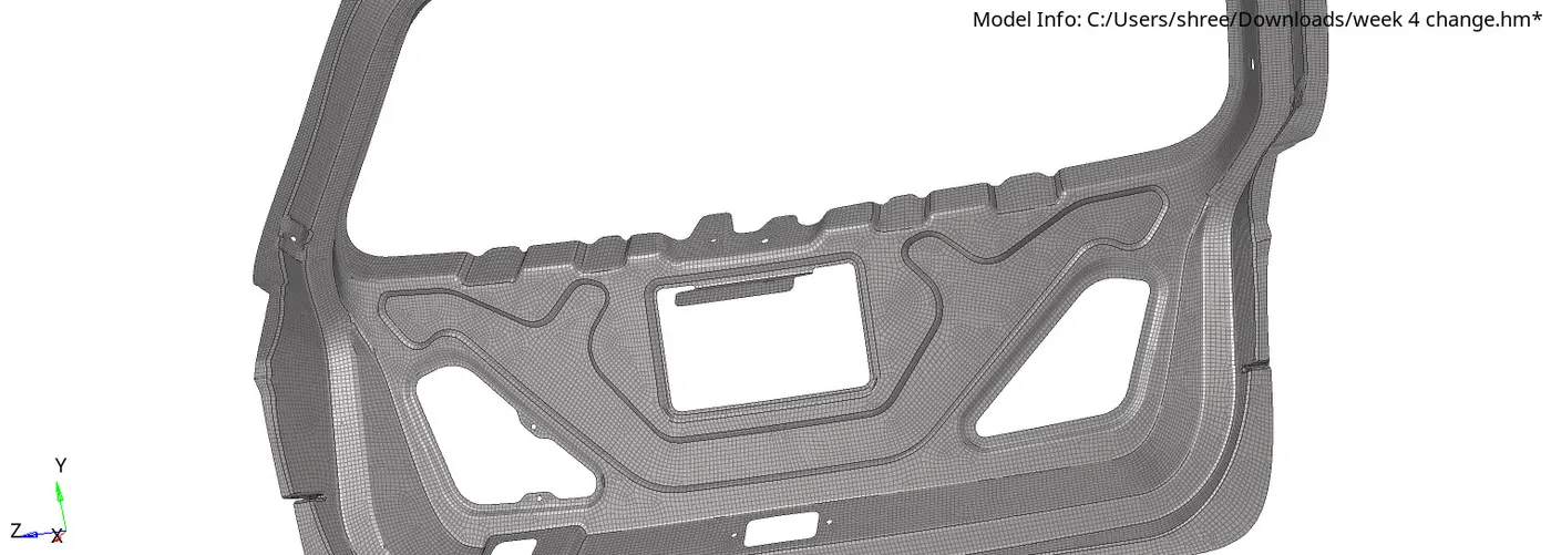
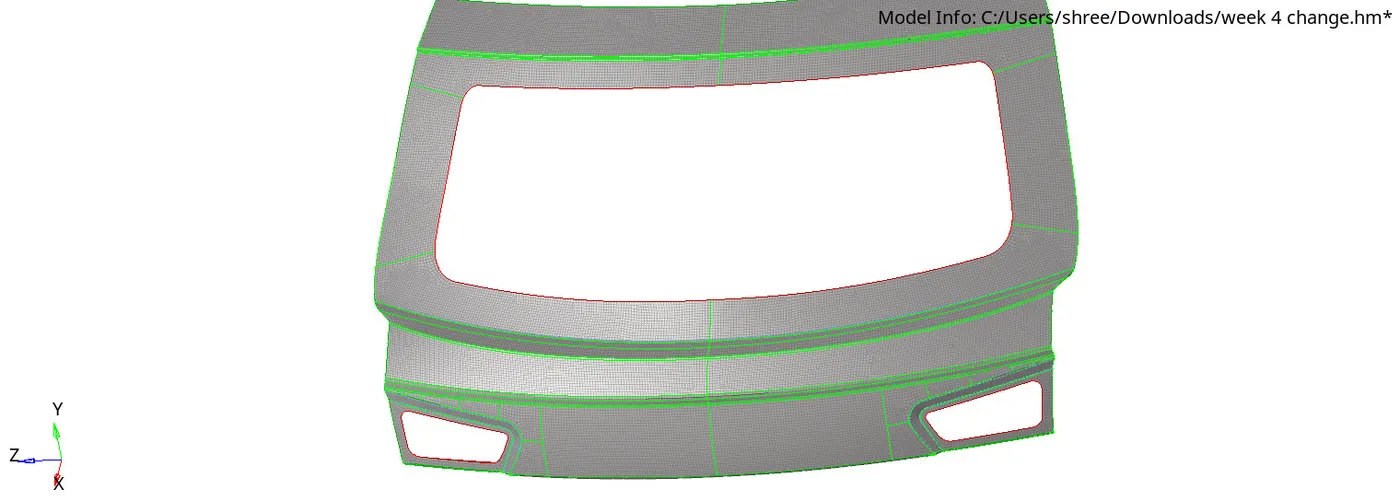
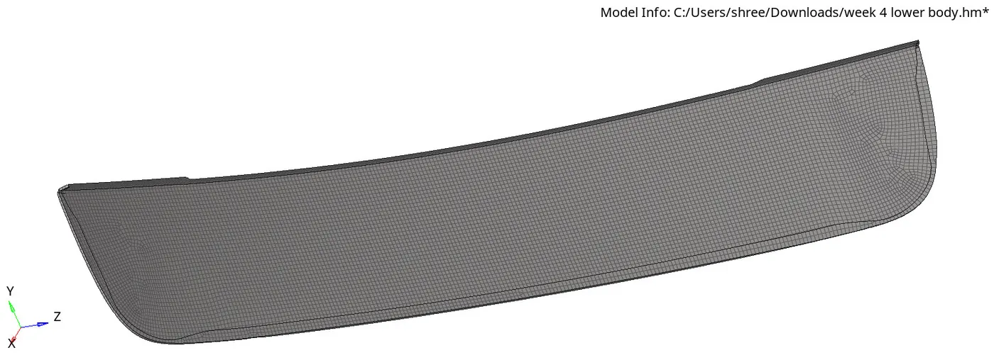
To manually mesh each surface of the component with quad elements in Hyperwork, follow these steps:
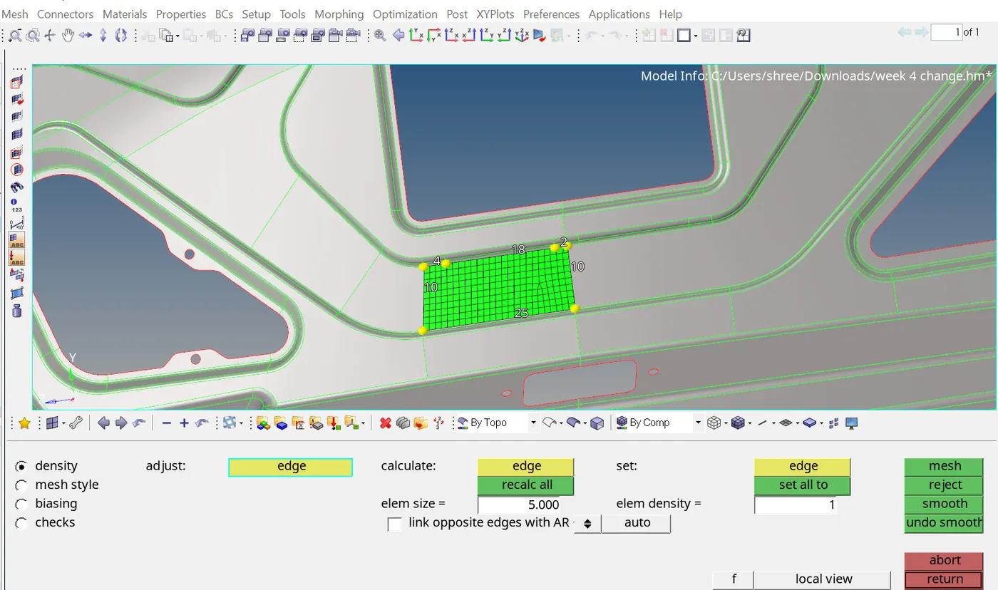
- Select 2D Meshing: Navigate to the 2D Meshing section in Hyperwork.
- Automesh: Click on the Automesh option to initiate the meshing process.
- Select Surface: Choose the surface of the component that you want to mesh manually. You can do this by clicking on the surface in the graphics area or selecting it from the component tree.
- Select Quad Element: In the meshing parameters, specify that you want to use quad elements for the mesh. This ensures that the elements generated will be quadrilateral in shape.
- Element Size: Set the desired element size for the mesh. This determines the size of the elements that will be generated on the surface. You can specify the element size based on your analysis requirements.
- Mesh Generation: Once the parameters are set, proceed to generate the mesh for the selected surface. Hyperwork will create a quad mesh based on the specified element size.
- Repeat for Each Surface: Repeat this process for each surface of the component that you want to mesh manually. Select the surface, adjust meshing parameters if necessary, and generate the mesh using quad elements.
7) check for mesh elements
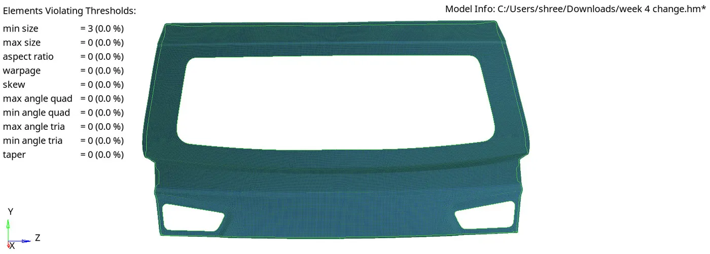
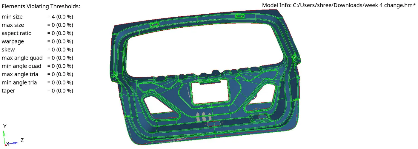
- Review and Validate: After meshing each surface, review the meshes to ensure they meet your quality and accuracy requirements
- Trie to minimize the failed elements and here some failed elements were found because of the minimum size as shown above in figure
- To minimize the failure element make it smooth
- go to 2D >quality index >choose the smooth option> set failed mode >select the surface > Smoot
- use the element cleanup panel to perform automatic cleanup of 2D elements based on the element quality criteria from the Quality Index panel or a separate criteria file
Note
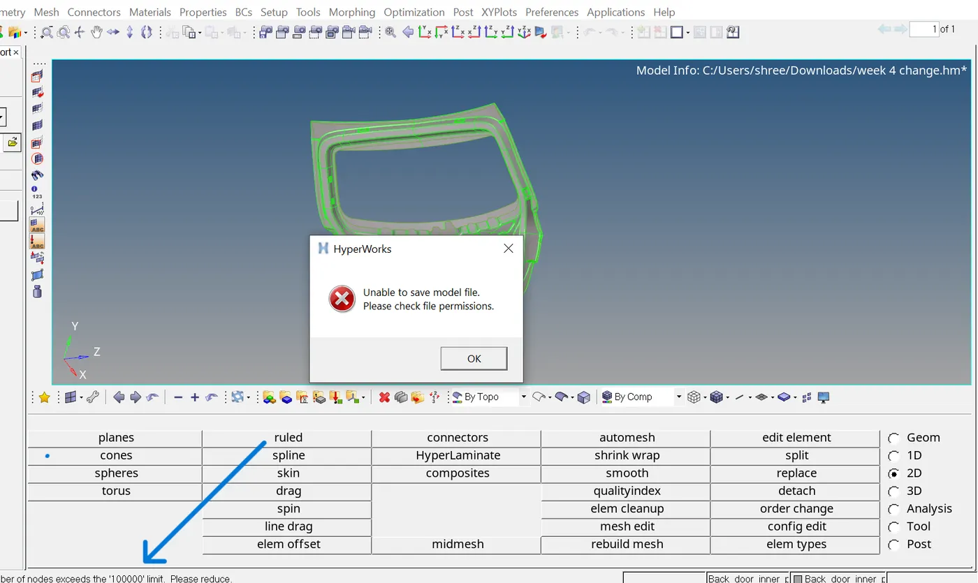
here I am uploading one component separately out of three components because in the Hyperwork software student version, the number of mesh elements is limited to below 100,000. In the given challenge model, all components mesh elements reach above 100,000 (for example, 101,000 elements were generated without any duplicates). and I am 3 times work from scratch it's not reached below the limit
link of the components
upper and inner back door components
https://drive.google.com/file/d/1AEJrw3MsetJ1ZYAyvBZBe3A46BIOj1is/view?usp=drive_link
lower component
https://drive.google.com/file/d/1UVmczpODU7p9MJ1uXzHPPbsxaV6L_Jdl/view?usp=drive_link