Week - 4 - 2D meshing for Plastic components
Week - 4 – 2D Meshing For Plastic Components
For the given plastic bottle cap model check for geometrical errors and take the mid-surface techniques. PID and Thickness assignment has to be done for the entire mid surface. Mesh the same with the given elemental quality criteria
AIM: For the given plastic bottle cap model check for the geometrical errors and take the mid-surface techniques. PID and Thickness assignment has to be done for the entire mid surface. Mesh the same with the given elemental quality criteria
1. Quality criteria
Every product that has been produced will go through a set of quality checks. If the quality check fails other steps like boundary condition & applying loads will not be feasible,
The criteria provided are mentioned below in the table
S.N | Quality Criteria | Value |
1 | Aspect Ratio | 3 |
2 | Skewness | 45 |
3 | Warping | 15 |
4 | jacobian | 0.7 |
5 | Min length | 0.5 |
6 | Max length | 3 |
7 | Min angle quad | 45 |
8 | Max angle quad | 135 |
9 | Min angle tria | 20 |
10 | Max angle tria | 120 |
11 | Tria % | 15 |
The target element length =1 Unit
2. CAD Model
The provided CAD model of plastic bottle cap components
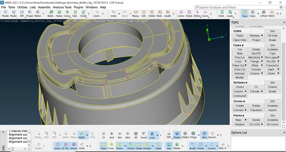
Steps involve
- To check all the geometry errors and rectify them
- To check the thickness of all the components in the model
- To extract the mid surface from the geometry
- To generate a mesh with good flow in the given quality criteria
PROCEDURE:
1) Check For Undefined Material:
< PROPERTIES> Here we can observe how many components are there in the geometry according to how many property IDs are present< MATERIALS> Here how many material properties are available and whether are they defined or not. if not we have to ONN the mark sign to define or undefined it. Then check for undefined materials in the checks manager.
2) Check The Geometry:
Here we have to check the geometry issue with CAD before going to mesh it.
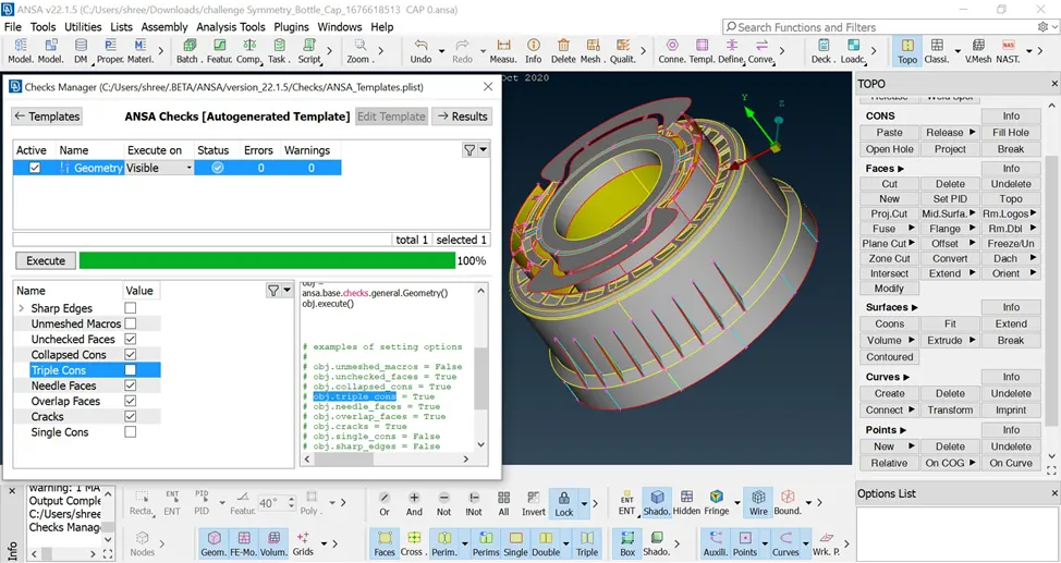
It is an important stage.<< CHECKS> GEOMETRY >>On checking these PID's for geometry. We didn't get any geometrical issues.
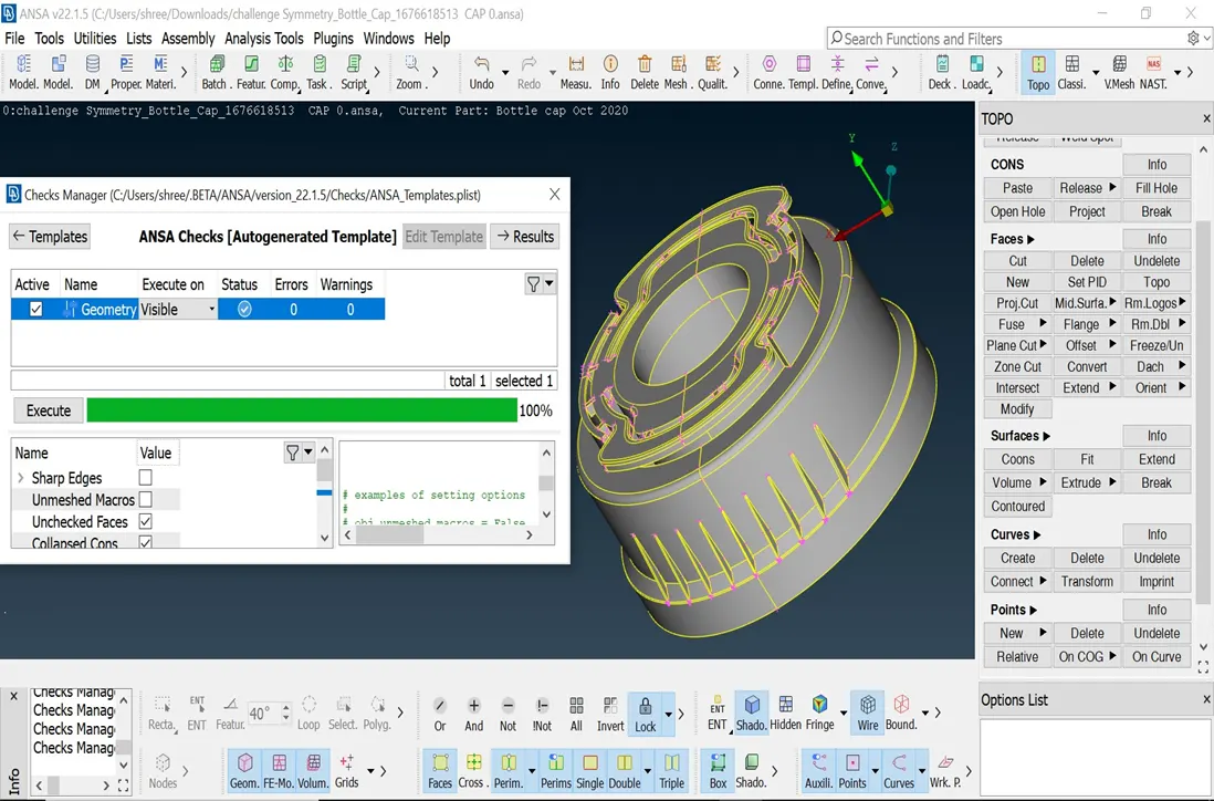
3) MIDSURFACING
There are two methods by which mid surfaces can be extracted 1. auto mid, 2 middle method For this project we only going to use manual mid surfacing for that << FACES>OFCET >> and select the region where the mid surface is to be extracted.
· The picture below shows the mids of the plastic bottle cap hear some geometry of the model difficult to extract the mid surface
· Hear we transformation option in the picture shown below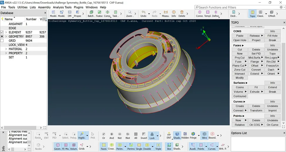
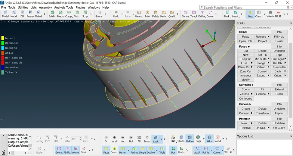
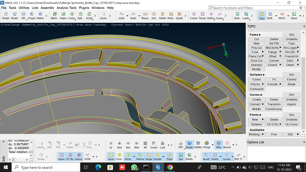
we use << FEATURE>> as there are multiple regions to select. Feature area command gives a single click selection of our region of interest. Thus reduces region selection time.<< FACE>OFSET > FEATURE AREA AT 40 DEGREES (IT WILL ONLY SELECT THAT AREA WHOSE ANGLE IS LESS THAN 40 DEGREES) >> and also use the < MIDDLE > option command selecting known surface on both said click the middle mouse button to generate mid surface
4) Set New PID To MID
Here we set new PIDs to different components and refined the geometry to better
Understand it's a feature.
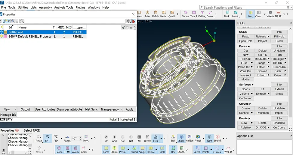
5) Checking Mid Surface Geometry
· Check the geometry again for mid-surface. the bottle cap has passed the check
· Hear we switch off the triple cone because when we take mid for the plastic component two or more surface edges are joined
6) Sizing Perimeter, Defeaturing & Mesh Preparations:
Change all perimeter element distances according to quality parameter Confirm whether perimeter element distances are in an acceptable range Here in the latch hole, some elements have un uniform distance between the perimeter element By removing unnecessary HOT POINT and again resizing perimeter elements' distance we can bring distance to an acceptable range Here region is too small & it might fail in the minimum length criteria so we have to DEFEATURE it.
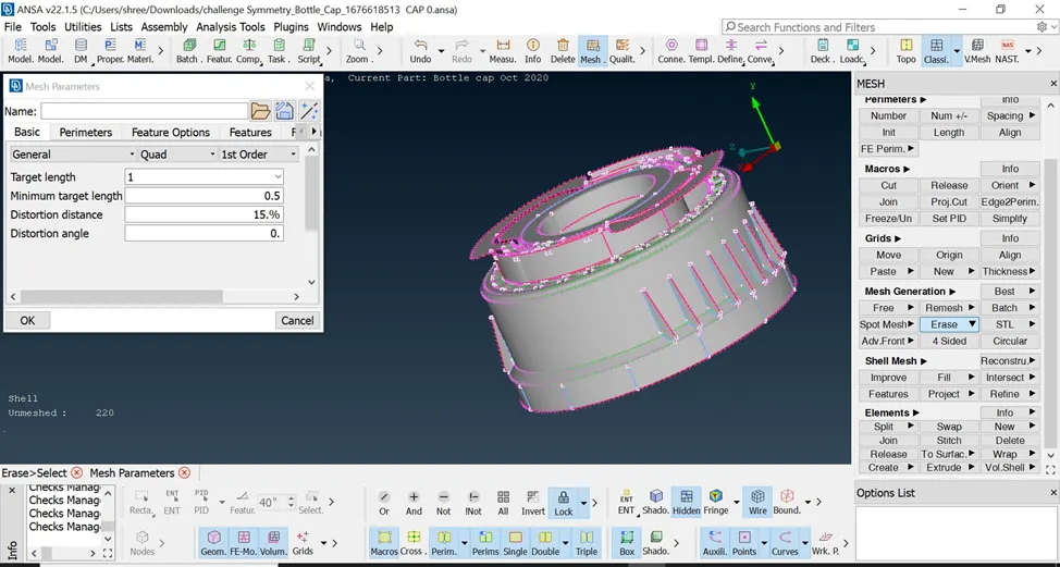
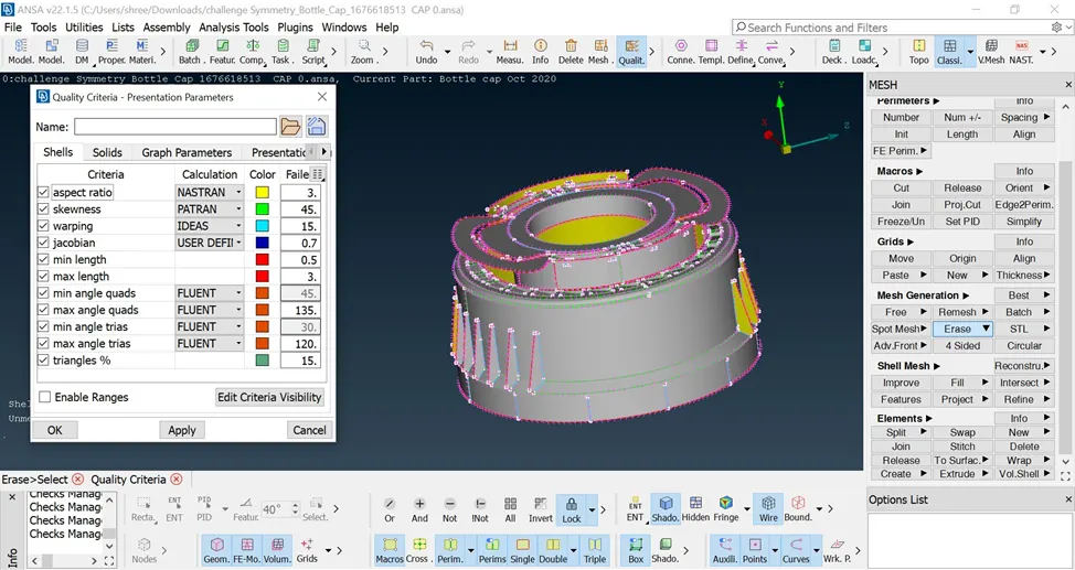
7) Defining Quality Criteria & Meshing Parameters
Input all the given QUALITY PARAMETERS
8) Meshing
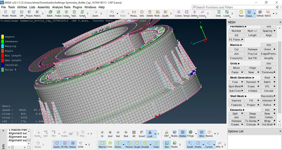
Definition - A mesh is a network that is formed of cells & points. It can have almost any shape in any size & is used to solve partial differential equations Each cell of the mesh represents an individual solution of the equation which, when combined for the whole network results in a solution for the entire mesh. For good mesh quality divide the domain into appropriate sections by using<< CUT>>.
To apply mesh use << BEST>> and to remove the mesh use<< ERASE>>.
Clear the mesh quality by the combination of
<< RECONSTRUCT>> (for automatic alternate mesh suggestions/pattern smoothing effect ), << SPLIT>> (to remove the tria and manipulate them ),<< MV>>(to adjust the element within the surface ), << CUT>> (Defining the region to mesh )
Rules for mind :
- Trias should be less but should be kept where it is necessary
- Trias should always move/point toward diverging sections
- The rotational pattern should be avoided
- Uniform perimeter element number should be ensured before meshing
- Unnecessary hot points should be removed
- Feature area and fillet region should be given more care
- Element should not fail in any quality criteria
Learning outcomes :
At the end of this challenge, I can able to perform geometry clean-up for any complex plastic component
Generate midsurface / skin for any complex plastic component.
Generate the shell mesh meeting the given quality criteria for any complex plastic component
Identify the quality failure and resolve the failure & improve the mesh quality
Working with ANSA
Conclusion:
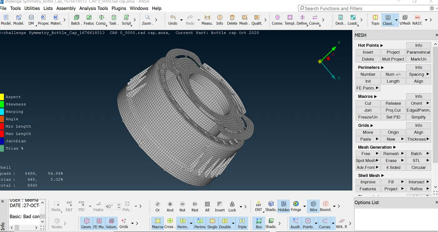
Hence midsurfacing / meshing / and assigning thickness is done successfully To conclude