Project 2 - 2D meshing on the instrumental Panel
CHALLENGE WEEK 7
For the given component, check for the geometrical errors and mesh with the given element Quality criteria. After meshing the component the thickness has to be assigned.
Write a detailed report on your meshing process and also mention which method you used to extract the mid-surface along with the reason.
|
S.No |
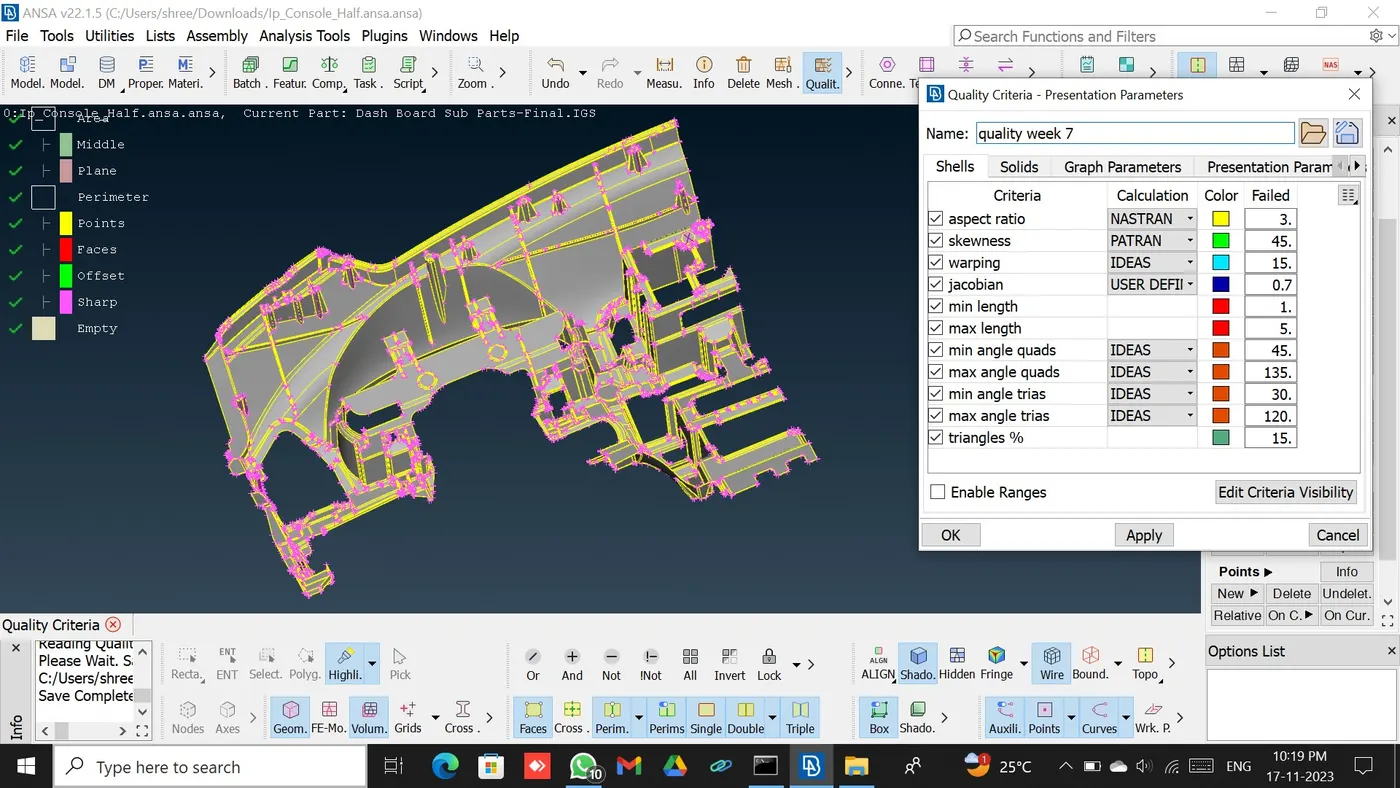
Quality Criteria |
Value |
|
1 |
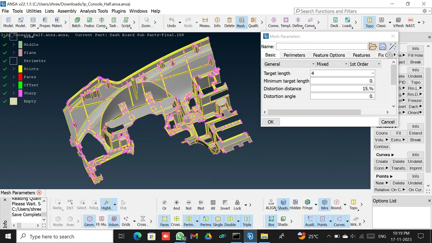
Target/Average length |
4 |
|
2 |
Minimum Length |
2 |
|
3 |
Maximum Length |
6 |
|
4 |
Aspect |
3 |
|
5 |
Warpage |
15 |
|
6 |
Skewness |
45 |
|
7 |
Jacobian |
0.7 |
|
8 |
Minimum Quad Angle |
45 |
|
9 |
Maximum Quad Angle |
135 |
|
10 |
Minimum Tria Angle |
30 |
|
11 |
Maximum Tria Angle |
120 |
|
12 |
Tria Percentage |
15 |
Aim: For the given component, check for the geometrical errors and mesh with the given element Quality criteria. After meshing the component the thickness has to be assigned
Given data:
|
S.No |
Quality Criteria |
Value |
|
1 |
Target/Average length |
4 |
|
2 |
Minimum Length |
2 |
|
3 |
Maximum Length |
6 |
|
4 |
Aspect |
3 |
|
5 |
Warpage |
15 |
|
6 |
Skewness |
45 |
|
7 |
Jacobian |
0.7 |
|
8 |
Minimum Quad Angle |
45 |
|
9 |
Maximum Quad Angle |
135 |
|
10 |
Minimum Tria Angle |
30 |
|
11 |
Maximum Tria Angle |
120 |
|
12 |
Tria Percentage |
15 |
Given component
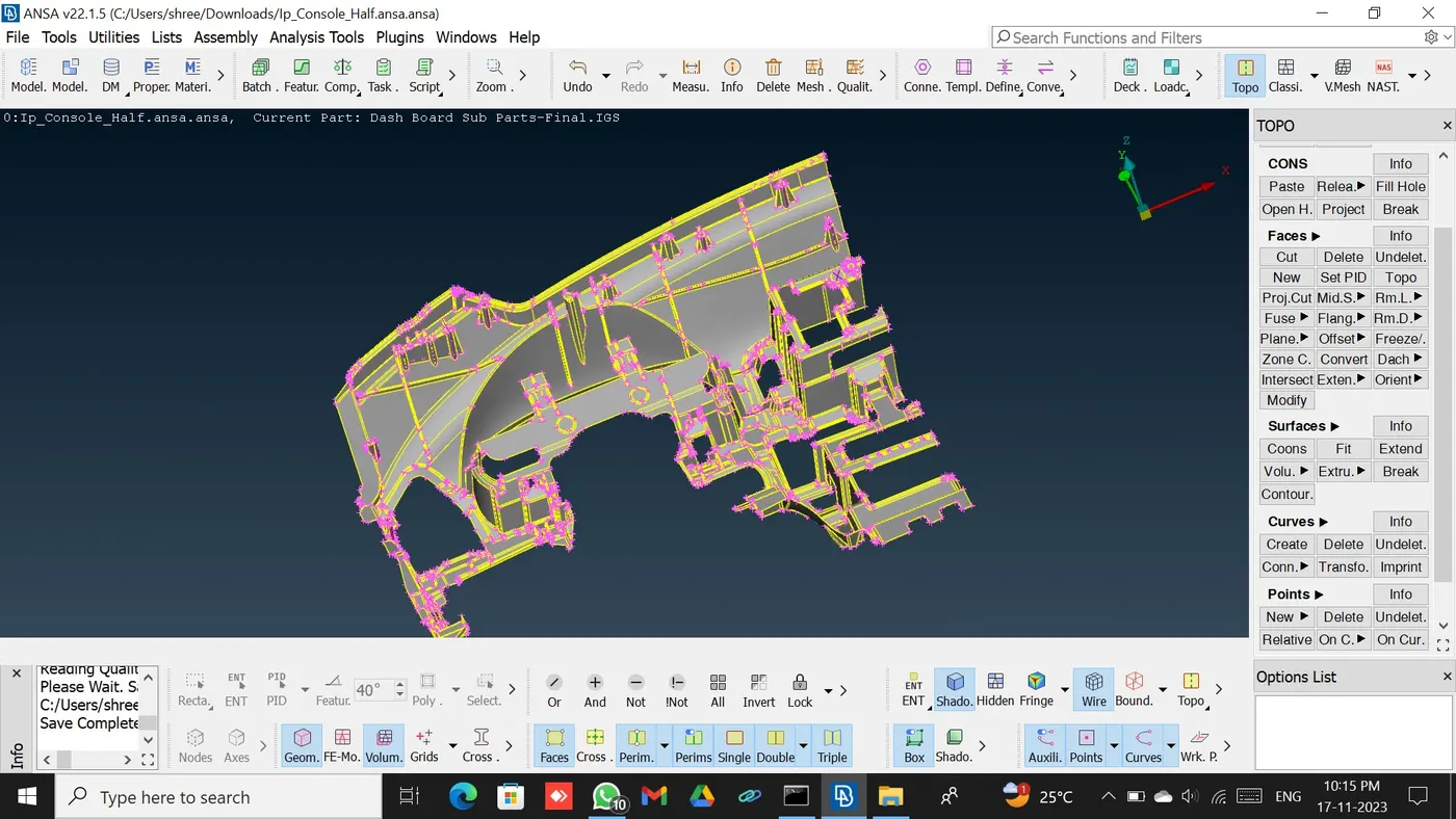
Process step for a given particular component
1. Check the geometry of the component
2. Putting the given data of quality criteria and mesh model
3. Choosing the best option for mid-surface generating
4. Generating mesh for mid surface
5. Avoid the maximum off element
6. Smooth the mesh element
Step 1: Check the geometry of the component
Tools>Checks>Geometry function. The Check Geometry window appears and the user can select to check for the following geometrical problems
Unchecked faces: faces that failed the shadow operation. (Automatic Location and isolation of the Topological problems) Needle
Faces: or degenerated faces are faces that have their opposite CONS coincident. Dealing with triple or more CONS)
Collapsed Cons: A CON where its starting and ending positions coincide.
Triple Cons: Areas where three or more faces have a common boundary Overlaps: Overlapping faces
Cracks: Red CONS at inner areas (holes are excluded).
Single Bounds: Red CONs at outer areas. Holes (included) In the Checks window all problems are reported with red color. Under the Description column, the kind of problem is explained. Focus functions are available in order to isolate geometrical problems and handle them more easily. Select to fix all or specific reported problems by pressing the right mouse button on the header of the list or one or more highlighted problems.
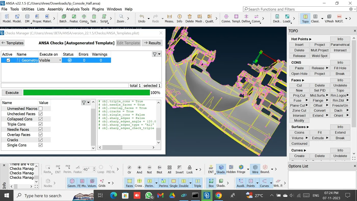
! Note: All problems except triple CONs can be fixed by automatic fixing.
! Note: Right mouse clicking on Check Geometry line, performs an action to all listed problems. In the case where not all problems are fixed automatically, retry or proceed to fix them manually
Step 2: Putting the given data of quality criteria and mesh model
ANSA provides shell mesh quality checks of the generated Geometry Mesh or of imported FE-Model elements. The user may select the definition type and threshold value of each quality criterion and the criteria to be active for each quality check.
Step 3: Choosing the best option for mid-surface extraction
There are many methods for mid-surface extraction
· The OFFSET function In order to relocate the Faces to the “middle surface”, the FACES option of the OFFSET function may be used.
· Skin function turns the solid description of a thin part into a thin shell description by isolating the outer or inner skin of the solid description.
· CASTING function. Automatic Middle surface Mesh generation. The MID.SURF.
· Middle option
The MID.SURF.CASTING function
For all models, even for the most complicated with a lot of ribs and thickness variation, there is the capability to move a step forward and generate FE surface mesh in the middle position of the model. Some of the advantages are:
1. Fully automated process
2. Function can be applied by specifying only a minimum thickness value
3. Although it is recommended to use the function on clean geometry, it can be used in geometry with problems as well
4. Generated surface mesh ID of very good quality with user-specified target element length and type
5. Thickness value is automatically applied to each element
6. Time needed to improve areas is much less than to extract the middle surface and fix it manually
! Note: tooltips are available on all options. They become visible by hovering the cursor on the field description area
Here we using the casting function because the given components are so complicated to extract mid-surface for other function
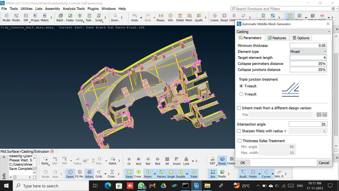
Parameters
Minimum thickness: minimum thickness value that appears on the model.
Element type: controls the type of the elements to be generated.
Target element length: target element length value. It cannot be lower than the minimum thickness.
Collapse perimeters distance: distance under which perimeters will collapse It can be given as an absolute value or as a percentage of the Target element length.
Collapse junctions distance: distance under which junctions will collapse. It can be given as an absolute value or as a percentage of the Target element length.
Triple junction treatment: select how casting will treat Triple junctions.
Inherit mesh from a different design version. Casting will use an already existing mesh from a different design version of the part and create new elements only in the modified area
Step 4: Generating mesh for mid-surface
Here we use the casting function that automatically gives both mid-surfaces along with mesh generation so no need to generate mesh for mid-surface
Working With Align Manager
Sometimes the mesh quality is generated by MID. SURF CASTING function is not the desired one and manual treatment is needed in order to improve the problematic areas. The Align Manager is a powerful tool for fixing these areas. This tool enables the user to auto-align shells to the correct middle position and also auto-assign the proper nodal thickness.
Creating Align Entities To invoke the Align Manager use the Faces>Mid.Surf>Align Manager option. Automatically the ‘color mode’ changes to ’Align’ and we are able to distinguish the Align entities each one shown with a different color. A list with the Align entities is shown in the Align Manager window. The Align entities are FE areas that are assigned to specific geometrical faces and they lie exactly on their middle surface.
! Note: the context menu also pops up if you continuously right-click on the screen while the Align Manager is open.
If the Areas option is selected on the Align Manager window you can select shell Align entities by picking them from the screen. Then, automatically the Faces that the Align entity is assigned to are shown with light blue colour and this Align entity is highlighted in the list. There are different types of Align entities. Plane when the entities lie on a specific Plane. The plane can be described as the middle plane of 2 faces, or via point selection. Plane entities are shown with red color. To define a new Plane entity click on the Align Manager window, select the New-Plane option, and the following window pops up. You have the option between selecting Align entities (entities that are auto-recognized by the casting algorithm) or shells (elements that were manually created AFTER the casting algorithm was executed and in “Align” color mode appear with grey color).
! Note: If you have already picked Align entities, the New option will not ask you again to select Align entities and the window above will be skipped.
Pick the entities you want to Align and press Next. If the geometry visibility is on, geometry automatically pops up. Define the new plane with a 2-3 point selection or by selecting 2 faces. Press Finish to Align the entities on the desired plane.
Middle
When the entities lie on a specific curved surface. Middle entities are shown with green color. To define a new Middle entity right-click on the Align Manager window, select the New-Middle option, and select the Align entities/Shells to Align. Select the First group of faces. Press Next or confirm with the middle mouse click. Select the second group of faces. Press Next or confirm with middle mouse click. Press finish or confirm with the middle mouse click. The entities are auto-aligned to the exact middle of the selected groups of faces
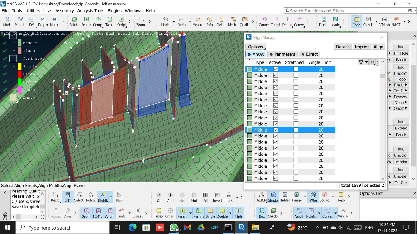
Offset
When the entities lie on a surface offset by one or more faces. Offset entities are shown with blue color. To define a new Offset entity right-click on the Align Manager window, select the New-Offset option, and select the Align entities/Shells you want to Align. Then select the faces that are going to be offset.
The offset distance can be picked from the screen with the options to select thickness (were half of the selected distance will be used) or half-thickness (where the whole of the selected distance will be used). Distance can also be inserted manually Press finish to auto-align and the entities on the desired position
Perimeters
When element edges lie exactly on a perimeter which can be defined by faces, points, or be a projection of a CONS. Perimeters can be found on the Perimeters tab of the Align Manager window. Perimeter entities are colored according to their type.
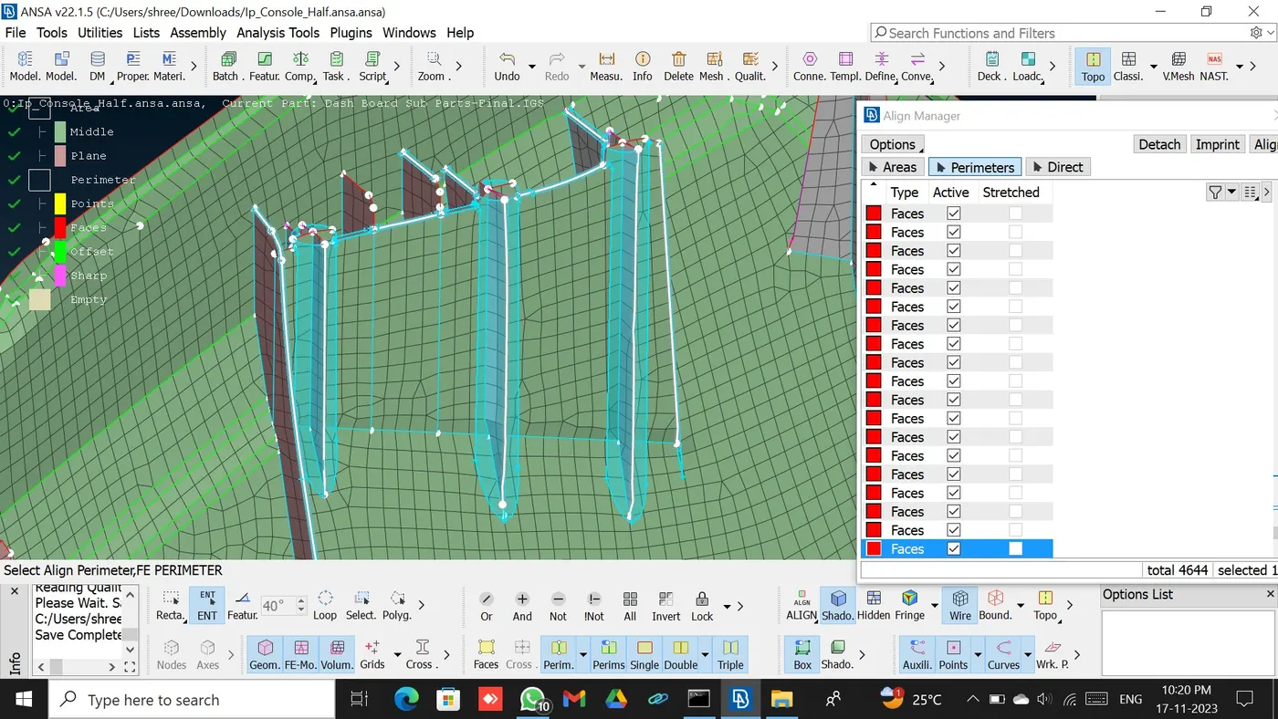
Faces
When the element edges lie exactly on one or more faces. After the casting tool runs, all single bounds are automatically assigned to their boundary Faces. Faces type perimeters are shown with red color.
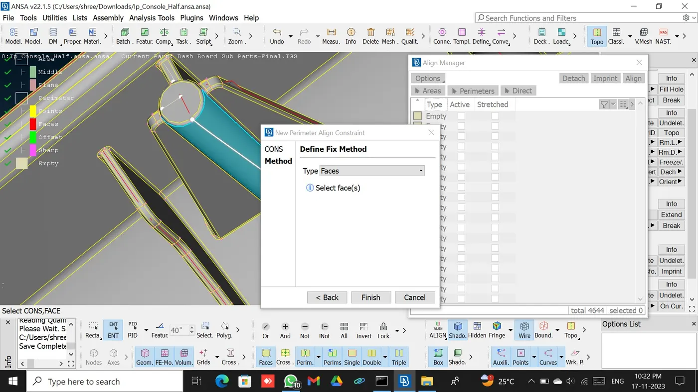
Offset
When the perimeter is a projection of one or more CONS. Offset-type perimeters are shown with green color.
Imprint
Imprint function projects CONS from the geometry to the middle surface FE. With this functionality, any geometrical CONS can be easily transferred to the FE model. Imprint creates perimeters of type Offset.
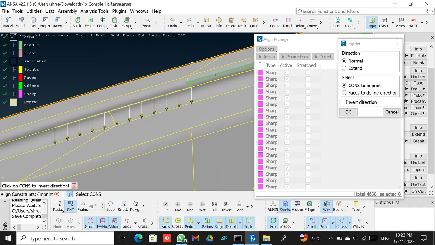
! Note: The imprint method can also be used to an already existing perimeter for alignment!
Step 5: Avoid the maximum off element
· Any off elements in the surface mesh will lead to bad elements in the volume mesh. Fix them prior to volume meshing.
· First, ensure that the surface mesh is of good quality. Switch to HIDDEN mode to see if there are any OFF elements.
· The Reconstruct option Reconstruction is a powerful tool for the creation of a high-quality surface mesh. It is applied on an existing mesh and performs re-meshing, in order to correct problematic areas and optimize the overall quality and flow of the mesh. For Geometry Mesh all modifications are made maintaining the mesh on the underlying CAD surface.
· Using the split option to maintain minimum the off elements
Reconstruct Mesh
Reconstruction is a powerful algorithm for the creation of a high-quality surface mesh. It is applied on an existing mesh and performs re-meshing to:
- optimize the overall quality and flow of the mesh (reducing the number of trials of mixed mesh
- Correct quality criteria violations
- enforce special mesh treatment of holes, flanges, and fillets
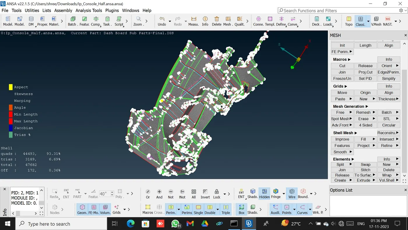
· The function can be applied on Macro Area mesh and/or FE-model mesh Reconstruct also has embedded the Fix Quality functionality, so any problems that cannot be fixed by re-meshing, are automatically fixed by nodal movements. Before using the Reconstruct function, the user should set appropriate values in the Quality Criteria and Mesh Parameters windows
· ANSA reconstructs the mesh and provides a preview of the result.
· The Preview window opens, and the user can: Invert: switch between the Old and New mesh, or overlay both by activating both flags
· Perimeters: flag to draw or not perimeters
· Rerun: perform another reconstruction step, in order to further improve the previewed result
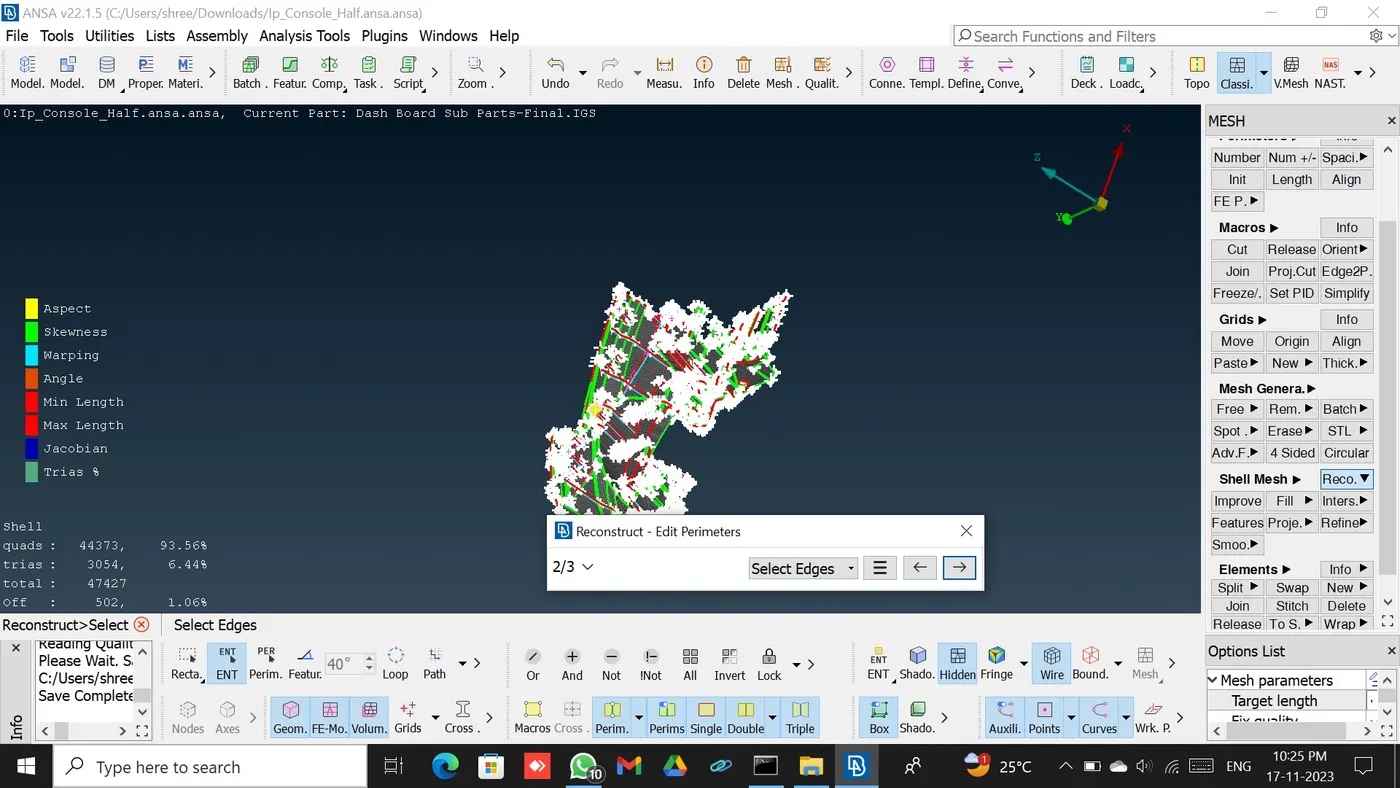
· Finish: accept the previewed result. Using Reconstruct on the whole Part, improves the overall quality of the mesh, with all the bad areas fixed, and the triangle percentage reduced.
· Reconstruct has also changed the number of some Perimeter Nodes, in order to align better a quad mesh. Some problems that were caused there, by narrow Macros, were overcome by nodal movements.
· For optimum results and automatic Perimeter Join regarding mesh improvement, The Reconstruct function can also be used on selected Macro Areas or elements of Macro Areas.
Learning Outcomes
· Includes this challenge I learnt how to extract the mid surface for a particular CAD component
· We can decide which type mid surface extracting with the given type of component along with time
· Learnt how to take mesh for child surface with type of mesh generation
· We can compare the particular mid-surface and mesh model to choose the best method
Conclusion
Given three cases casting is the best option over skinning because it saves time and generates mesh flow only for this type of component
LINK
DATABASE
https://drive.google.com/file/d/1AJXeuJ3XrPFMbIrQHRDMX16GUV-2iyzi/view?usp=drive_link
https://drive.google.com/file/d/1SHruNV_ZJgO41t16Q1-A54o-x303aufs/view?usp=drive_link