Week- 6 - Solid meshing
week 9 Solid Meshing
Aim For the given Rear view mirror component, check for the geometrical errors and mesh the Surfaces with the given 2D element Quality criteria given
Given Data
S.No | Quality Criteria | Value |
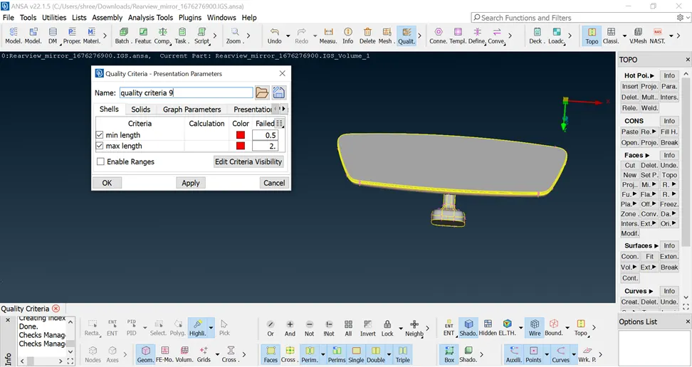
1 | Target/Average length | 1 |
2 | Minimum Length | 0.5 |
3 | Maximum Length | 2 |
Use tetra elements to mesh the Volumes defined in the model and check for the below quality after Volume meshing.
| S.No | Quality Criteria | Value |
| 1 | Tet collapse | 0.2 |
Given component: Rear view mirror component
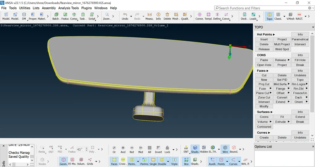
About rearview mirror
A rearview mirror in an automobile is a flat mirror designed to allow the driver to see behind the vehicle through the rear window (rear windshield). It is usually affixed to the top of the windshield on a double-swivel mount, allowing it to be adjusted to suit the height and viewing angle of any driver. In case of a collision, it can swing harmlessly out of the way if impacted by a vehicle occupant.
Process step for a given particular component
1. Check the geometry of the component
2. Putting the given data of quality criteria and mesh model
3. batch mesh generation
4. Generating volume mesh for solid component
5. Avoid the off element and collapse element
Step 1: Check the geometry of the component
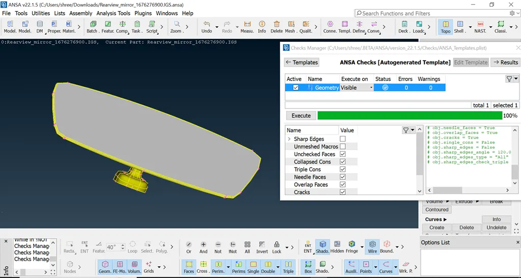
Tools>Checks>Geometry function. The Check Geometry window appears and the user can select to check for the following geometrical problems
Unchecked faces: faces that failed the shadow operation. (Automatic Location and isolation of the Topological problems) Needle
Faces: or degenerated faces are faces that have their opposite CONS coincident. Dealing with triple or more CONS)
Collapsed Cons: A CON where its starting and ending positions coincide.
Triple Cons: Areas where three or more faces have a common boundary Overlaps: Overlapping faces
Cracks: Red CONS at inner areas (holes are excluded).
Single Bounds: Red CONs at outer areas. Holes (included) In the Checks window all problems are reported with red color. Under the Description column, the kind of problem is explained. Focus functions are available in order to isolate geometrical problems and handle them more easily. Select to fix all or specific reported problems by pressing the right mouse button on the header of the list or one or more highlighted problems.
Step 2: Putting the given data of quality criteria and mesh model
ANSA provides shell mesh quality checks of the generated Geometry Mesh or of imported FE-model elements. The user may select the definition type and threshold value of each quality criterion and the criteria to be active for each quality check.
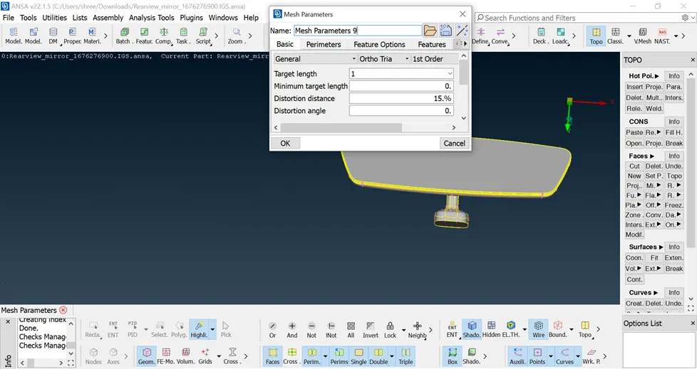
Mesh Parameters: According to the selected analysis -mesh type (Crash, NVH, Durability, Cfd, Structural Tria) different features are activated. For example, when the Structural Tria is selected, the Flanges treatment is by default active while for the Crash case the Flanges treatment is inactivated. Of course, it is suggested to the user to inspect the default values and make any modifications to meet all his requirements.
Properties
The Properties tab displays all the properties associated with the selected Parts/Groups. In cases such as tailor-blank Parts that have more than one property, the user can quickly see this information in the Properties tab. Moreover, the columns displayed in this tab are in sync with the columns in the Properties list of the whole model.
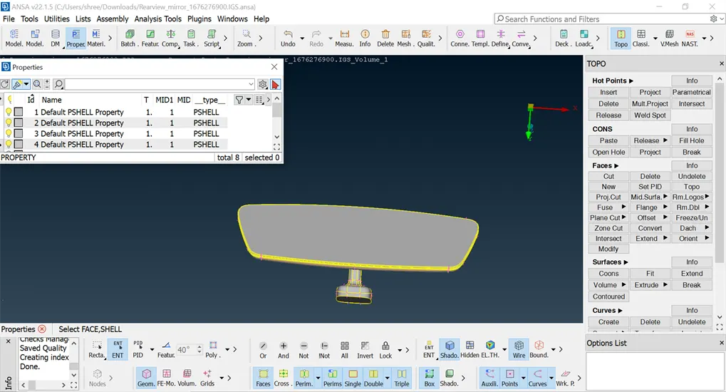
step 3: Batch Meshing
The Mesh Generation>Batch is an advanced function for generating Mesh on Macros. It applies the functionality of the BATCH MESH tool on selected or visible Macros taking into account the global Mesh Parameters and the global Quality Criteria.
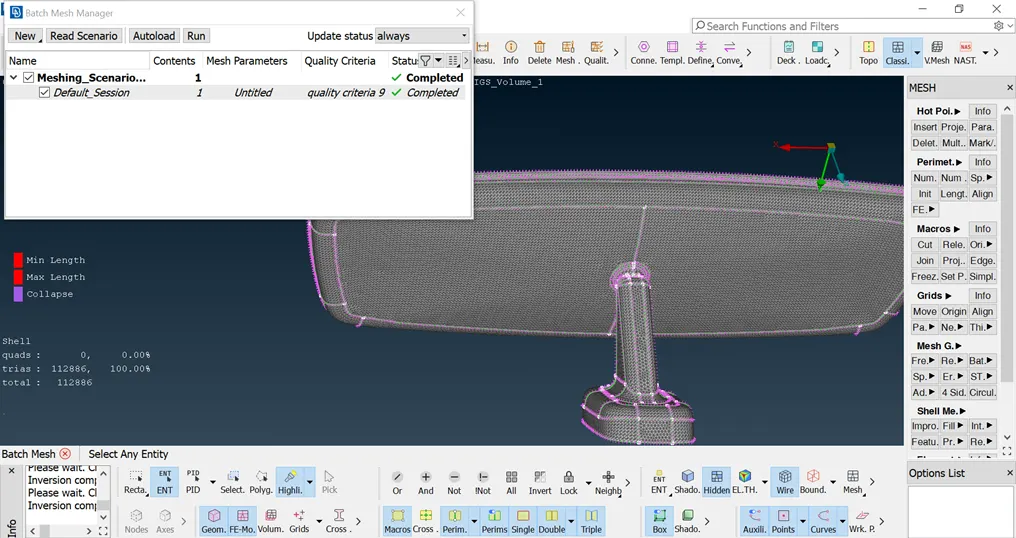
Quick Start
the necessary steps that are needed to set up and run a Batch Meshing Scenario for one or more parts. To run any Batch Meshing procedure the following steps are needed:
1) Open Batch Mesh Manager and create a New meshing scenario
2) Assign entities to be meshed
3) Input/Load the Mesh Parameters
4) Input/Load the Quality Criteria
5) Run Batch Mesh
6) View Statistics
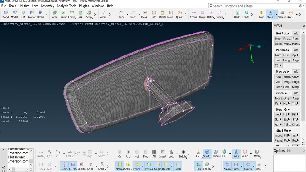
step 4:volume mesh
All the functionality available for the handling and creation of solid elements is located under the MESH> VOLUME and under the separate Volume Mesh module.
By activating the Create volume mesh flag in the Volume Mesh tab the user can activate the generation of volume mesh after the successful completion of shell meshing. ANSA Batch Mesher is capable of creating volume mesh on parts that contain already defined volumes. For a detailed description of the volume mesh parameters please refer to Chapter
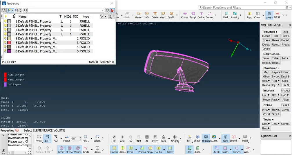
Unstructured Mesh
The available mesh generation algorithms are found under V.Mesh> Unstructured Mesh or at the MESH>Volumes> Mesh Vol. These algorithms are: -
Tetra Rapid: tetrahedral mesh (with pyramid elements if the starting surface mesh contains quad elements).
Tetra FEM: tetrahedral mesh (with pyramid elements if the starting surface mesh contains quad elements) mainly for structural applications.
Hexa Interior: a combination of hexa or penta layers all around the surface mesh, Cartesian hexahedral mesh with variable size inside the main volume, and a combination of tetra and pyramid elements in between.
Hexa Poly: a combination of pyramids or tetras all around the surface mesh, Cartesian hexahedral mesh with variable size inside the main volume, and a combination of polyhedral and tetra elements in between.
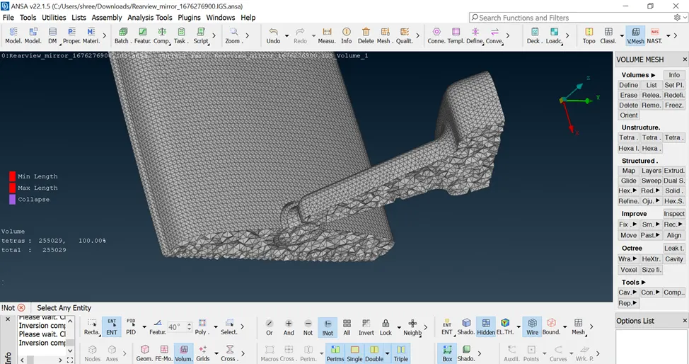
Step 5: Avoid the off element and collapse element
· Any off elements in the surface mesh will lead to bad elements in the volume mesh. Fix them prior to volume meshing.
· First, ensure that the surface mesh is of good quality. Switch to HIDDEN mode to see if there are any OFF elements.
· The Reconstruct option Reconstruction is a powerful tool for the creation of a high-quality surface mesh. It is applied on an existing mesh and performs re-meshing, in order to correct problematic areas and optimize the overall quality and flow of the mesh. For Geometry Mesh all modifications are made maintaining the mesh on the underlying CAD surface.
· Using the split option to maintain minimum the off elements
conclusion
For the solid component, I'm following the above process steps for the best mesh generation for both batch meshing and volume meshing
link
radian
https://drive.google.com/file/d/1Xn4Lf8vNDg4Djt0Fyc_shgbTRjz8wevb/view?usp=drive_link
Fem
https://drive.google.com/file/d/1DO0bCBeeu6a1hcCtpBxFKbhyFeIQGhwQ/view?usp=drive_link
IGS
https://drive.google.com/file/d/1E0_E7D7BqVHac3KnQzphgrvDWJDi8cmZ/view?usp=drive_link