Week 4- Meshing of Backdoor Challenge
Aim: To mesh the backdoor geometry of a car and assign thickness.
Given model:
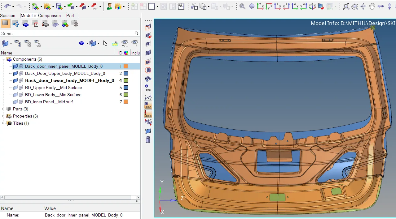
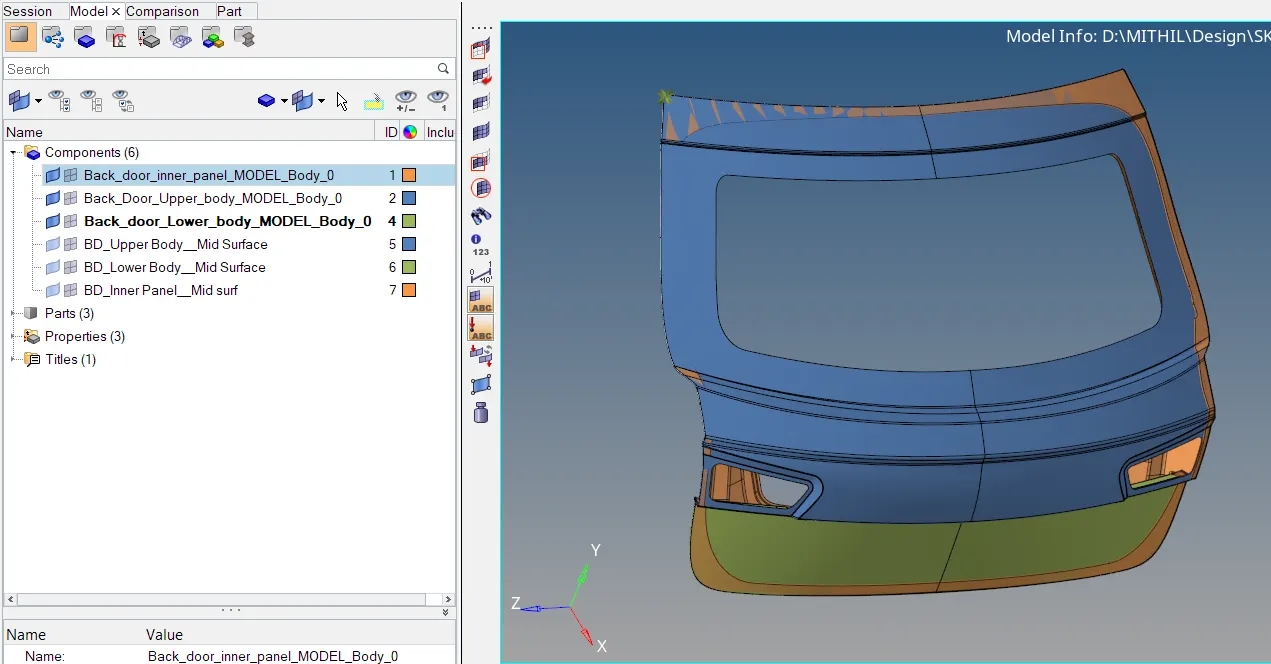
Objective:
1. Geometrically clean the model and making sure no deformities of surface are present.
2. Extracting the mid-surface of the model and clean it to avoid any errors.
3. Generating mesh on mid-surface using mixed element criteria.
4. Carry out the quality check of the generated elements.
5. Provide thickness to mesh as per part.
Note: In this Back door model 3 different components are provided i.e.:
a. Back Door Inner Panel.
b. Back Door Upper Body.
c. Back Door Lower Body.
All the 3 components are separated and meshed respectively. Below procedure is for (a. Inner Panel) and other two components are also meshed following same steps.
A. Procedure for Meshing of Inner Panel:
1. First of all geometric clean the model after we import it, since there might be some distortion or error in the model.
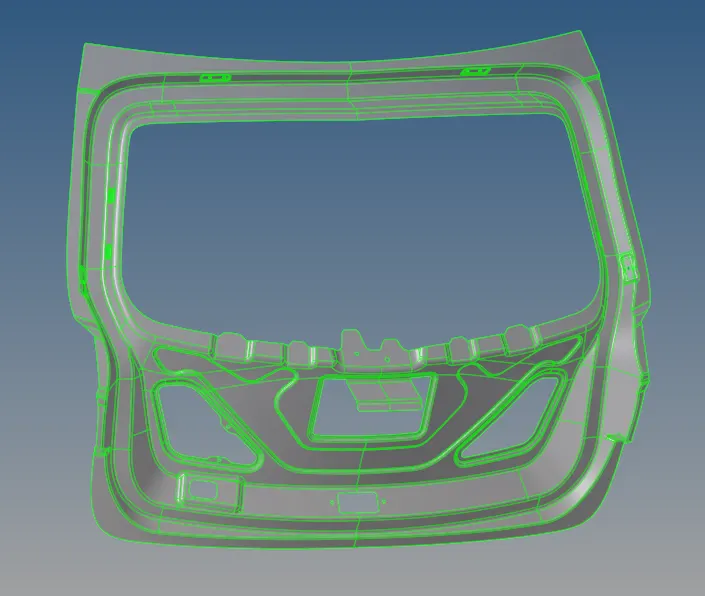
As shown below the Wire Frame View Mode shows no free edges after the geonetric cleanup of the compnent.
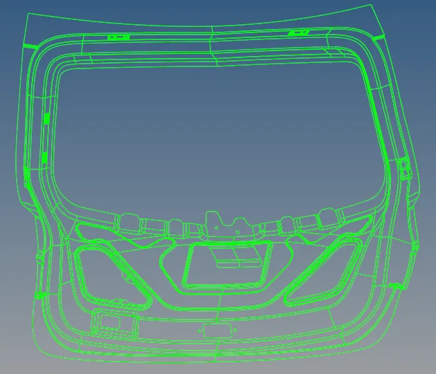
2. Next step is to extract mid-surface of the component. But first we need to check for the uniform thickness of the model to decide weather to proceed with sheet metal model method or plastic model method. As the thickness is uniform, we can extract mid-surface using skin off-set method. Now check for any deformation in mid-surface and do through geometric cleanup of the mid surface.
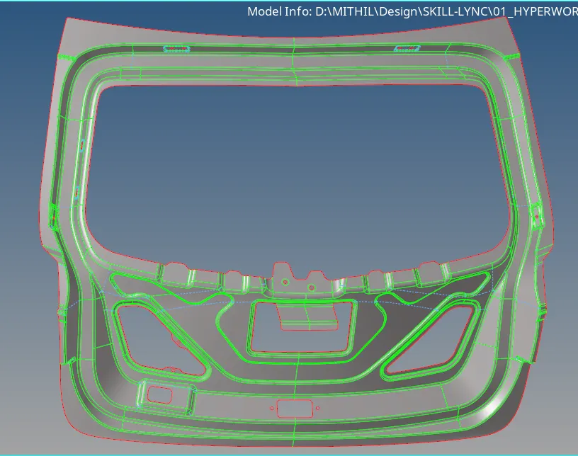
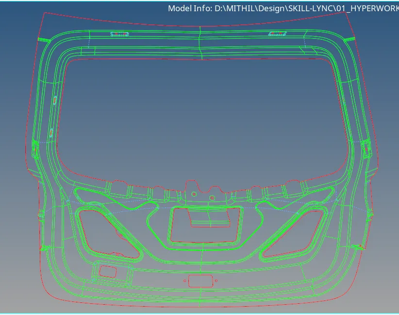
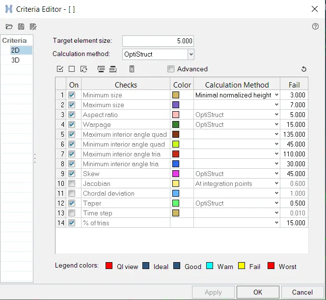
3. Now set the quality criteria for the meshing process as provided in the question, using Criteria file setting in Preference Tab.
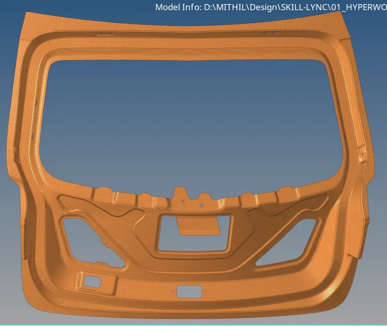
4. Now mesh the mid-surface using Auto-mesh command in 2D tab. In this change the element type mixed and element size to 5 mm, also ticked the Align & Size option for better mesh flow. For a better mesh flow try to mesh the mid-surface step by step instead of in one go. After meshing the component should look somewhat like this:
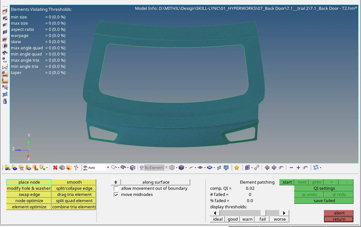
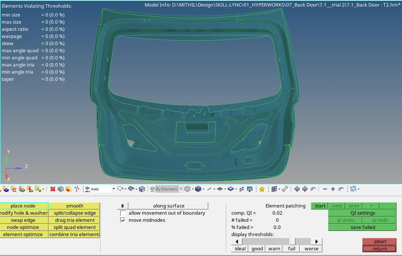
5. Next is to check for fail elements as per Quality criteria using Quality check command in 2D tab as shown below:
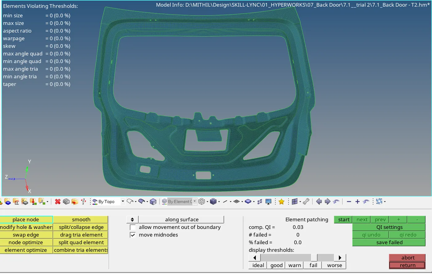
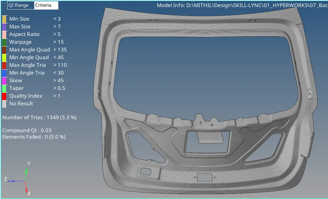
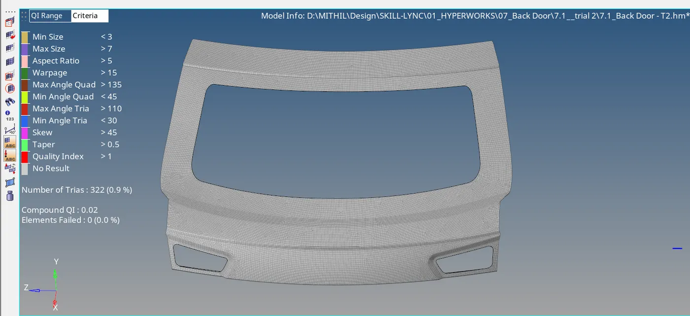
And also, by turning on Elemental Quality View as shown below:
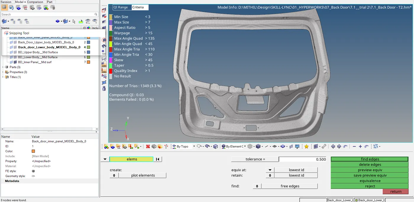
6. After meshing we need to check for the connectivity of the mesh element by using Equivalence command.
7. It is cleared that the component has cleared all the quality criteria, next is to provide thickness to it. To do that we need to create new property in the Property Tab and enter the thickness value 0.75 mm as per question and rename the property to Thk. — 0.75 mm as shown below:
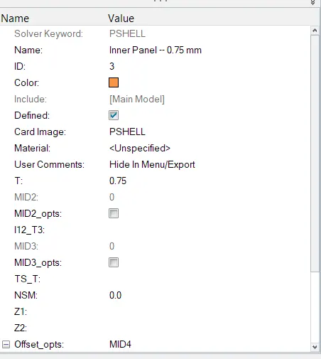
Now assign this property to the component for it to reflect onto the elements by right click the model and select assign option.
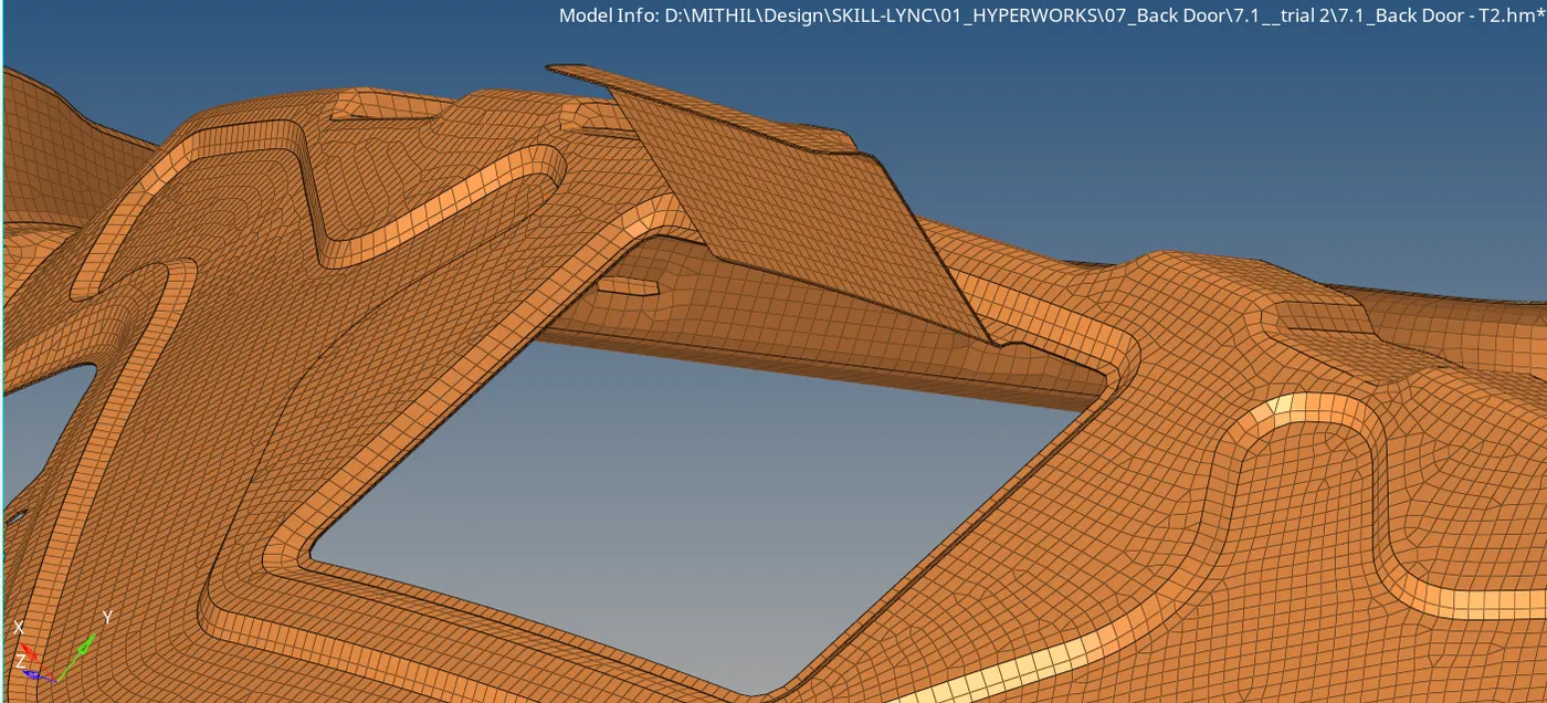
8. To view the 3D elements, change the view from: 2D Traditional Element Representation à 2D Traditional and Element Representation. Which will look something like this:
B. Procedure for Meshing of Upper Body:
· Upper Body is also meshed following the same procedure and the final result is shown below:
C. Procedure for Meshing of Lower Body:
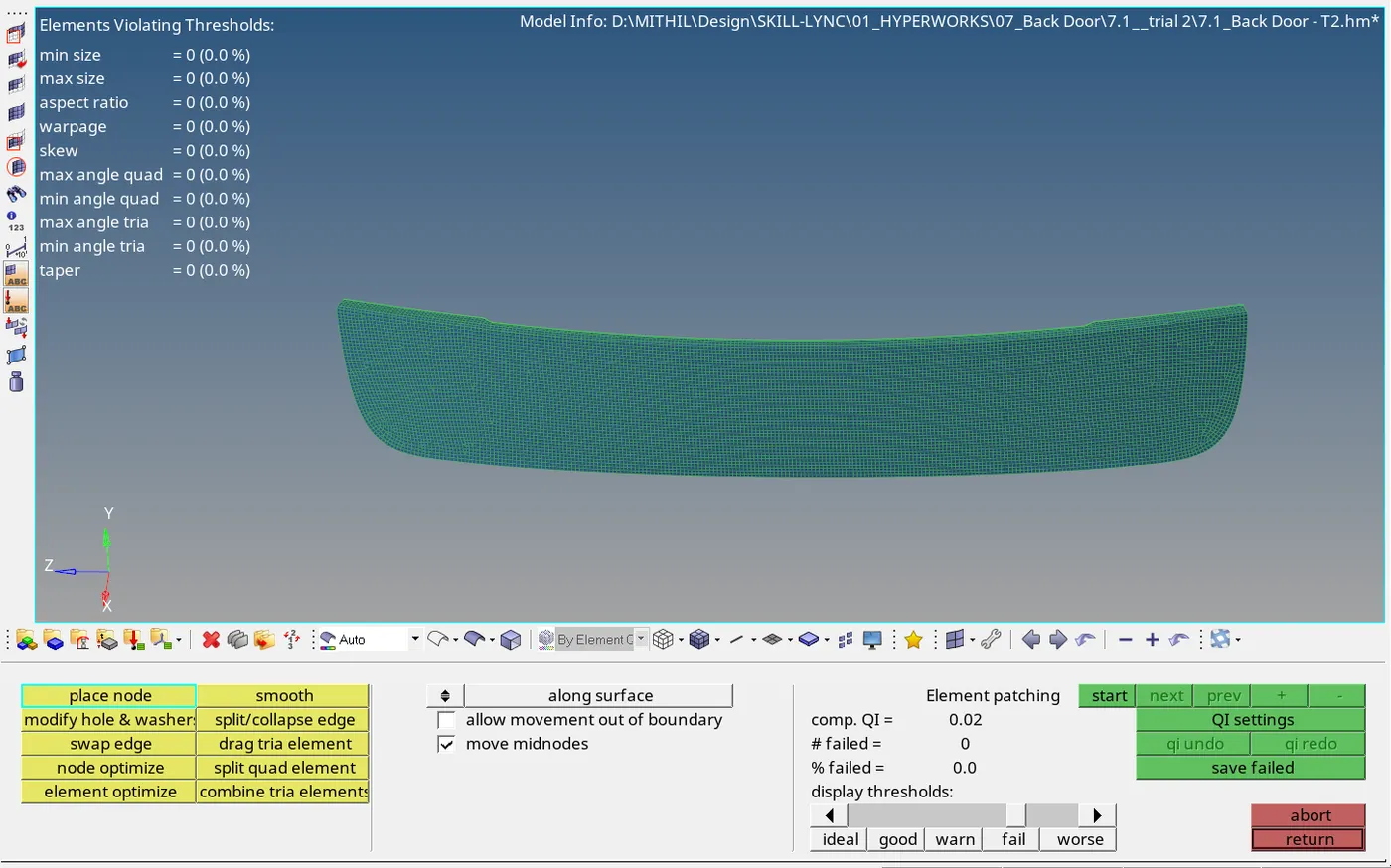
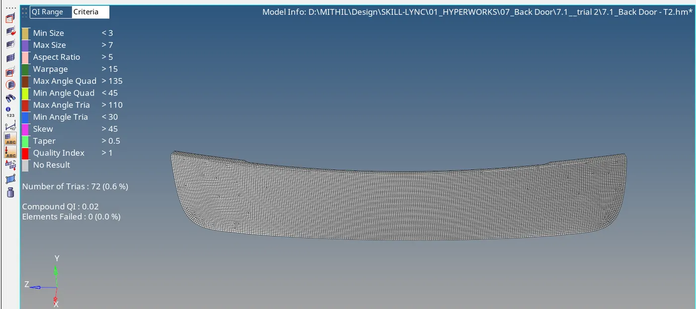
· Lower Body is also meshed following the same procedure and the final result is shown below:
v Final Meshed Assembly:
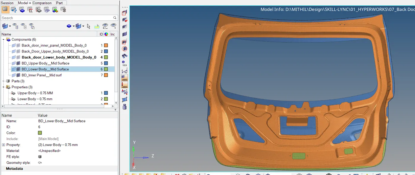
Conclusion: This project helps me to understand the methodology behind meshing of any large assembly components. How I should start with separating the components followed by geometric cleanup of the parts then generating mid-surface and provide 2d mesh to it, carry out Quality criteria and to generate final result by adding property to the component.
[ NOTE: AS THE MODEL FILE IS MORE THAN 20 MB, I HAVE ATTACHED LINKE OF THE MODEL AS TEXT FILE. ]