Week - 4 - Crash Box Simulation
Aim:
To simulate a crash test for a crash box for which mesh is given.
Assumptions and Informations:
1) Crashbox should be crash into a rigidwall
2) Material of crashbox is steel.
3) Thickness of crashbox is 1.2 mm
4) Initial velocity = 50kmph
Deliverables: 1) Input .k file and output files (D3PLOT, GLSTAT, SLEOUT, RCFORC)
2) Animation of the final simulation
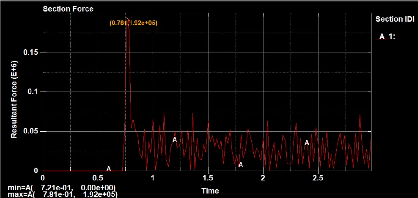
3) Cross -sectional forced generated in the middle of the crash box (along the length)
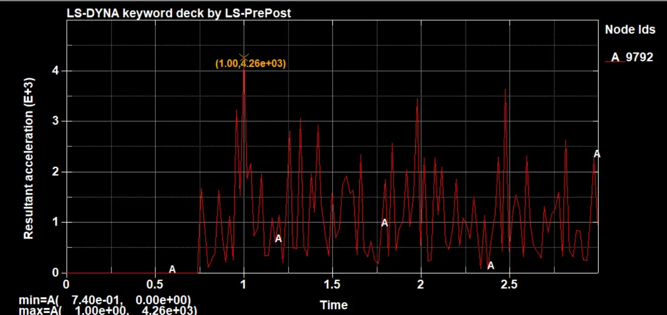
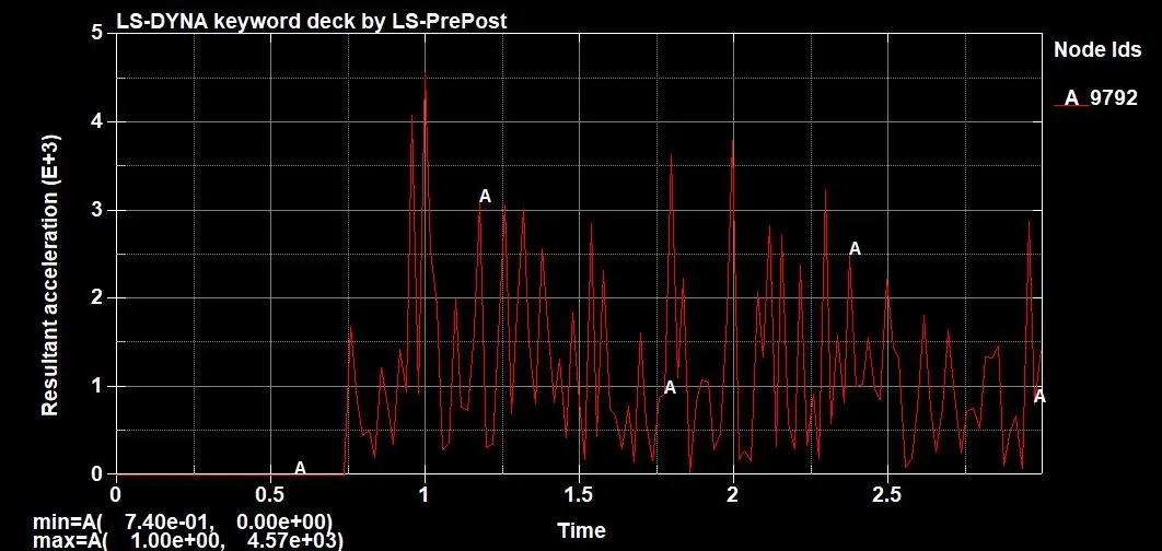
4) Acceleration plot of a node in the middle of the crash box (along its length)
5) Maximum directional stress and strain along the length of the crash box (X strain, Y strain etc.)
6) plot of all energies (total, internal, kinetic, hourglass, sliding)
7) compare the accelerations and stress/strain plots of 1.2/1.5 mm crash boxes.
Introduction:
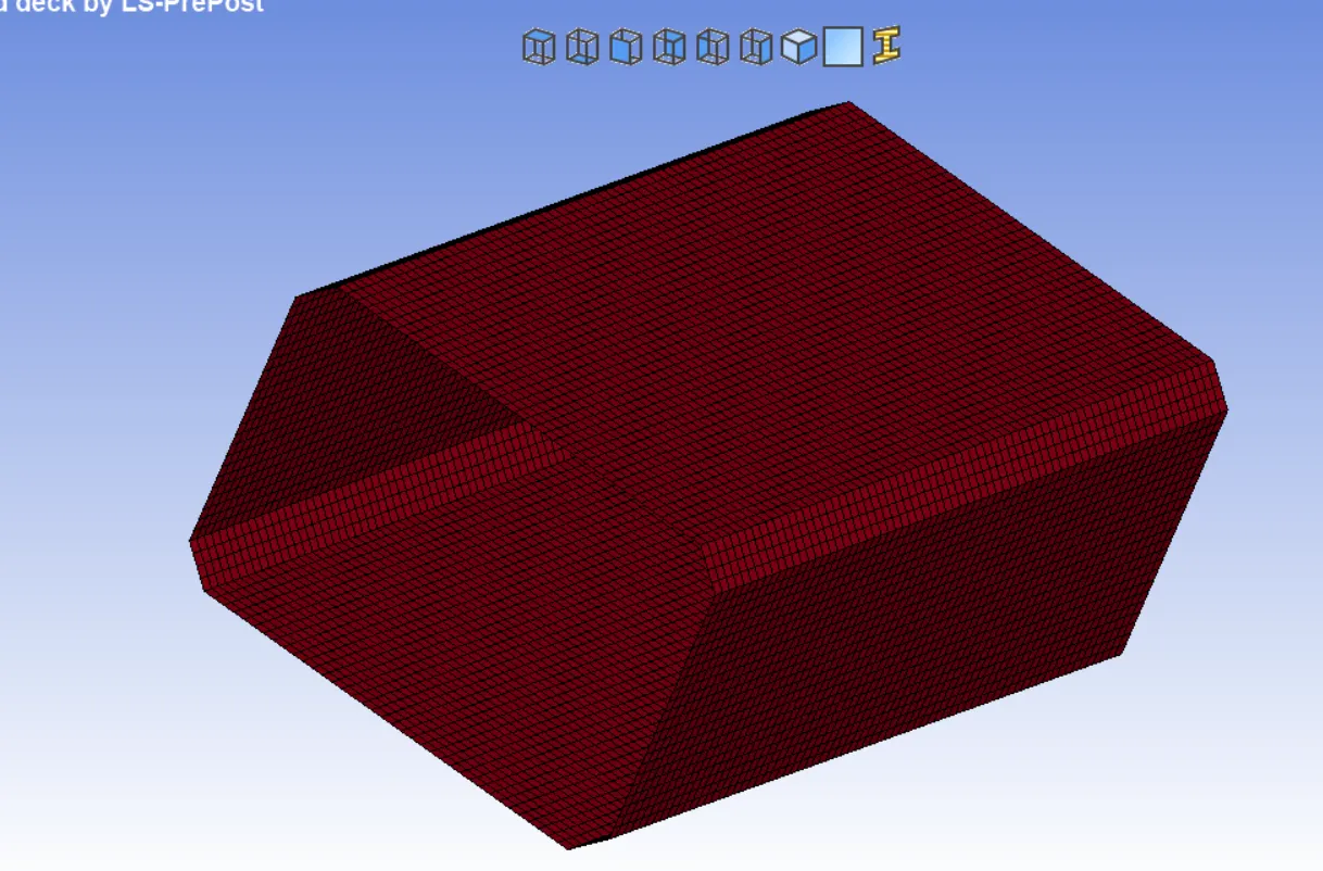
A crash box is a highly energy absorbing structure that crashes on application of loads and reduces impact on other components nearby. A full - fledges crashbox is a highly sophisticated design but in this case we will go with a rectangular channel which can thought of as the most simple crashbox.
Model Image:
Procedure:
1) Open the model in LS Pre-Post
go to file > open >> select given keyword file >> open
Mesh file will be open in LS Pre Post window.
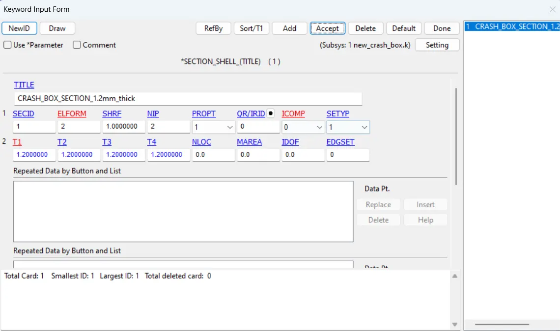
2) Add Section property
go to right pannel >> Model and Part >> Keyword manager >> all >> section >> shell >> give title = CRASH_BOX_SECTION_1.2mm_thick >> Thickness = 1.2 mm >> ELFORM = 2 >> Accept >> Done
3) Add Material
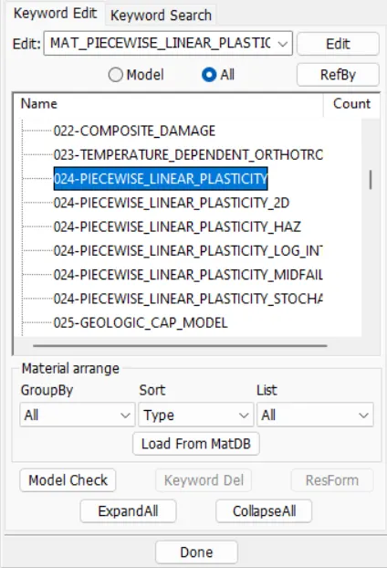
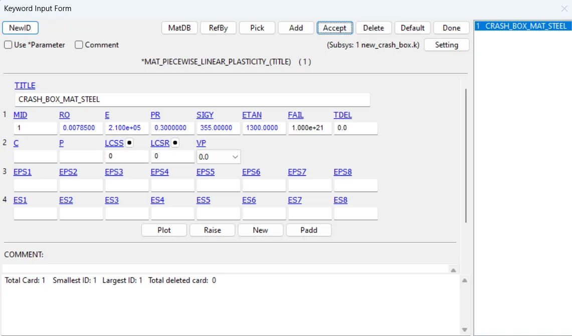
go to right pannel >> Model and Part >> Keyword manager >> all >> MAT >> 024_PIECEWISE_LINEAR_PLASTICITY >> Title = CRASH_BOX_MAT_STEEL >> Density = 7.853-3 >> E = 210e3 >> PR = 0.3 >> SIGY = 355 >> ETAN = 13e3 >> accept >> done
4) Hourglass (To avoid energy generation)
go to right pannel >> Model and Part >> Keyword manager >> all >> Hourglass >> Hourglass >> Title = HOURGLASS_ENERGY_CRASH_BOX >> IHQ = 2 >> Accept >> Done
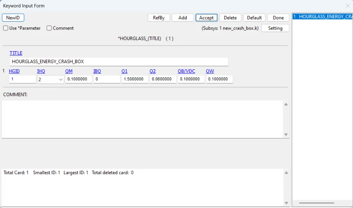
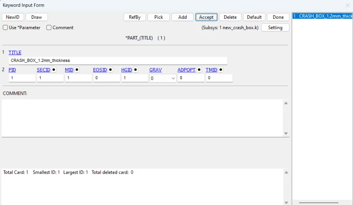
5) Assign Material, Shell and hourglass property to part
go to right pannel >> Model and Part >> Keyword manager >> model >> part >> part >> Title = CRASH_BOX_1.2mm_thickness >> Assign properties >> accept >> Done
6) Apply boundary Condition
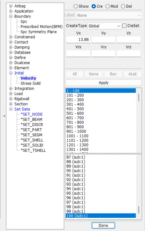
a) Initial Velocity
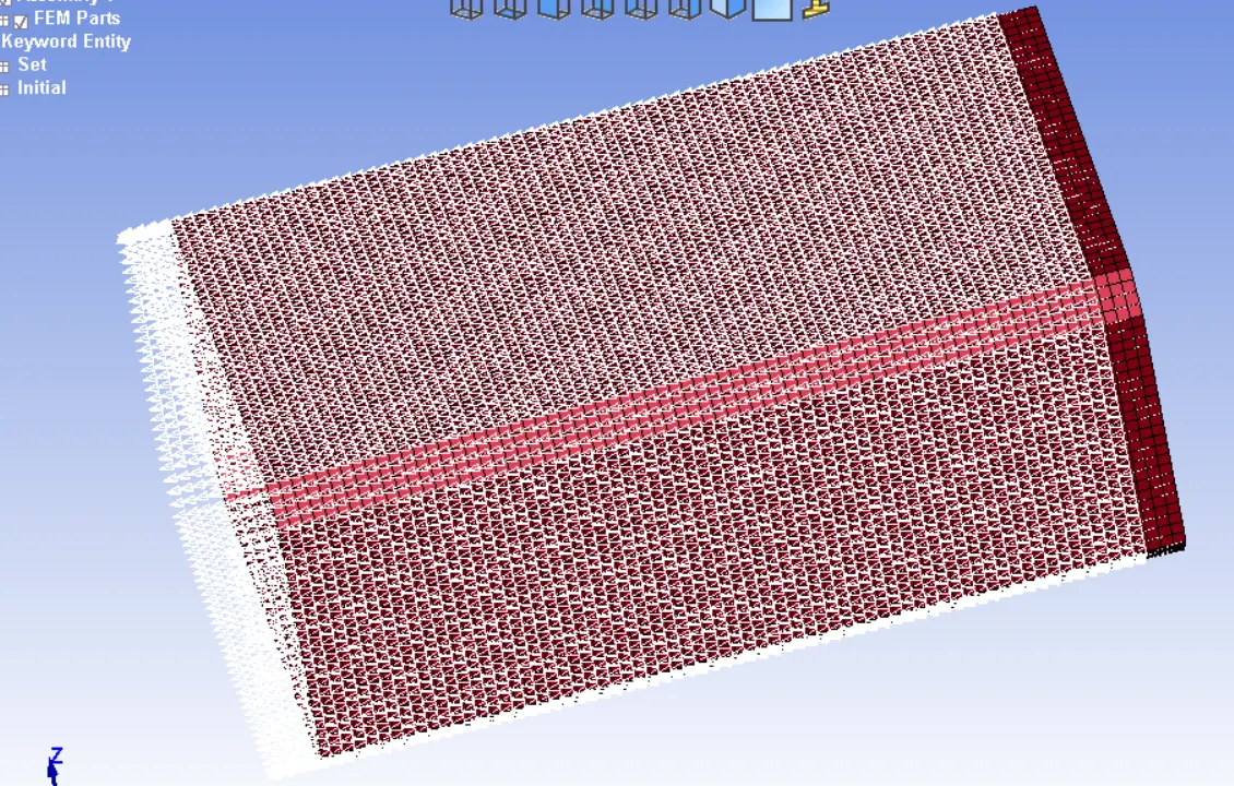
go to right pannel >> Model and Part >> Create Entity >> Initial >> Velocity >> Select the elements of crasg box >> Vx = 13. 88 mm/ms [50 kmph = 13.88 mm/ss] >> Apply >> Done
b) Rigid Wall
go to right pannel >> Model and Part >> Create Entity >> Rigidwall >> Create >> Planar >> GeoVector >> 1N+NL >> select a node at the edge of x axis >> change x distance such that the rgid plane will be at distance of 10 mm from CRASH BOX >> Apply >> Done
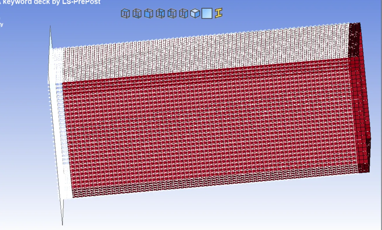
7) Contact Card Creation
go to right pannel >> Model and Part >> Keyword manager >> all >> CONTACT >> AUROMATIC_SINGLE_SURFACE >> Title = SELF_CONTACT_CRASH_BOX >> FS = 0.08 >> FD = 0.08 >> Accept >> Done
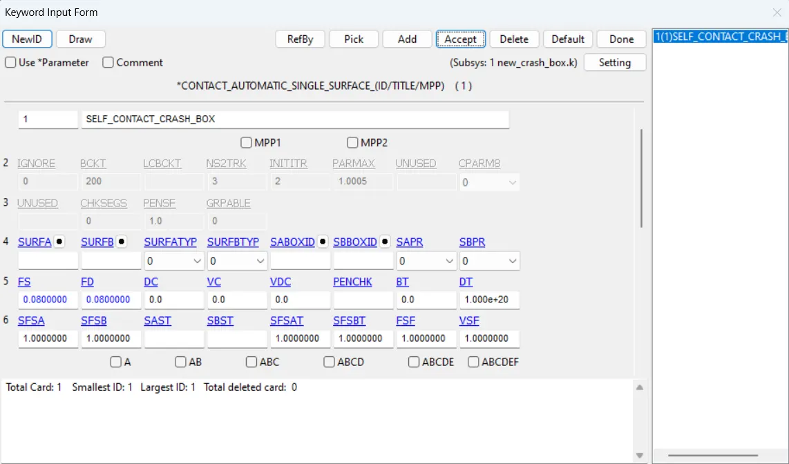
8) CONTROL CARD CREATION (ENERGY and TERMINATIOMN)
a) Define control energy as follows
go to right pannel >> Model and Part >> Keyword manager >> all >> CONTROL >> ENERGY
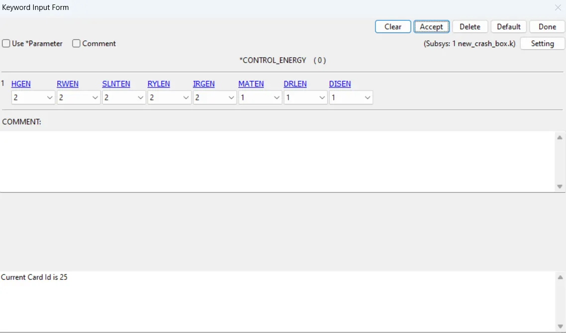
b) Give Termination end time 3 ms
go to right pannel >> Model and Part >> Keyword manager >> all >> CONTROL >> TERMINATION
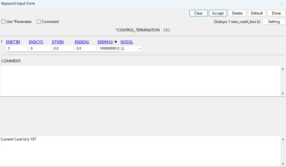
9) DATABASE
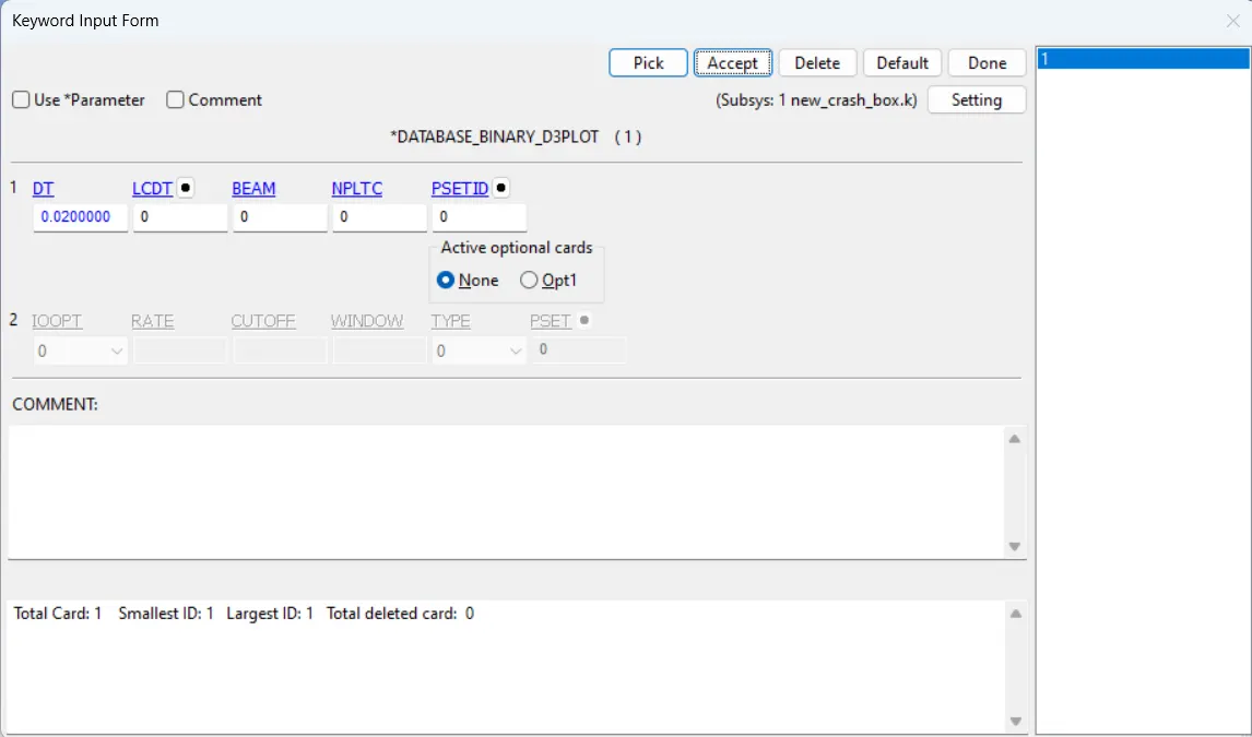
a) go to right pannel >> Model and Part >> Keyword manager >> all >> DATABASE >> BINARY_D3PLOT >> DT = 0.02 >> Accept >> Done
b) go to right pannel >> Model and Part >> Keyword manager >> all >> DATABASE >> ASCII_Option >> Select ELOUT, GLSTAT, MATSUM, SLEOUT, NODOUT, SECFORC and give value of DT = 0.02 for them >> Accept >> Done
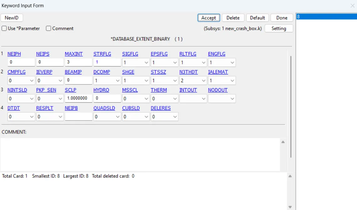
c) go to right pannel >> Model and Part >> Keyword manager >> all >> DATABASE >> EXTENT_BINARY >> STRFLG = 1 (to compute elastic strain in model)
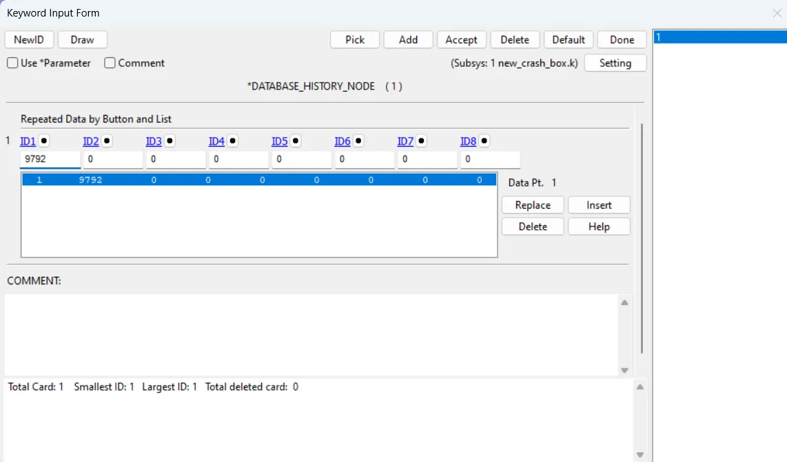
d) go to right pannel >> Model and Part >> Keyword manager >> all >> DATABASE >> HISTORY_NODE [ to calculate acceleration] >> insert a node >> accept >> Done
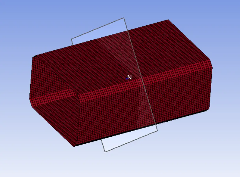
e) go to right pannel >> Model and Part >> Create Entity >> DATABASE >> CROSS_SECTION>> select nodes to create cross section >> Apply >> Done
10) MODEL CHECK
go to right pannel >> Model Check >> Keyword check
11) Save the file with .k extension. We have two run the simulation for two thickness , 1st 1.2 mm and 2nd 1.5 mm. Therefore after saving file change the thickness value and save as this another .k extension file .
12) Simulation
Open LS -Run >> select the file >> run the simulation
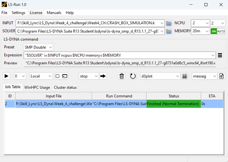
do this for both thickness file.
13) POST ANALYSIS
Open the binary file of the both thickness in different LS PRE-POST window and analyse the result.
Result:
1) Open D3plot binary file in LS Pre-Post
go to file >> open >> binary file >> select d3plot file >> open
2) Go to right pannel >> post >> analyse the result
V - m stress contour for thickness 1.2 mm
V - m stress contour for thickness 1.5 mm
Effective Plastic Strain contour for thickness 1.2 mm
Effective Plastic Strain contour for thickness 1.5 mm
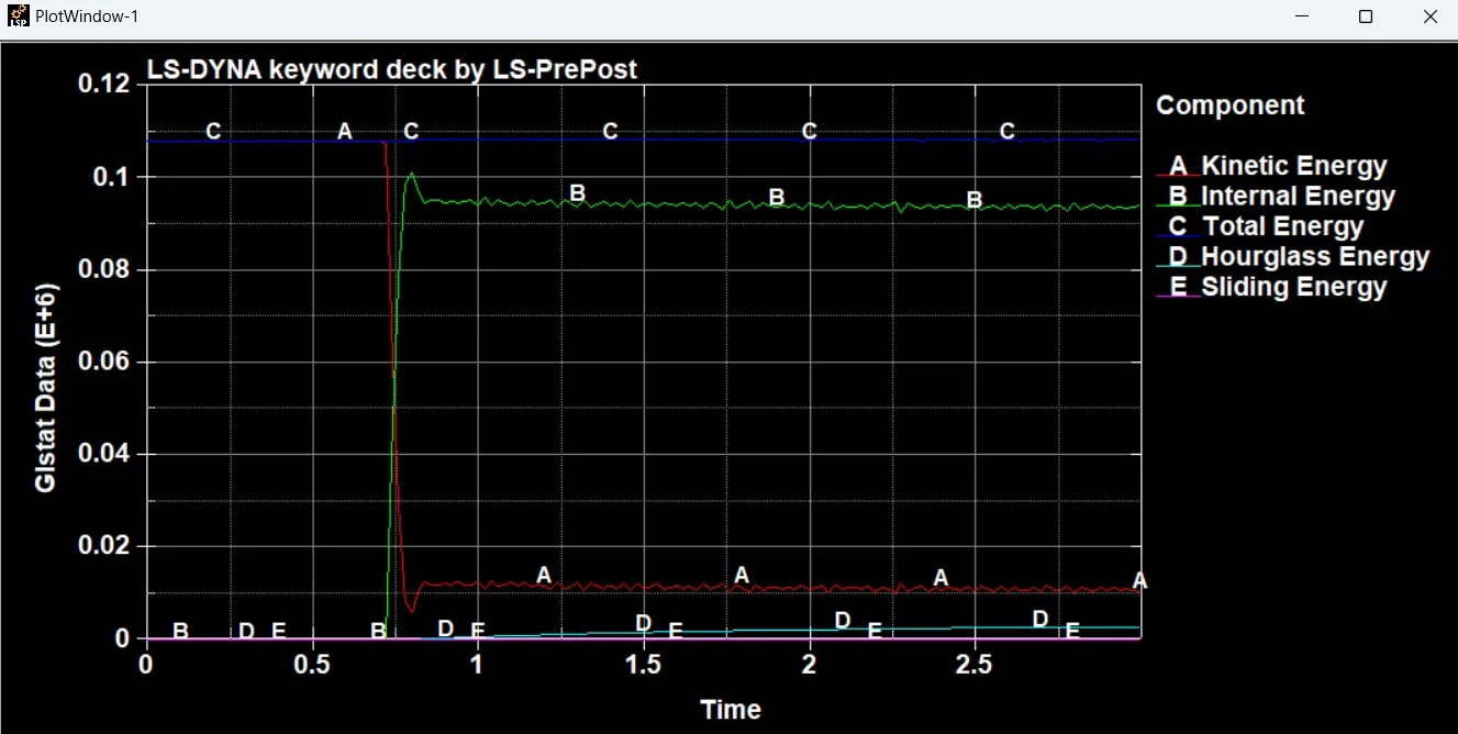
Graph for the energies for thickness 1.5 mm
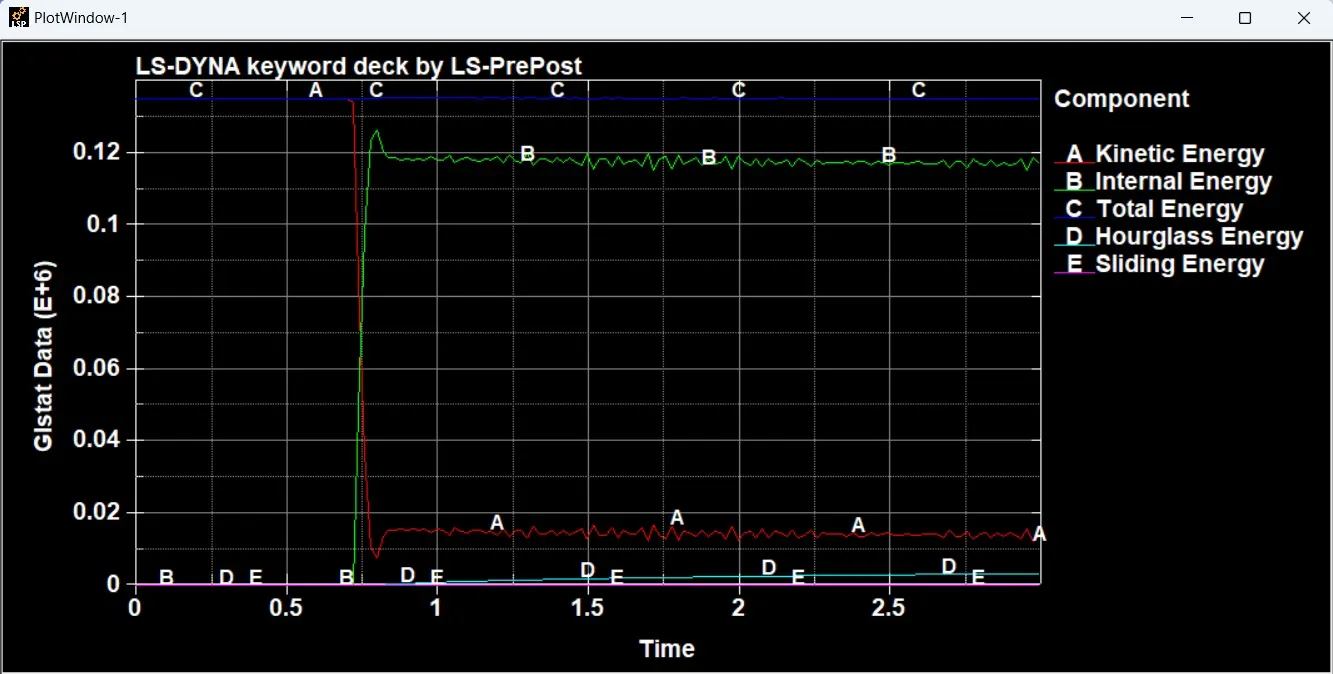
Graph for the energies for thickness 1.2 mm
Section force for thickness 1.5 mm
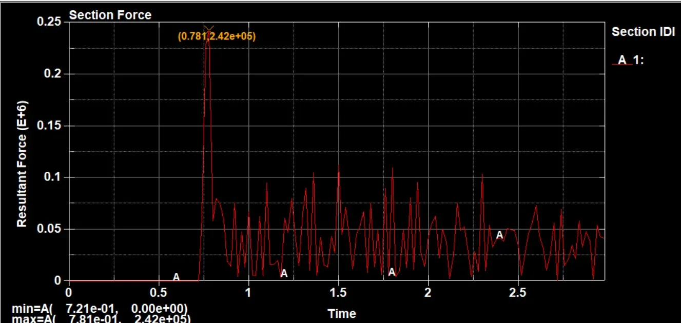
Section force for thickness 1.2 mm
Acceleration plot of a node in the middle of the crash box (along its length) for thickness 1.5 mm
Acceleration plot of a node in the middle of the crash box (along its length) for thickness 1.2 mm
Max von Miss Stress for thickness 1.2 mm is 3.789e+02
Max effective strain thickness 1.2 mm is 1.918e-02
Max von Miss Stress for thickness 1.5 mm is 1.928e-02
Conclusion:
Thus, we have successfully completed the given project.