Week - 4 - Crash Box Simulation
Aim:
To create a complete simulation file for crash analysis of a crash box having two different thicknesses of 1.2 mm and 1.5 mm from the given FE model of the crash box and produce the following deliverables.
- Input. k file and output files (D3PLOT, GLSTAT, SLEOUT, RCFORC)
- Animation of the final simulation
- Cross-sectional force generated in the middle of the crash box (along its length)
- Acceleration plot of a node in the middle of the crash box (along its length)
- Maximum directional stress and strain along the length of the crash box (X strain, Y strain, etc.)
- Plot of all energies (total, internal, kinetic, hourglass, sliding)
- Compare the accelerations and stress/strain plots of 1.2/1.5mm crash boxes.
Procedure:
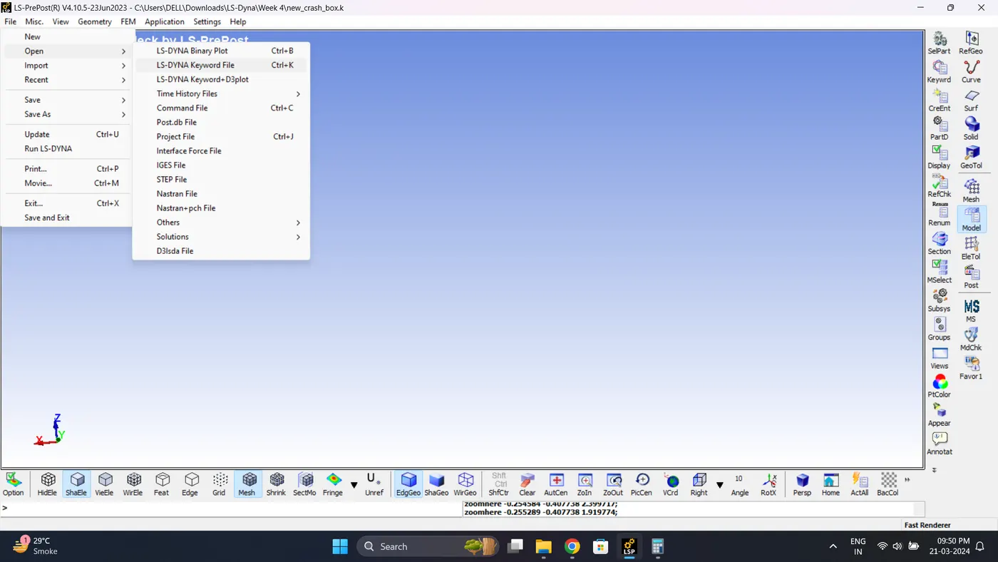
1. Import the .k file. Go to File - Import - LS-DYNA Keyword File.
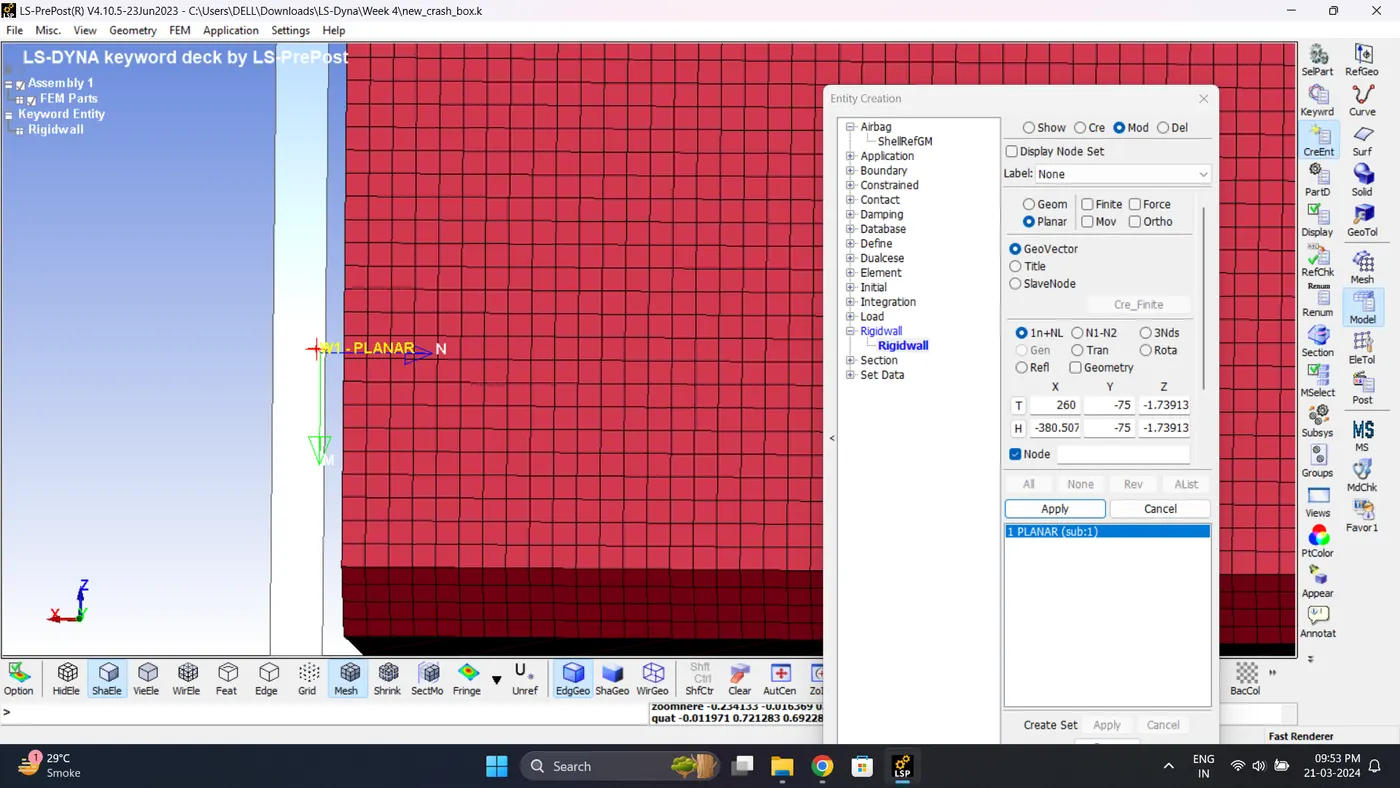
2. Create a Rigid wall. Go to Model - Create Entity - Rigid wall.
Note: Rigid wall normal should be perpendicular to Box.
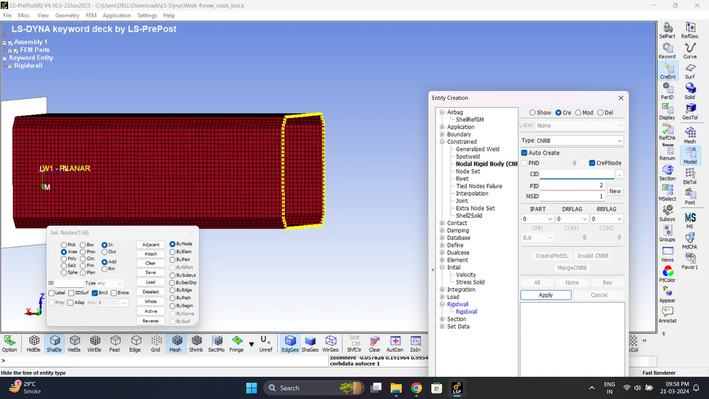
3. Create a CNRB. Go to Model - Create Entity - Constrianed - Nodal Rigid Body (CNRB).
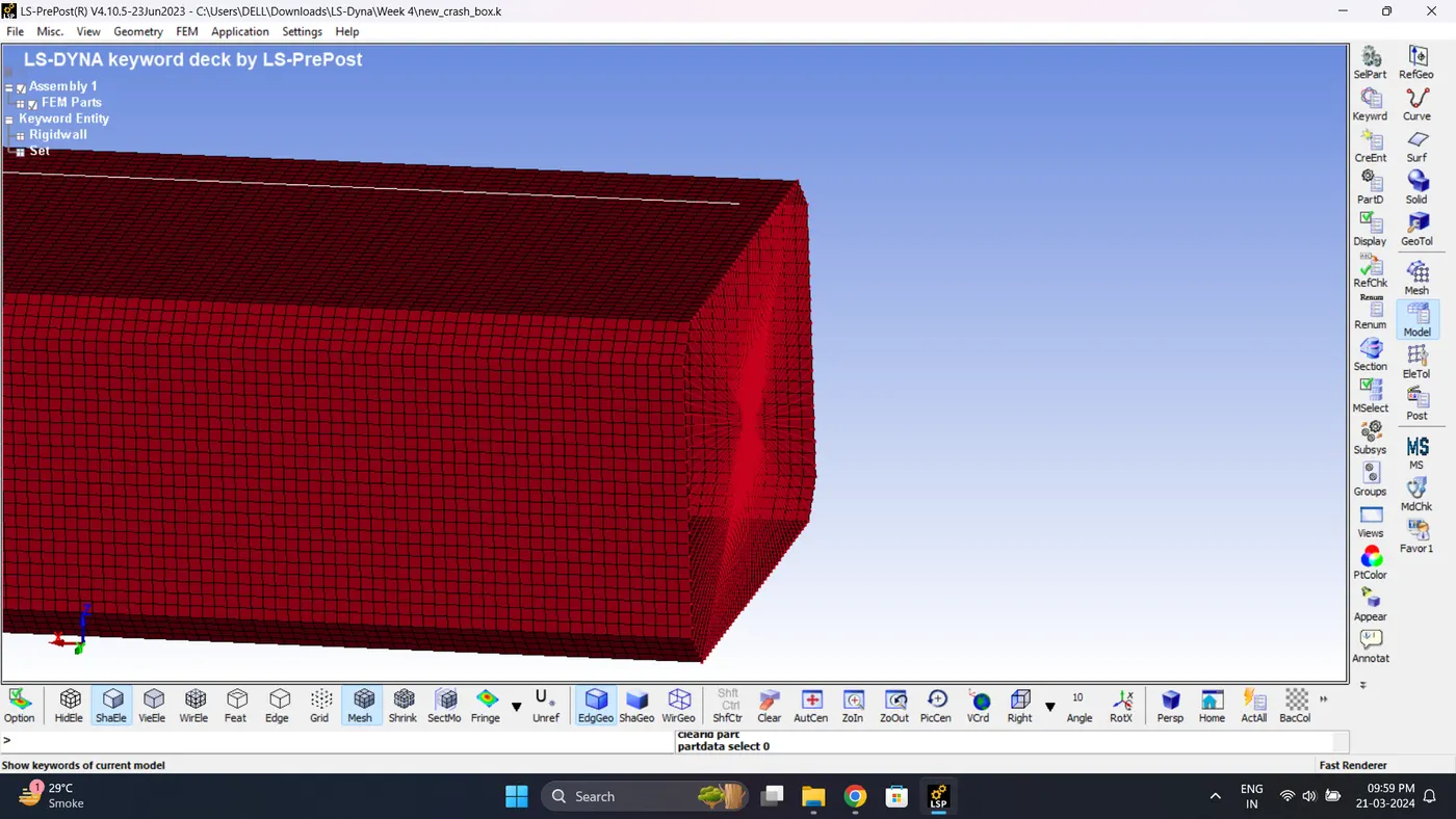
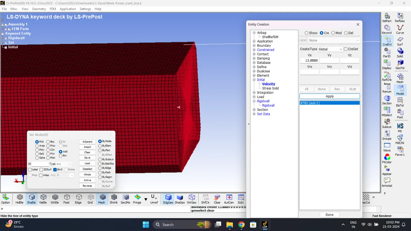
4. Give Initial Velocity. Go to Model - Create Entity - Initial - Velocity.
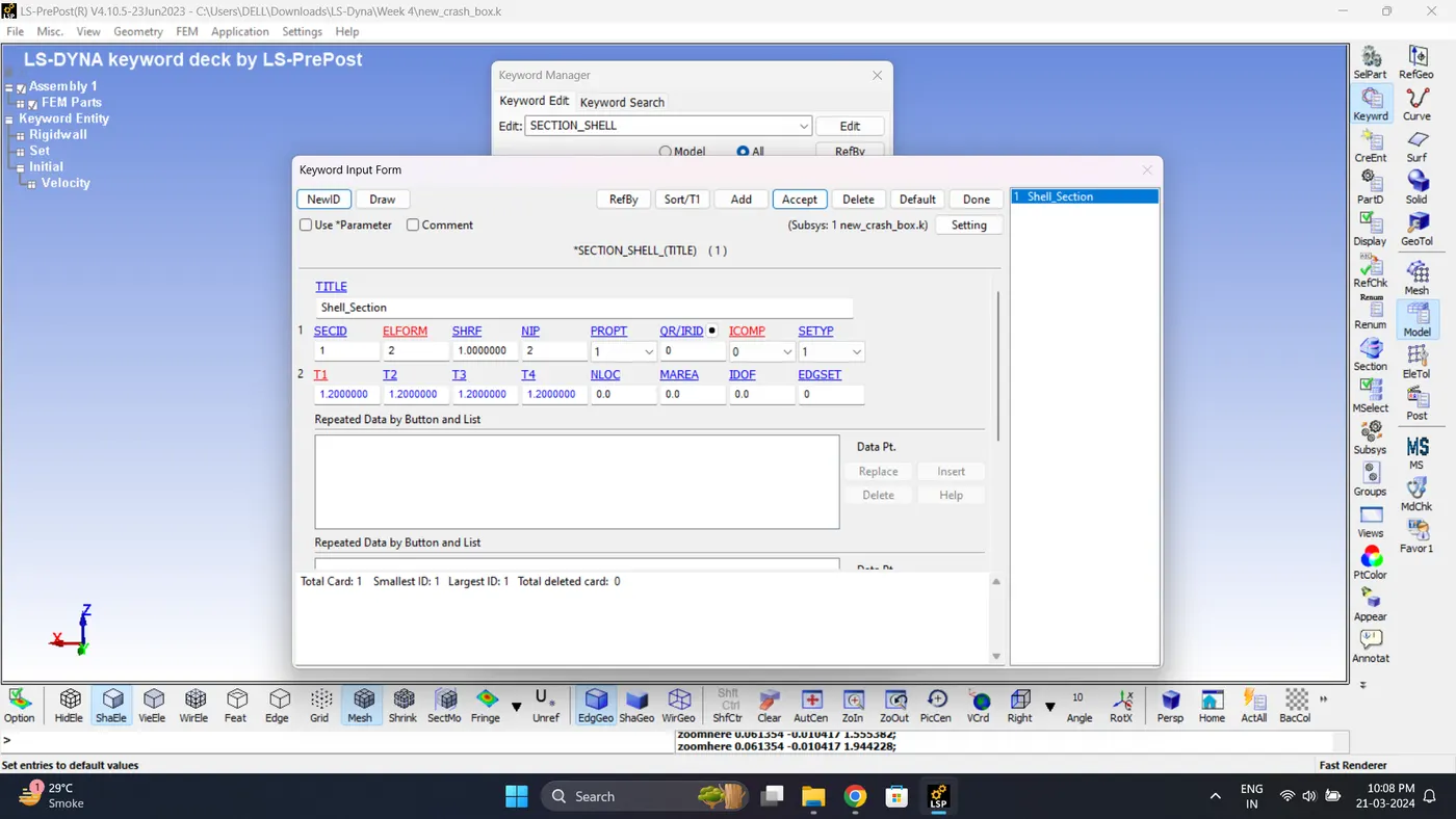
5. Create a section for shell. Go to Model - Keyword Manger - Section - Shell.
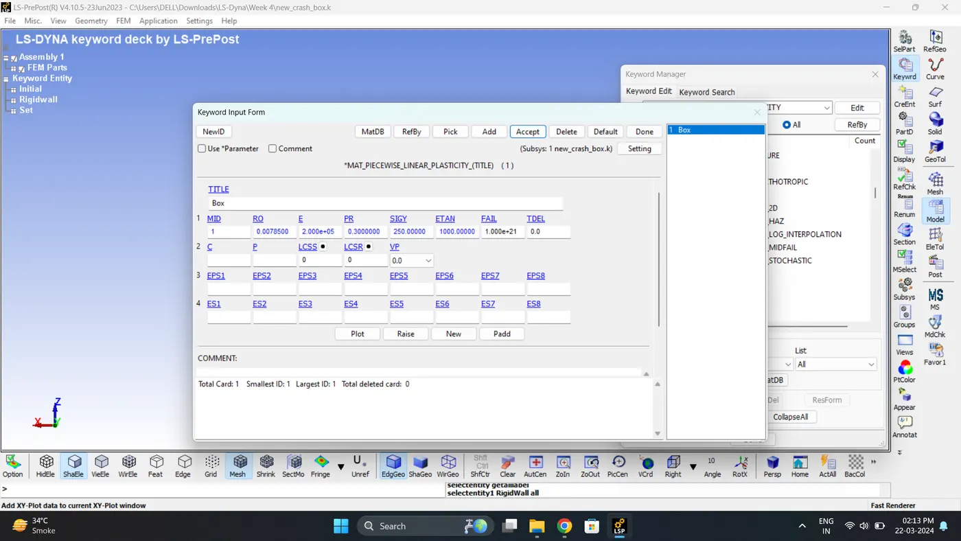
6. Create a Material card of Box. Go to Model - Keyword Manger - MAT - 024_Piecewise_Linear_Plasticity.
7. Create a Hourglass control card. Go to Model - Keyword Manger - Hourglass.
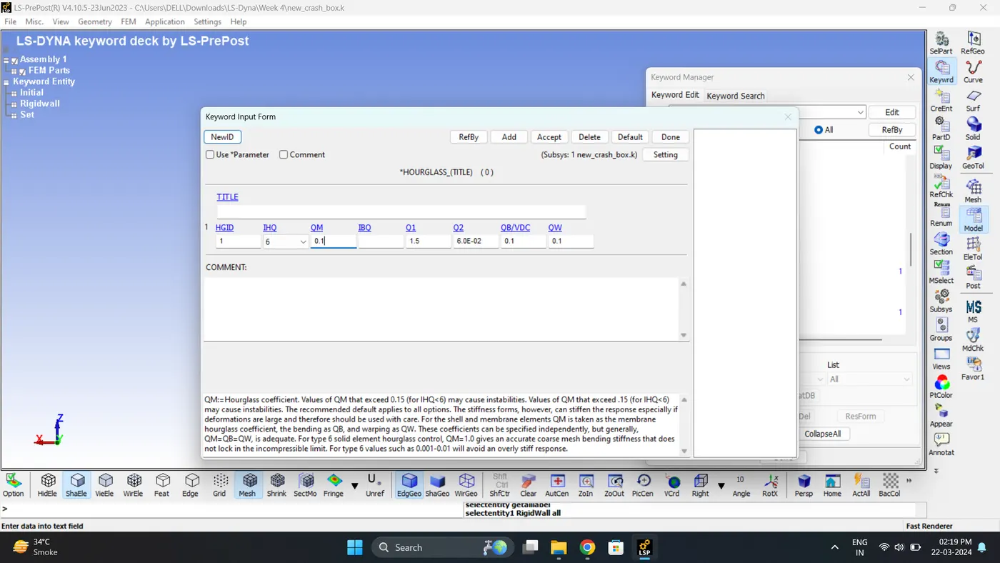
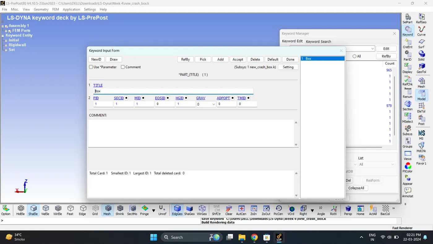
8. Assign section, Material, Hourglass to Part Box.
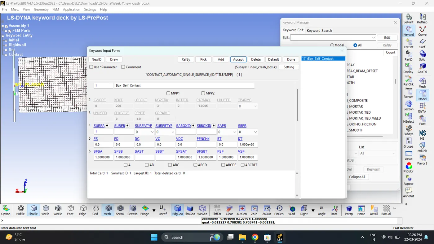
9. Create a Self Contact of Box. Go to Model - Keyword Manager - Contact - Automatic_Single_Surface.
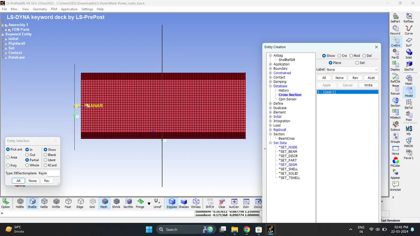
10. Create a Cross-Section to measure the sectional forces. Go to Model - Create entity - Database - Cross section.
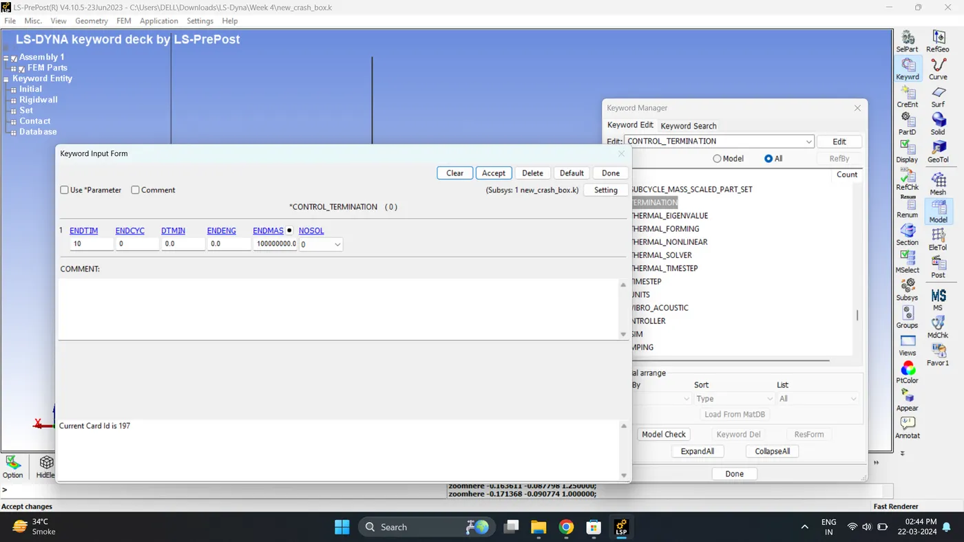
11. Create a Control Termination card. Go to Model - Keyword Manager - Control - Termination.
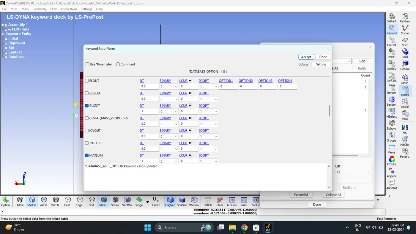
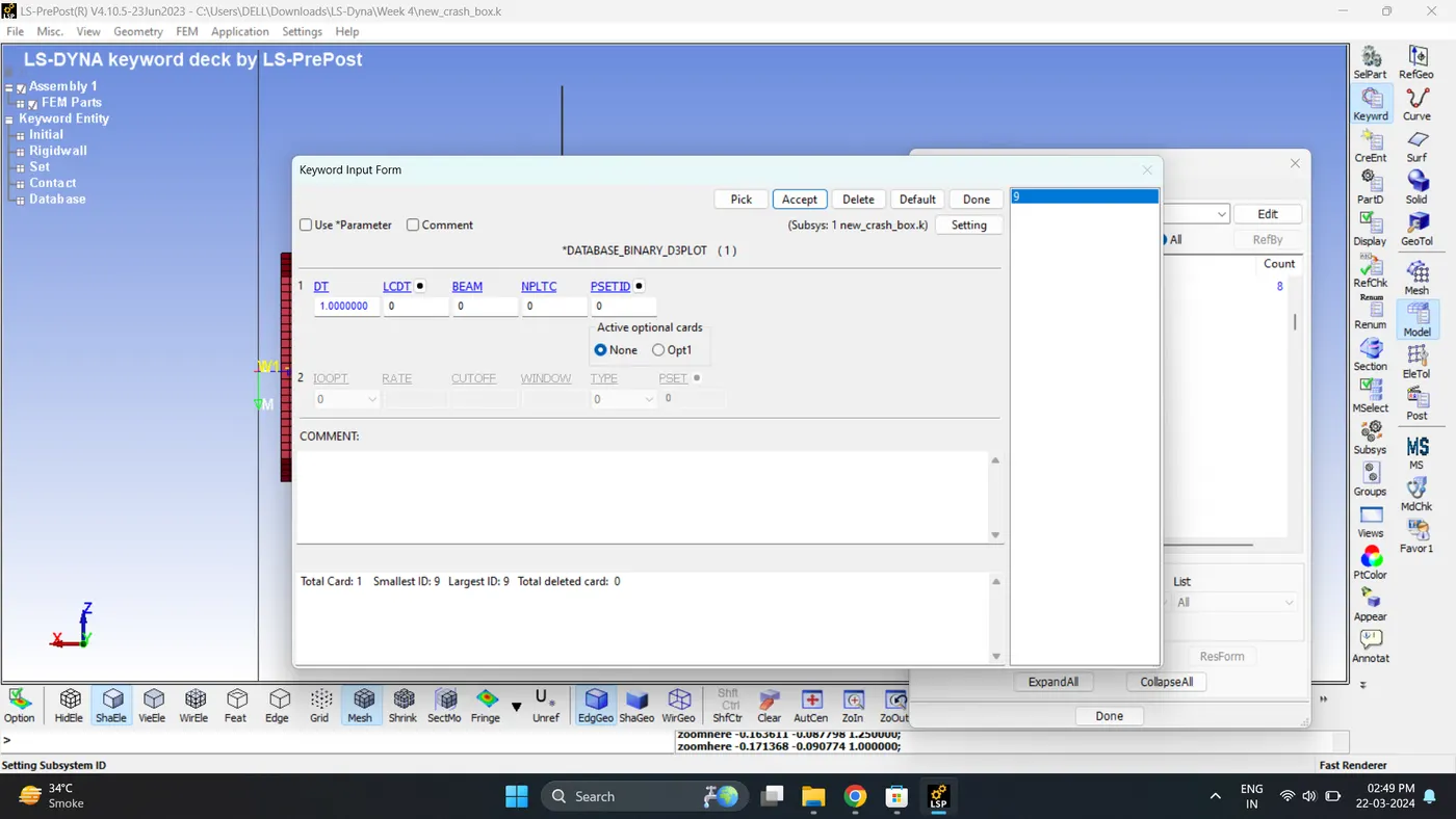
12. Create a Output request card. Go to Model - Keyword Manager - Database - ASCII_option / D3Plot.
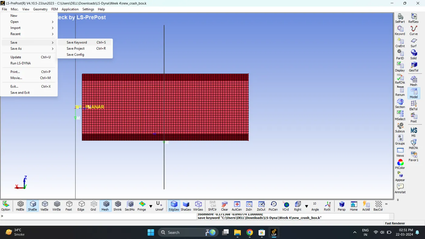
13. Save the Keyword File. Go to File - Save - Save Keyword.
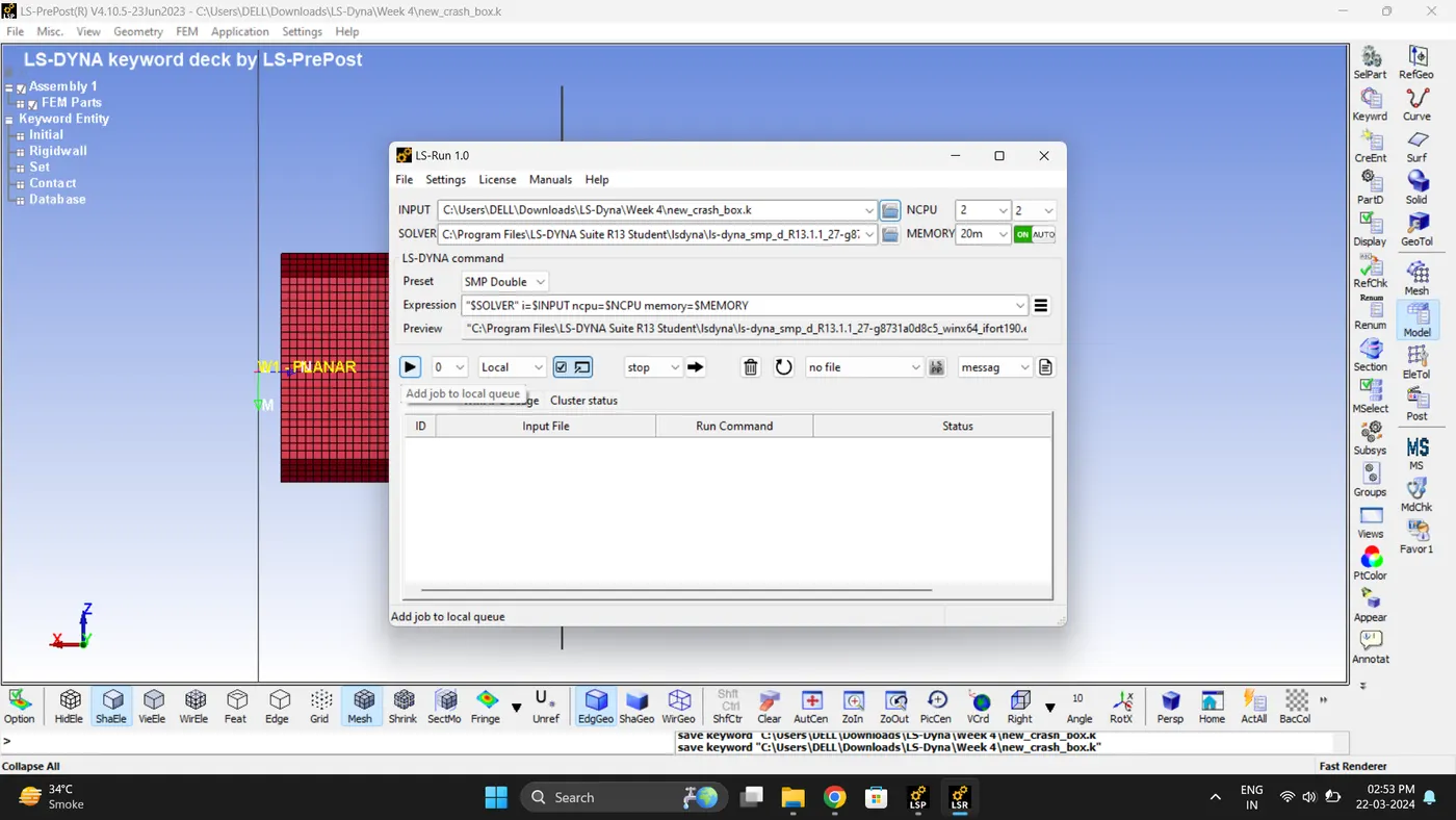
14. Run the Simulation. Open LS_Run - Select File - Click Add job to local queue.
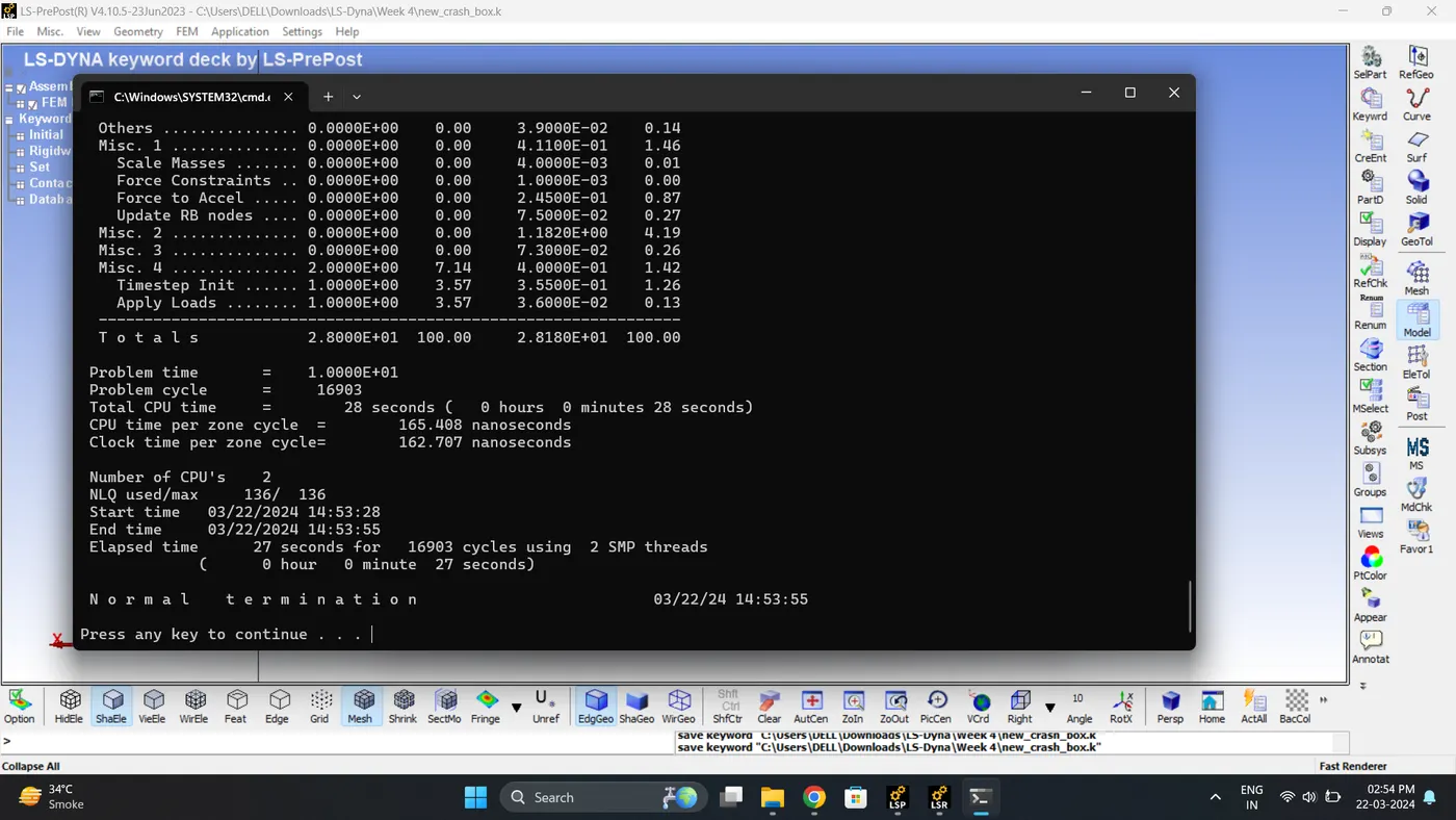
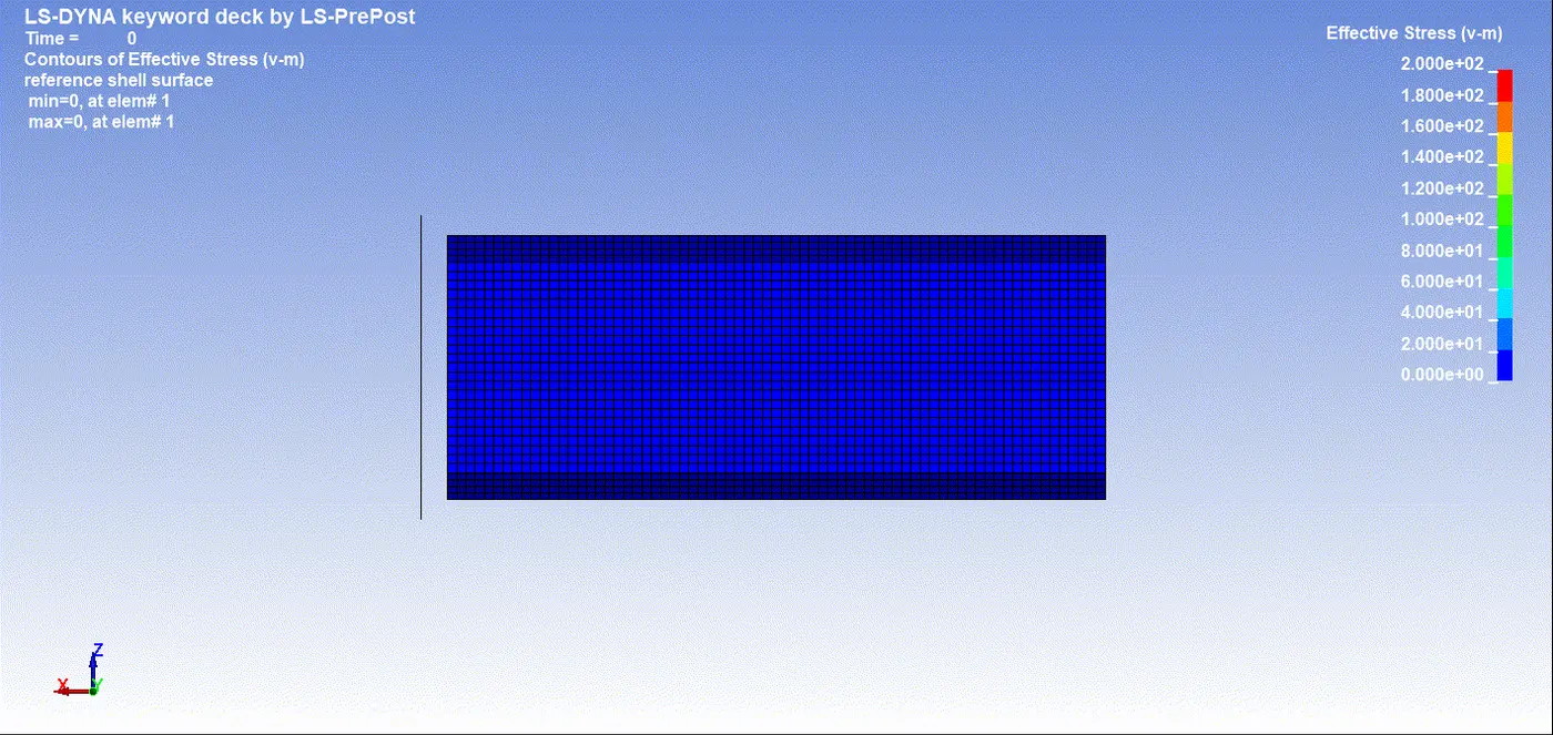
15. Open the Keyword and D3_plot in Ls-PrePost. Play the simulation and contour the von mises stress.
Max Vin mises stress = 194.154 gm/mm*ms^2.
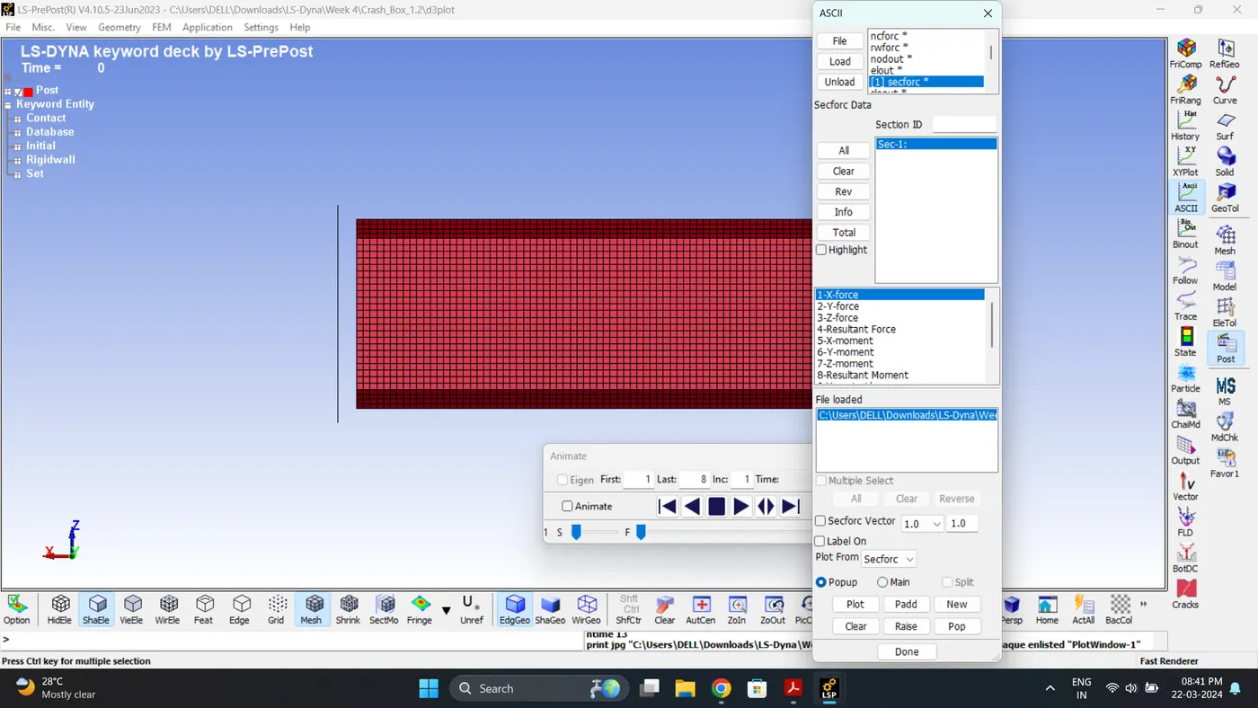
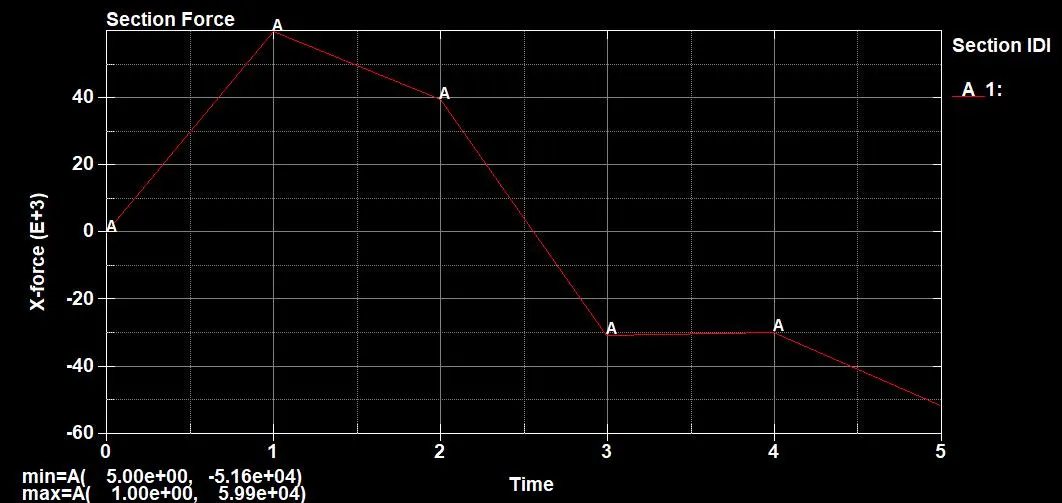
16. Plot the Cross-Sectional Force generated at the middle Section.
Maximum section force = 5.99e+04 gm*mm/ms^2.
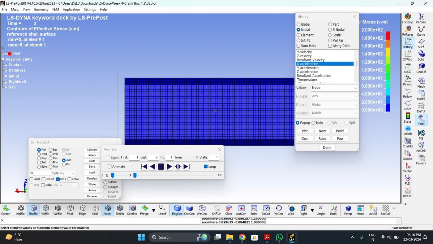
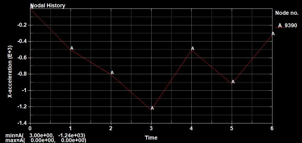
17. Plot the acceleration of Node (Middle Node).
Max Acceleration = 1.24e+03 mm/ms^2.
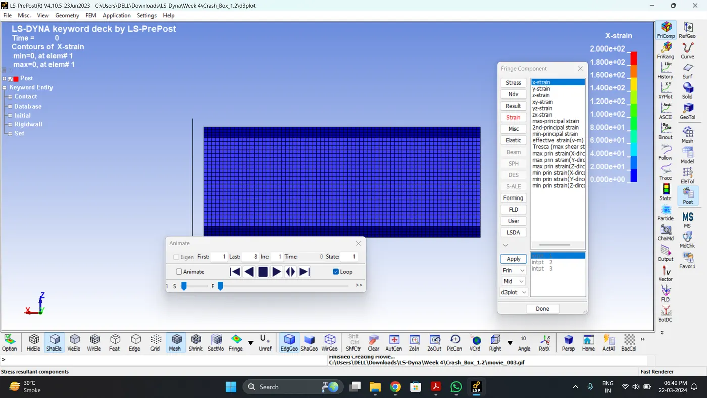
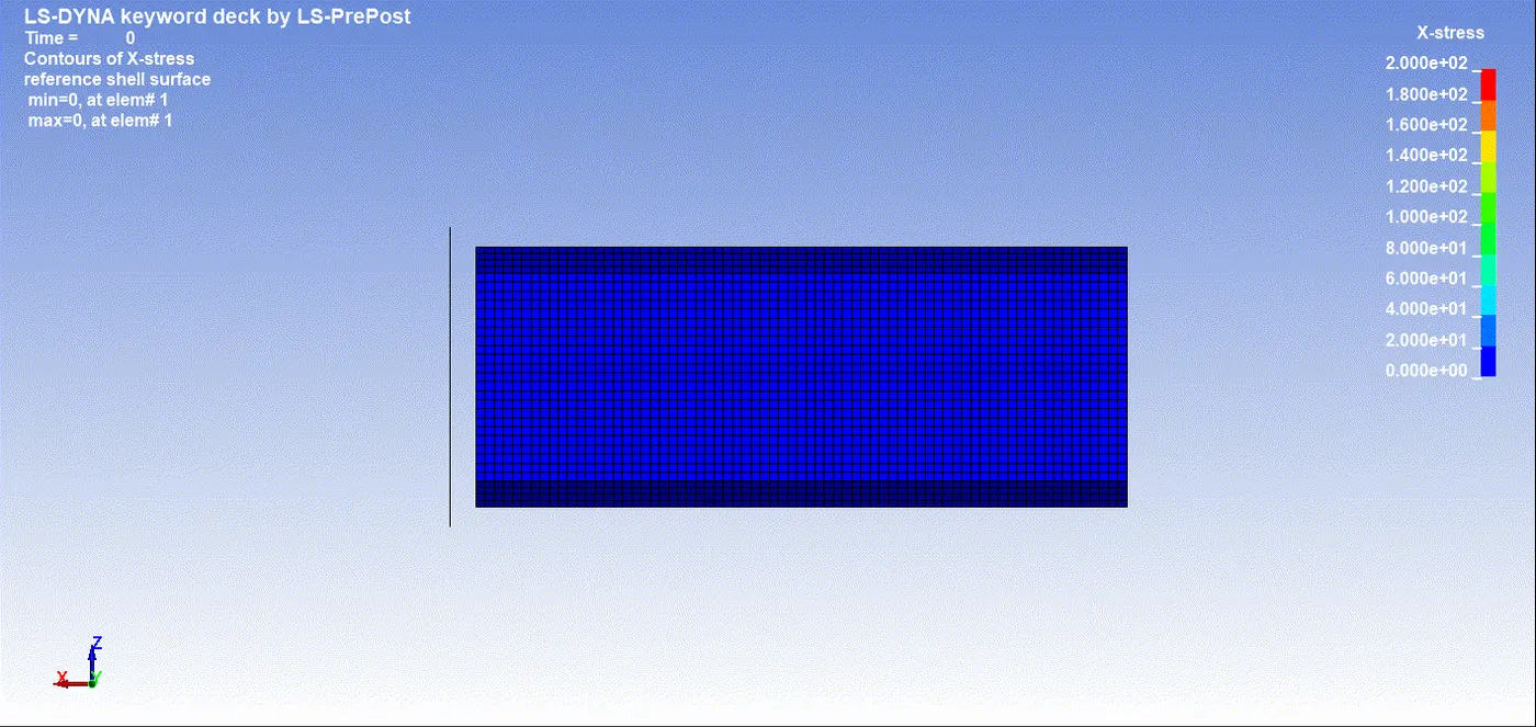
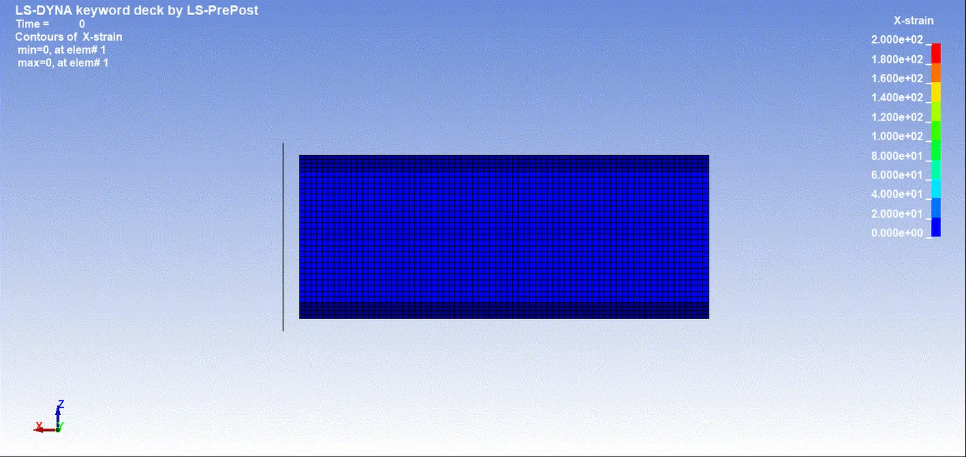
18. Plot the Maximum directional (X) stress and strain along the length.
Max Stress (X) = 159.648 gm/mm*ms^2.
Max Strain (X) = 0
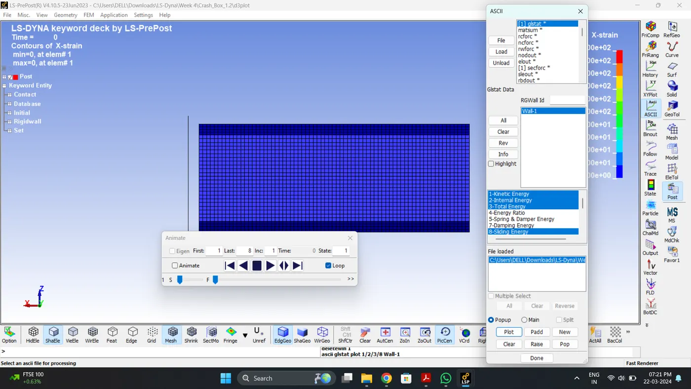
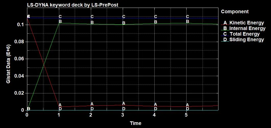
19. Plot all the energies.
| Sr.no | Name | Minimum | Maximum |
| 1 | Kinetic Energy | 4.28e+03 gm*mm^2/ms^2 | 1.08e+05 gm*mm^2/ms^2 |
| 2 | Internal Energy | 2.00e-20 gm*mm^2/ms^2 | 1.02e+05 gm*mm^2/ms^2 |
| 3 | Sliding Energy | 0 | 0 |
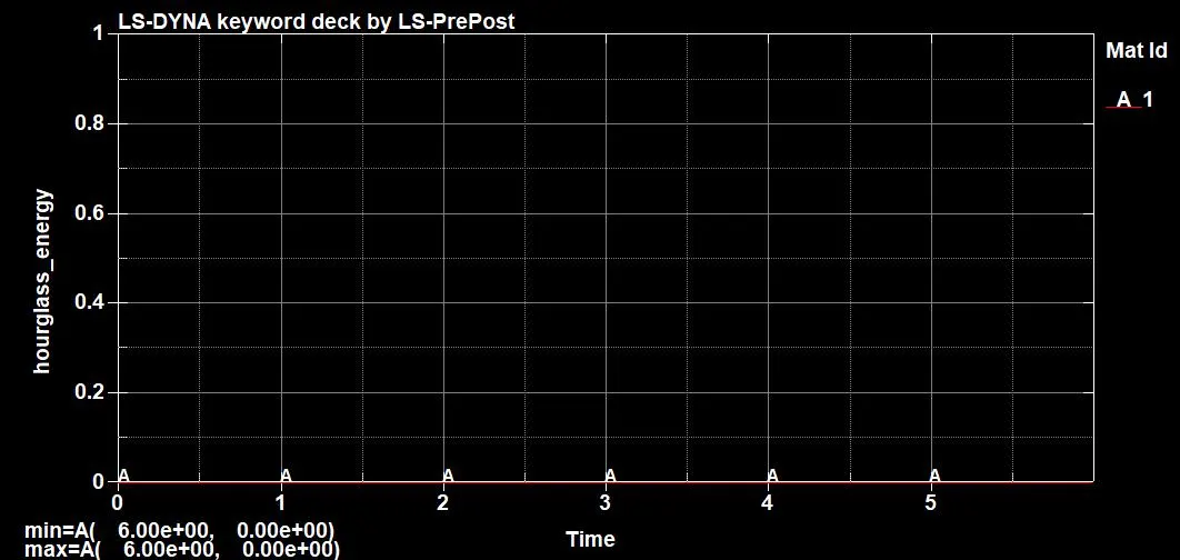
| 4 | Hourglass Energy | 0 | 0 |
| 5 | Total Energy | 1.08e+05 gm*mm^2/ms^2 | 1.08e+05 gm*mm^2/ms^2 |
| 6 | Stress (X) | 0 | 159.648 gm/mm*ms^2 |
| 7 | Strain (X) | 0 | 0 |
| 8 | Acceleration | 0 | 1.24e+03 mm/ms^2 |
| 9 | Section Force | 0 | 5.99e+04 gm*mm/ms^2 |
| 10 | Von Mises Stress | 0 | 194.154 gm/mm*ms^2. |
At initial Kinetic Energy is high after impact kinetic energy reduces and internal energy increases. It is seen that sliding, Hourglass and Total Energy is Constant. So we can say that simulation is fairly accurate.
20. Similarly run the simulation case 2, by changing the element thickness to 1.5 mm.
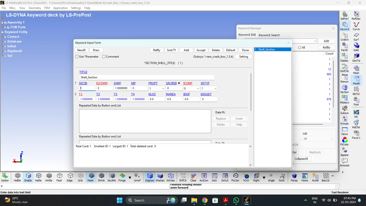
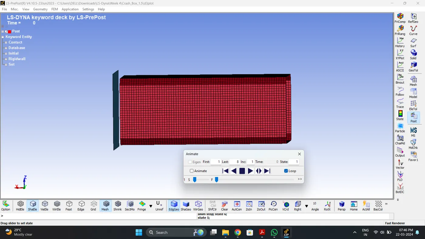
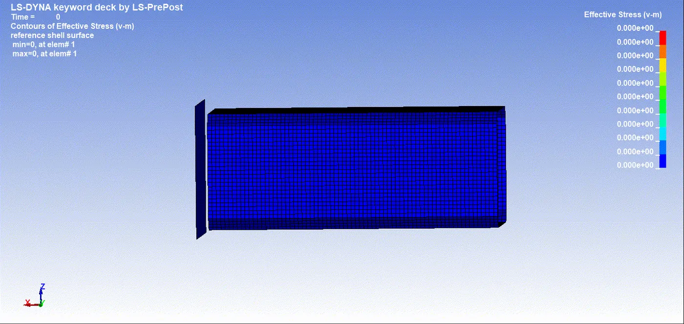
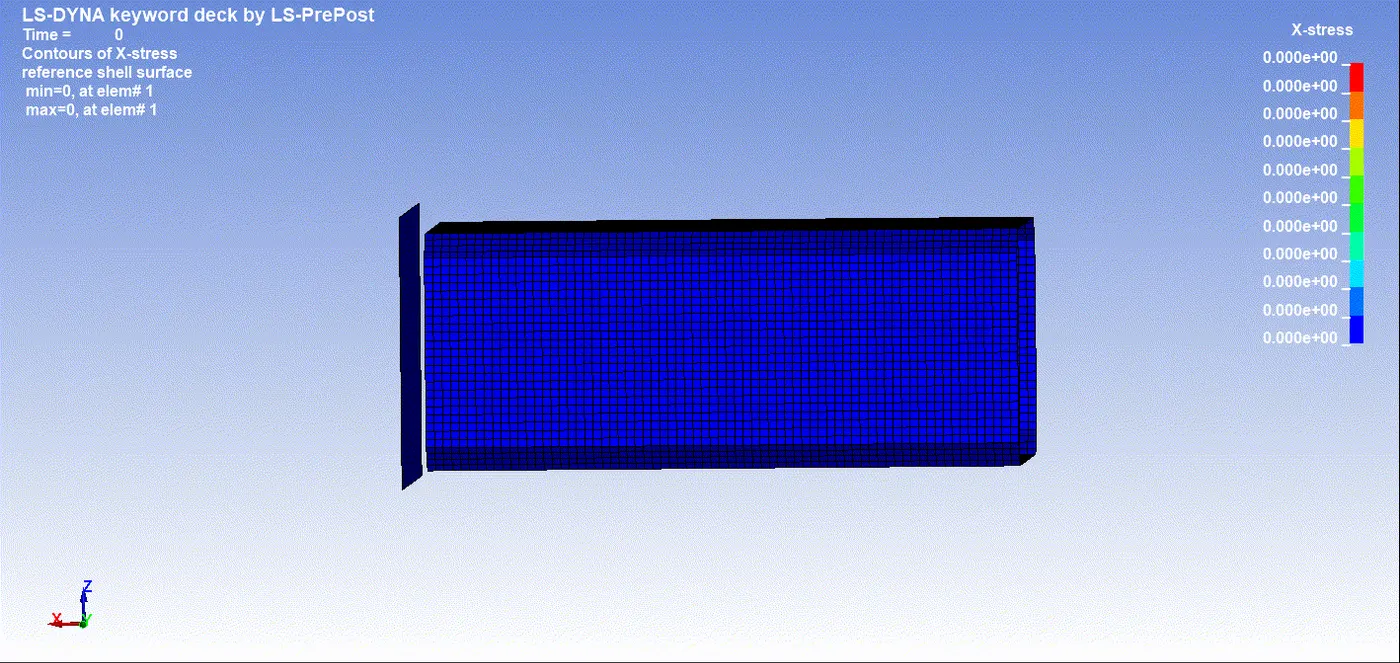
21. Similarly to Case 1 1.2 mm thickness box. Plot the contour of Von Mises, Stress and Strain.
Max Vin mises stress = 202.237 gm/mm*ms^2.
Max Stress (X) = 183.822 gm/mm*ms^2.
Max Strain (X) = 0
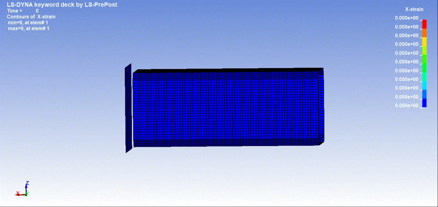
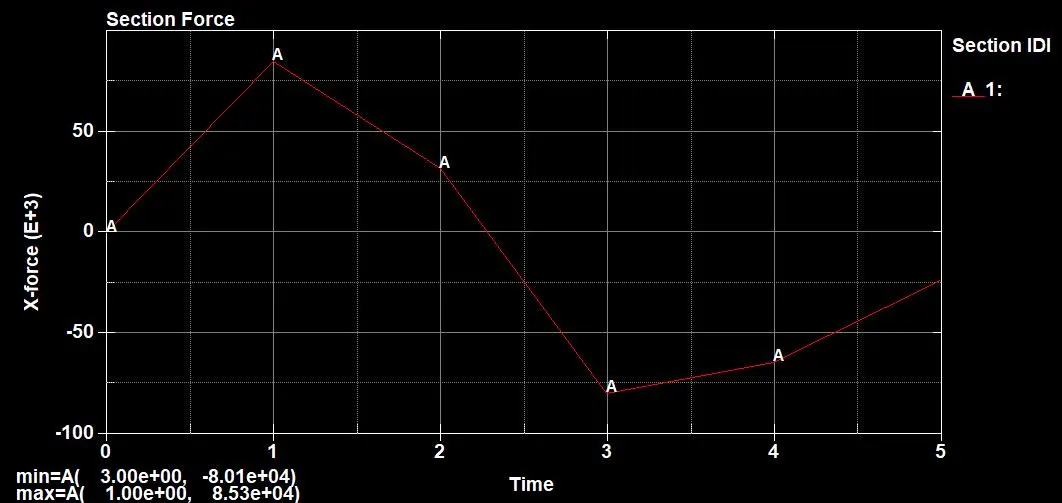
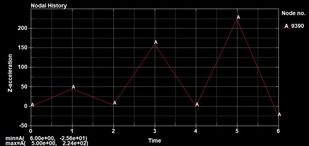
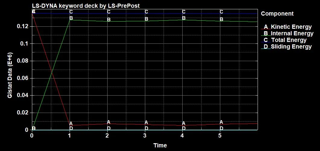
22. Similarly to Case 1 1.2 mm thickness box. Plot the Section Force, Acceleration, Internal Energy, Kinetic Energy, Sliding Energy, Hourglass Energy and Total Energy.
| Sr.no | Name | Minimum | Maximum |
| 1 | Kinetic Energy | 5.49e+03 gm*mm^2/ms^2 | 1.35e+05 gm*mm^2/ms^2 |
| 2 | Internal Energy | 2.00e-20 gm*mm^2/ms^2 | 1.28e+05 gm*mm^2/ms^2 |
| 3 | Sliding Energy | 0 | 0 |
| 4 | Hourglass Energy | 0 | 0 |
| 5 | Total Energy | 1.35e+05 gm*mm^2/ms^2 | 1.35e+05 gm*mm^2/ms^2 |
| 6 | Stress (X) | 0 | 183.822 gm/mm*ms^2 |
| 7 | Strain (X) | 0 | 0 |
| 8 | Acceleration | 0 | 2.24e+02 mm/ms^2 |
| 9 | Section Force | 0 | 8.53e+04 gm*mm/ms^2 |
| 10 | Von Mises Stress | 0 | 202.237 gm/mm*ms^2 |
At initial Kinetic Energy is high after impact kinetic energy reduces and internal energy increases. It is seen that sliding, Hourglass and Total Energy is Constant. So we can say that simulation is fairly accurate.
Comparison:
Case 1: Element Thickness 1.2
| Sr.no | Name | Minimum | Maximum |
| 1 | Kinetic Energy | 4.28e+03 gm*mm^2/ms^2 | 1.08e+05 gm*mm^2/ms^2 |
| 2 | Internal Energy | 2.00e-20 gm*mm^2/ms^2 | 1.02e+05 gm*mm^2/ms^2 |
| 3 | Sliding Energy | 0 | 0 |
| 4 | Hourglass Energy | 0 | 0 |
| 5 | Total Energy | 1.08e+05 gm*mm^2/ms^2 | 1.08e+05 gm*mm^2/ms^2 |
| 6 | Stress (X) | 0 | 159.648 gm/mm*ms^2 |
| 7 | Strain (X) | 0 | 0 |
| 8 | Acceleration | 0 | 1.24e+03 mm/ms^2 |
| 9 | Section Force | 0 | 5.99e+04 gm*mm/ms^2 |
| 10 | Von Mises Stress | 0 | 194.154 gm/mm*ms^2 |
Case 2: Element Thickness 1.5
| Sr.no | Name | Minimum | Maximum |
| 1 | Kinetic Energy | 5.49e+03 gm*mm^2/ms^2 | 1.35e+05 gm*mm^2/ms^2 |
| 2 | Internal Energy | 2.00e-20 gm*mm^2/ms^2 | 1.28e+05 gm*mm^2/ms^2 |
| 3 | Sliding Energy | 0 | 0 |
| 4 | Hourglass Energy | 0 | 0 |
| 5 | Total Energy | 1.35e+05 gm*mm^2/ms^2 | 1.35e+05 gm*mm^2/ms^2 |
| 6 | Stress (X) | 0 | 183.822 gm/mm*ms^2 |
| 7 | Strain (X) | 0 | 0 |
| 8 | Acceleration | 0 | 2.24e+02 mm/ms^2 |
| 9 | Section Force | 0 | 8.53e+04 gm*mm/ms^2 |
| 10 | Von Mises Stress | 0 | 202.237 gm/mm*ms^2 |
It is seen from the above results, Due to increase in element thickness
- Acceleration after impact decreases due to increase in thickness of component.
- Section forces after impact increases in thickness of component.
- Stress generated after impact also increases in thickness of component.
- Von mises stress also increases in thickness of component.
- Since there are no deformation in both the cases strain value remains 0.
Conclusion:
Crash Box simulation are run successfully.