Week - 4 - Crash Box Simulation
OBJECTIVE: To simulate the crashbox FE model in three different cases using different thickness, different loads and material cards in LS DYNA.
PROCEDURE:
CASE 1: crash box is simulated in such a way that it is given an initial velocity and the material property as purely elastic with section thickness as 1.2mm.
Create the node set for all the nodes of crash box for initiating the velocity for simulation and create a midplane cross section for post results
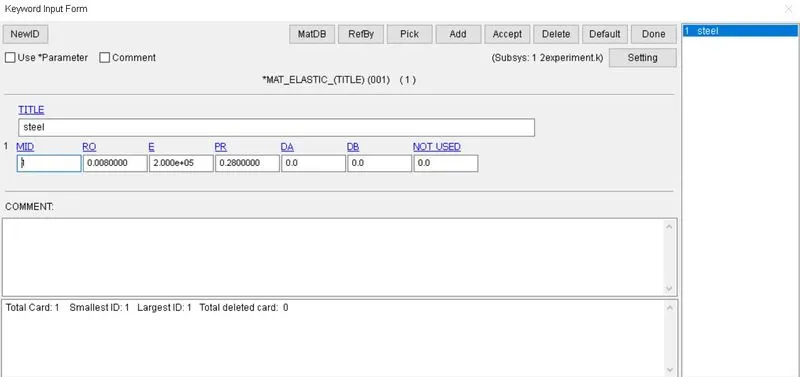
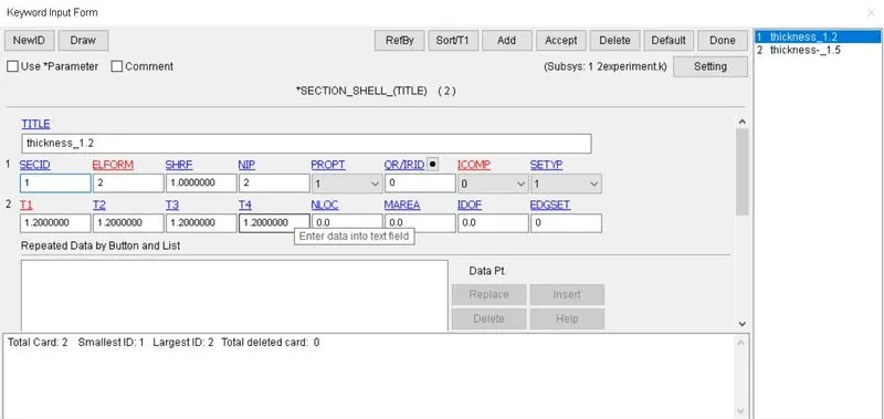
and the material and section ID is given as shown below.
create the self contact by automatic single surface card by using master and slave as the same part.
and selected the desired results in database.
and given the initial velocity for the nodeset.
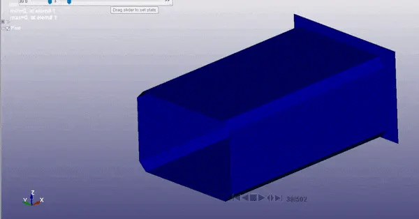
the simulation occured as shown below.
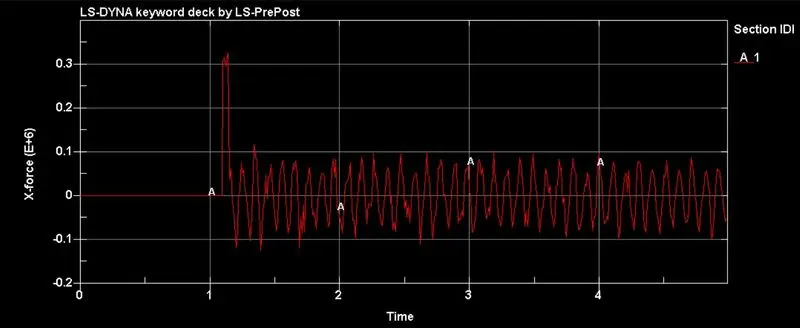
X force at mid plane plot is shown below.
nodal acceleration in the middle of the crashbox along its length as shown below.
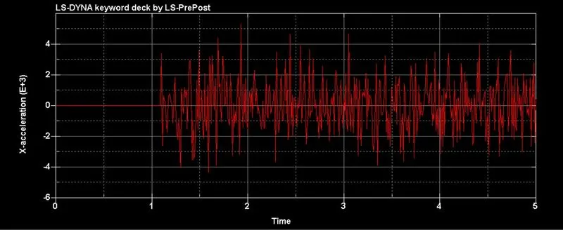
you can see that contact has happened
Max stress along the direction of length is shown below.
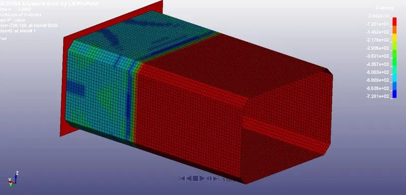
Max strain along the directio of length is shown below.
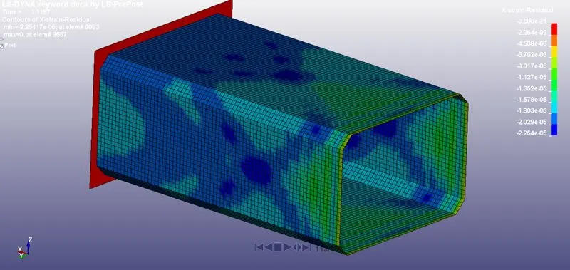
Internal energy, kinetic energy and total energy plots are shown below.
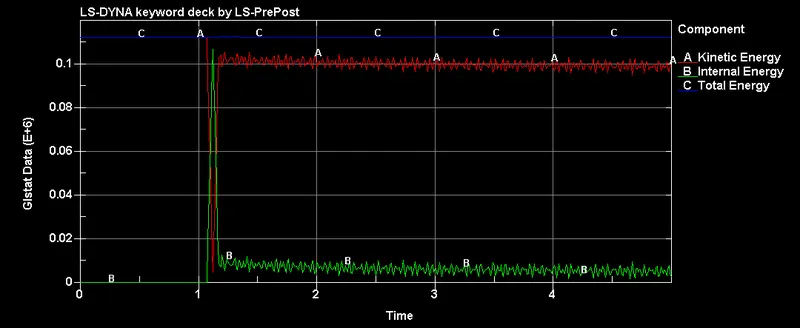
Hourglass energy plot is shown below.
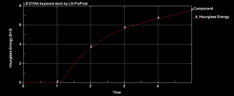
contact has happened at 1.1 ms and energy is increased from that point.
sliding energy is shown as below.
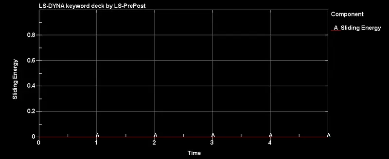
as there was no sliding the energy has not generated throughout the simulation.
case2:
In this case we use piecewise linear plasticity card for material and prescribed motion node for load with shell thickness 1.2mm.
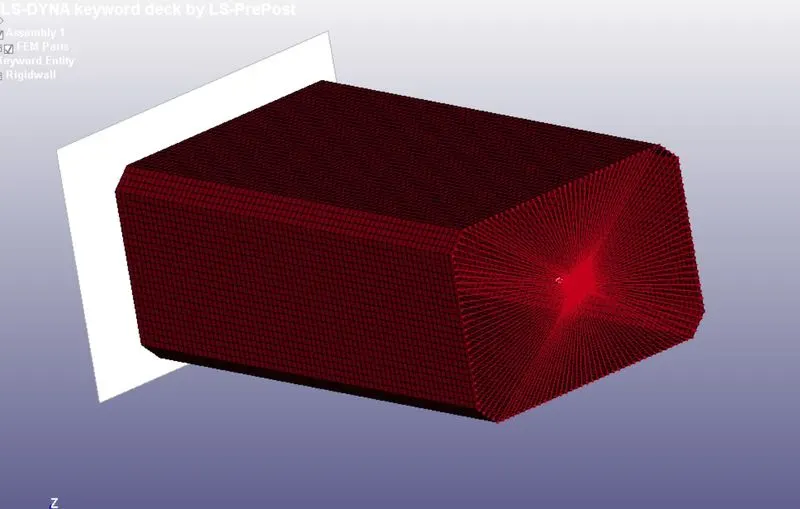
create the rigid wall using create entity as shown in case 1 and then create the CNRB as shown below.
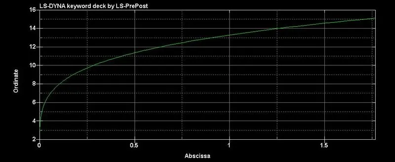
then create the curve the effective plastic strain by loading the XY data from csv file and plot the graph.
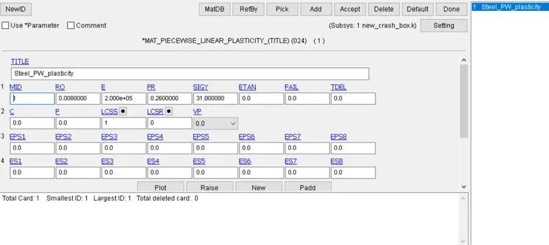
then give the MAT024 card inputs as shown below.
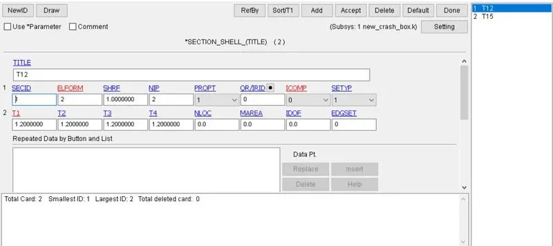
section with thickness 1.2mm with ELEFORM as 2 .
now assign the material and section to the part.
and create contact card for self contact as shown in case 1.
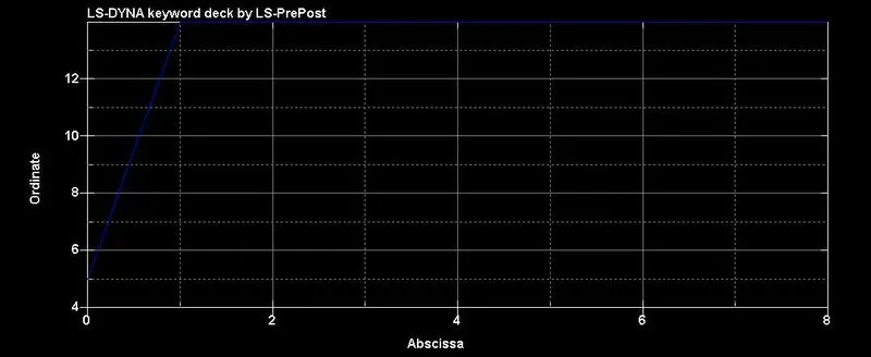
now create the curve for velocity load as shown below.
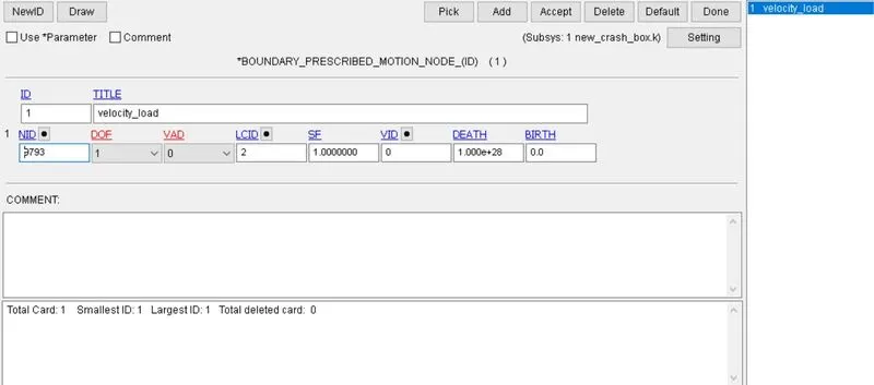
created the prescribed motion node for independent node of CNRB as below.
now mention the necessary database file with DT as 0.01.
save the keyword file and run the analysis.
the simulation was rendered as shown below.
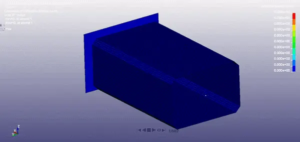
the crash box deformed due to continuous velocity load contrast to the simulation with initial velocity condition.
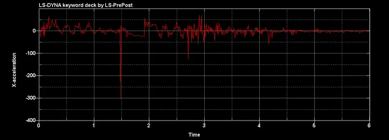
acceleration along the length at node on the middle of the crash box.
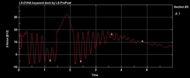
section force at midplane along the direction of length the force is fluctuating due to inertial forces created at the start of velocity load.
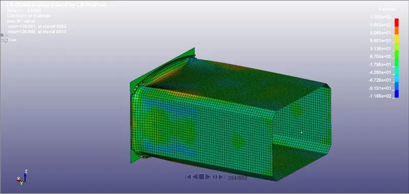
max stress along the direction of length is 1.166e2.
and strain corresponding to this contour is shown below.
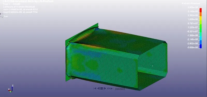
and the y- strain is shown below.
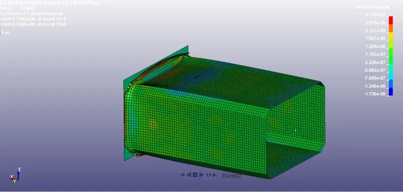
and the energy plots are given below.
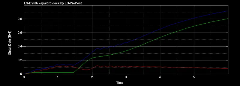
RED- kinetic energy, Blue- total energy, Green- internal energy.
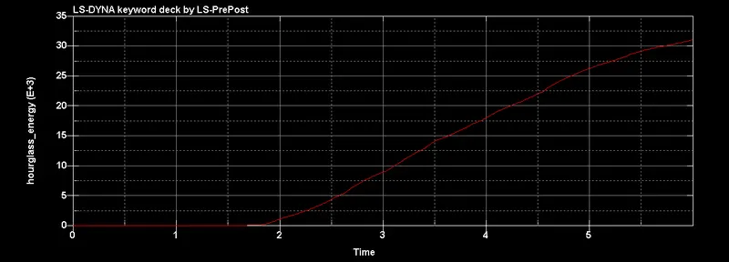
Hourglass energy
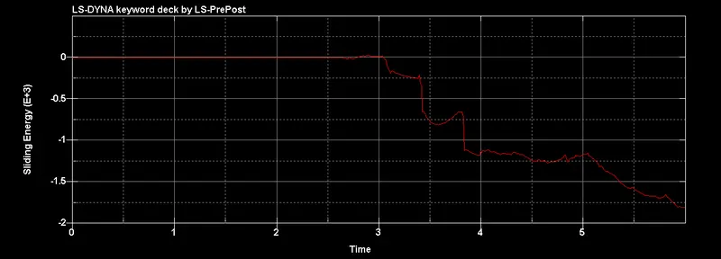
sliding energy.
case 3:
In this case we change the thickness of the shell and run the simulation with everything else the same.
thickness of the shell is changed to 1.5 mm.
the simulation occured as below.
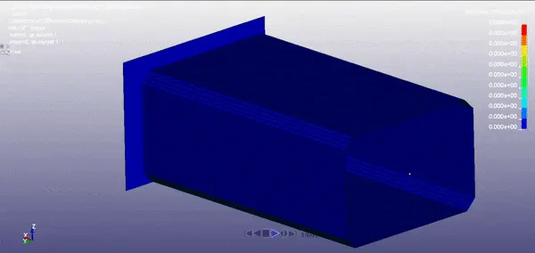
the result differed in the deformation of the element.
and the cross sectional forces are shown below.
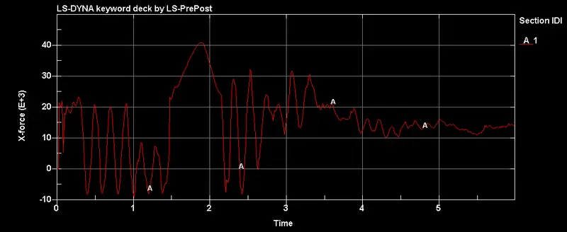
almost similar to the shell thickness 1.2 with slight change in magnitude.
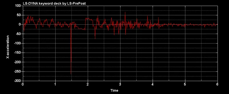
acceleration along the direction of length at node.
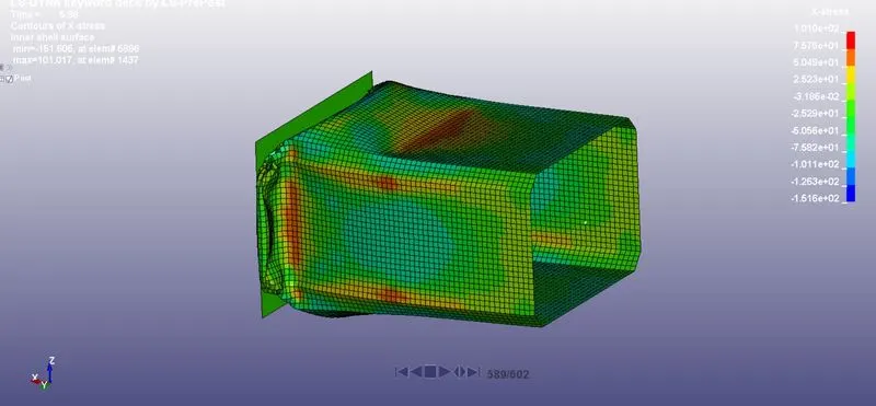
max stress contour and max stress is 1.516e2 in the negative X-direction.
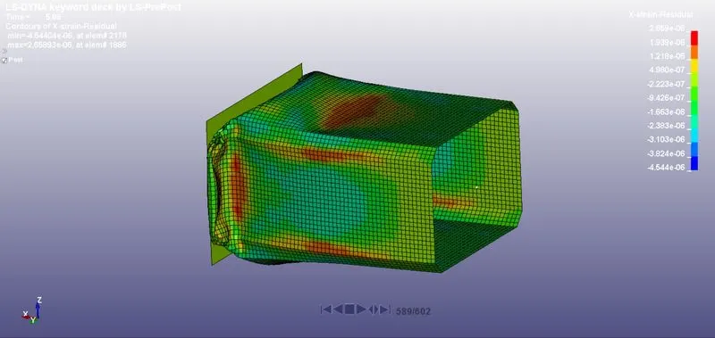 '
'
x-strain contour correlated to the max stress contour.
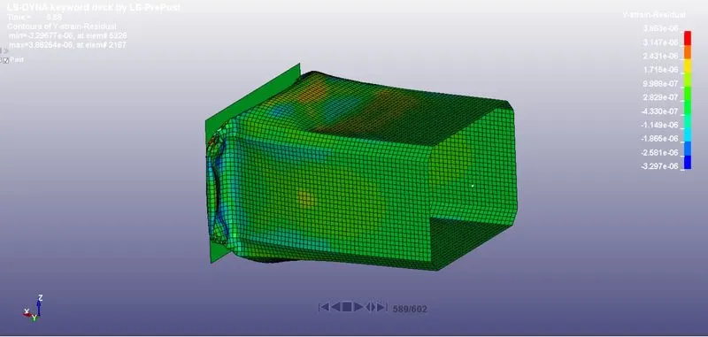
y-strain correlated to max X stres contour.
the energy plots are given below.
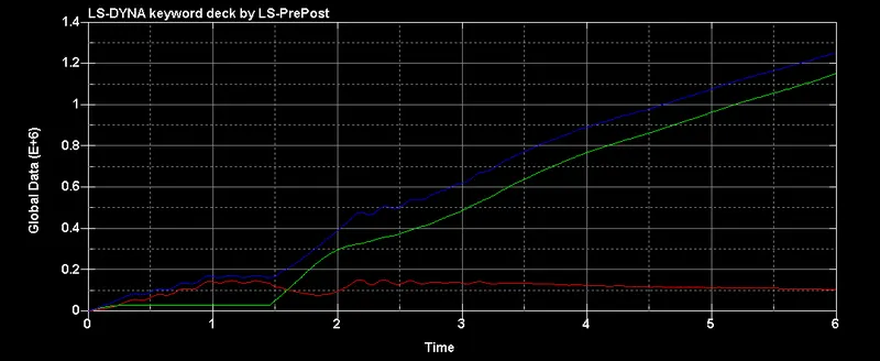
Red- kinetic energy, Green- internal energy, Blue- total energy.
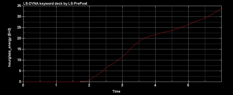
hourglass energy plot.
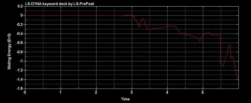
sliding energy plot.
comparison of acceleration of 1.2 mm and 1.5mm shell.
| crashbox | X acceleration | time | x strain | plastic strain | time |
| 1.2mm | 21.5 | 2.09 | 55.8 | 0.0239 | 2.37 |
| 1.5mm | 21.1 | 2.11 | 61.3 | 0.0248 | 2.22 |
CONCLUSION:
In this challenge I ran the simulation in two ways which has two different type of loads. one which was initial velocity load and the result was the crash box bounced back. and the other load is imposed velocity where crash box deformed at the rigid wall. and the material also changed from purely elastic steel to steel piecewise linear plasticity. I have observed changes in result due to different thickness and plot the necessary graphs.