To simulate the given crash box using LS-Dyna and to follow the assumptions and information that are given below:
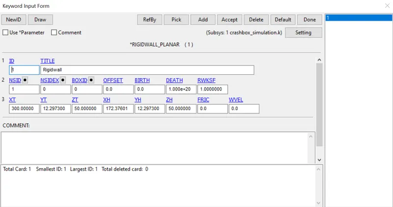
The crashbox should crash into a rigidwall created using *RIGIDWALL_ keyword. Check the manual to understand and create a rigidwall.
- Material for the crashbox is steel. The simulation needs to be started using elastic material to verify its correctness and later a nonlinear material card data will be provided. Thickness of the crashbox is 1.2mm.
- The simulation should satisfy either of the two situations - (1) It crashes on the rigidwall and rebounces completely or (2) it buckles and folds in the axial direction so as to come in self-contact.
- Once the simulation is completed and results as asked for below is collected, run another simulation by increasing the thickness of the crashbox from 1.2 to 1.5mm
Deliverables:
- Input .k file and output files (d3plot, glstat, sleout, rcforc)
- Animation of the final simulation
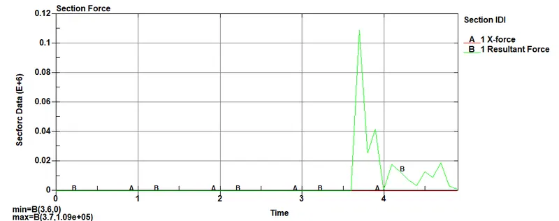
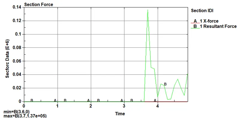
- Cross-sectional force generated in the middle of the crashbox (along its length)
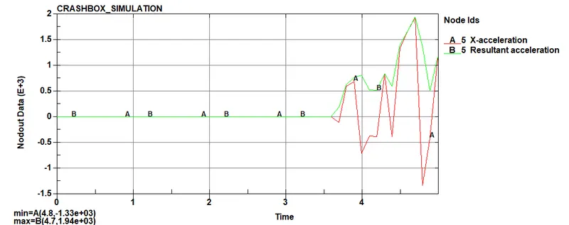
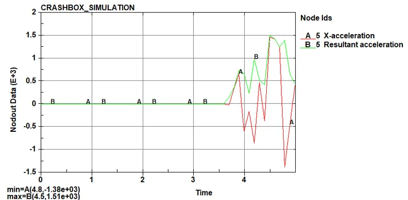
- Acceleration plot of a node in the middle of the crashbox (along its length)
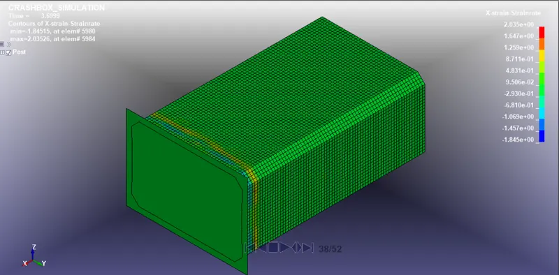
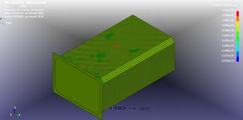
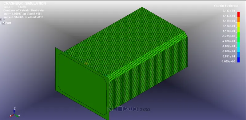
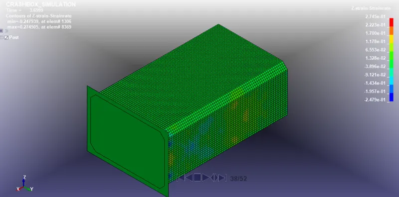
- Maximum directional stress and strain along the length of the crashbox (X strain, Y strain etc)
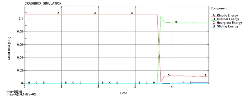
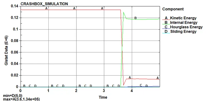
- Plot of all energies (total, internal, kinetic, hourglass, sliding)
- Compare the accelerations and stress/strain plots of 1.2/1.5mm crashboxes.
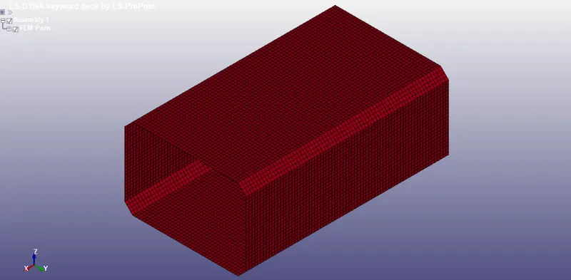
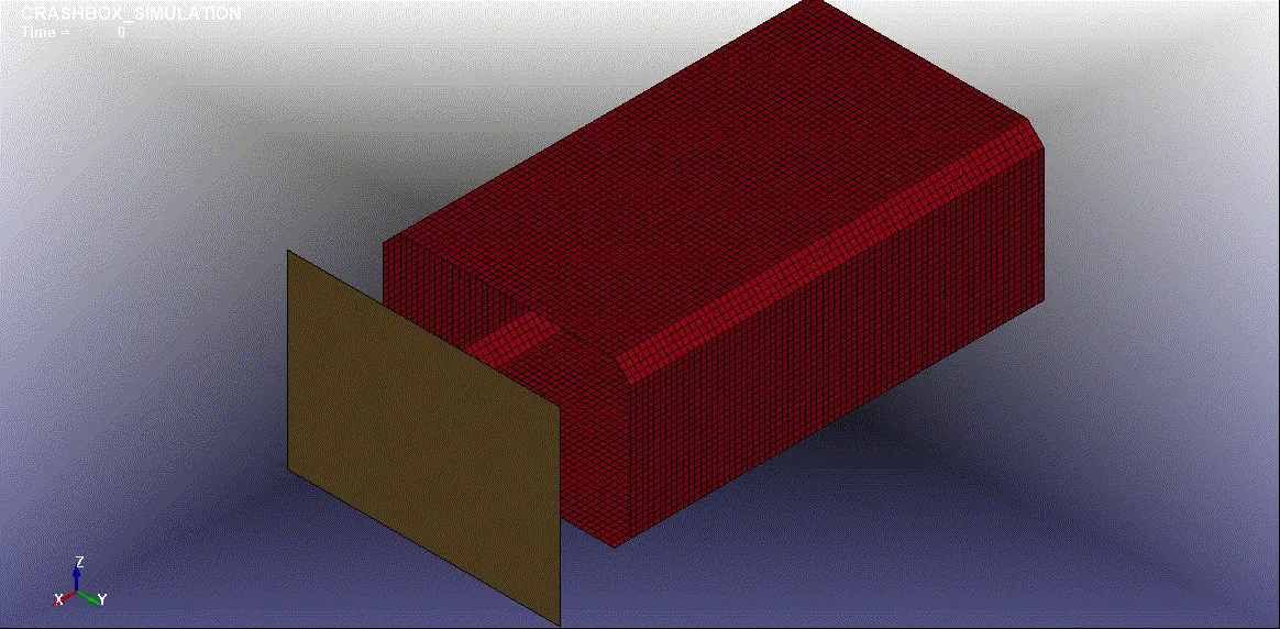
GIVEM MODEL:
PROCEDURE:
Step 1: Import the model File_Open_Ls-Dyna Keyword file and select the file (New_crash_box.k)
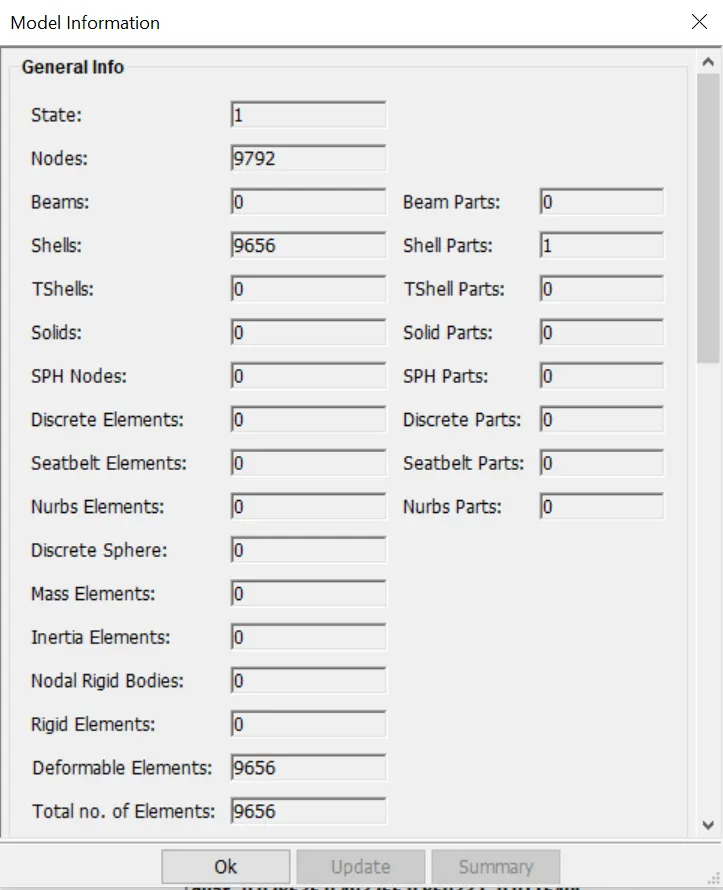
Model has given with only mesh and we have to preprocess it to get the result
MATERIAL:
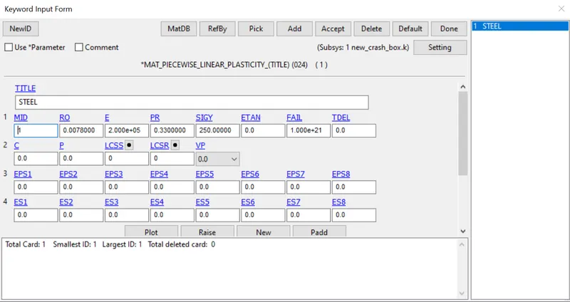
In keyword manager go to material and select *MAT_PIECEWISE_LINEAR_PLASTICITY and assign the value as shown below:
SECTION:
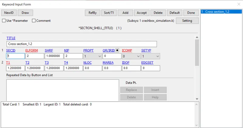
Go to section_shell and create a shell section for 1.2mm thickness as shown below:
PART:
Created material and section has to be assigned to the part
Then go to create Entity_Set data_Create node set for the part present in the model.This has to be create for defining velocity and cross- section
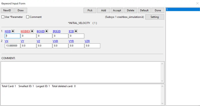
Now go to keyword manager_Initial Velocity and select the nodes set ID.Enter the value of Velocity in gm-mm-ms
Given 50KMPH converting to gm-mm-ms is 13.889mm/ms
INITIAL-VELOCITY:
RIGIDWALL:
Creating Rigidwall by going to Create Entity_Rigidwall=> type:planar=> select the edge node and define the rigid wall. Select Translate option and translate the wall from 50mm to the Crash box
CONTACT:
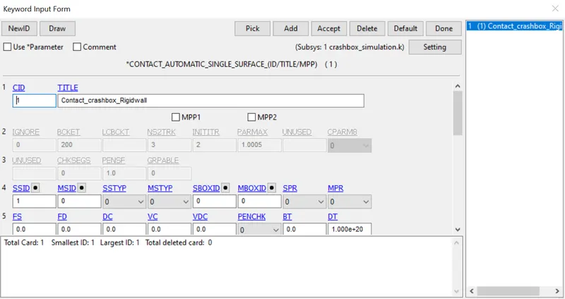
Create a contact interface using the option Automatic_Single_Surface, select the crash box node set as a slave set nodes
CONTROL:
TERMINATION:
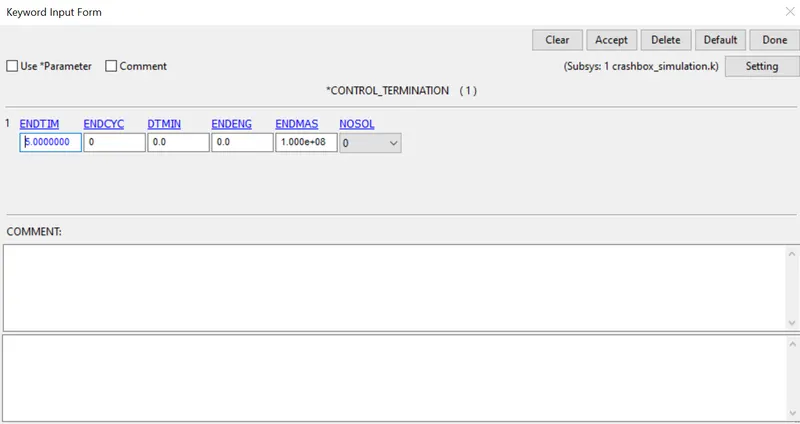
Define a termination card with a run time of 5 ms
ENERGY:
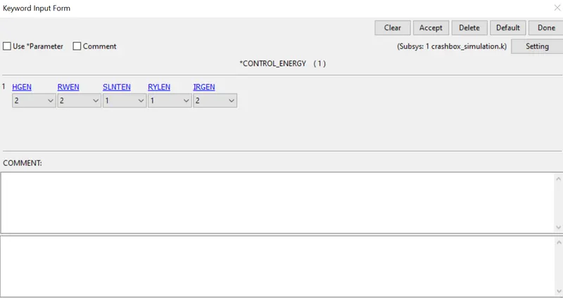
Go to keyword manager_Control_energy and assign Hourglass energy as 2 so it is computed and included in the energy balance
DATABASE:
CROSS SECTION PLANE:
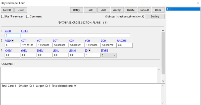
Go to create Entity_Database_Cross section, select 3node and apply the cross section plane at mid area
ASCII:
Choose=>ELOUT,MATSUM,GLSTAT,SLEOUT,SECFORC,NODOUT and enter dt value as 0.1 to define a necessary output files.
D3PLOT:
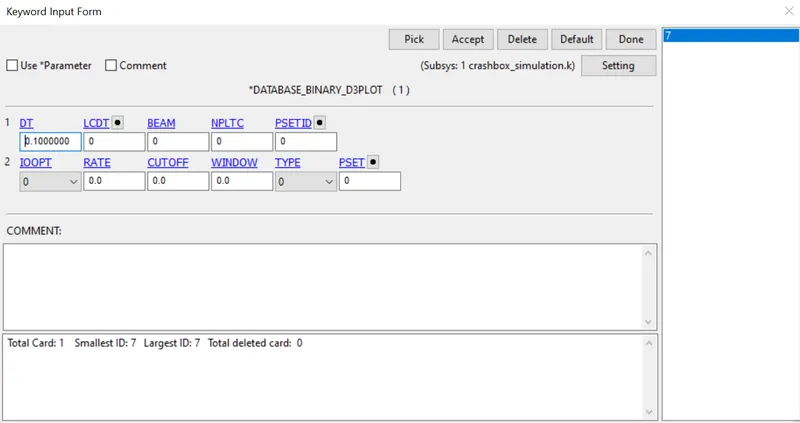
Binary file as D3plot is a Database for complete output states
DT as 0.1
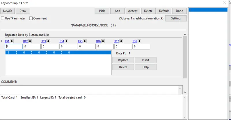
History node as been created so that acceleration plot of a node in the middle of the crashbox will resulted
check the model by going to Model Checking in application save the model in .k file and run the simulation
RESULT:
Animation of the final simulation:
MAXIMUM DIRECTIONAL STRESS AND STRAIN ALONG THE LENGTH
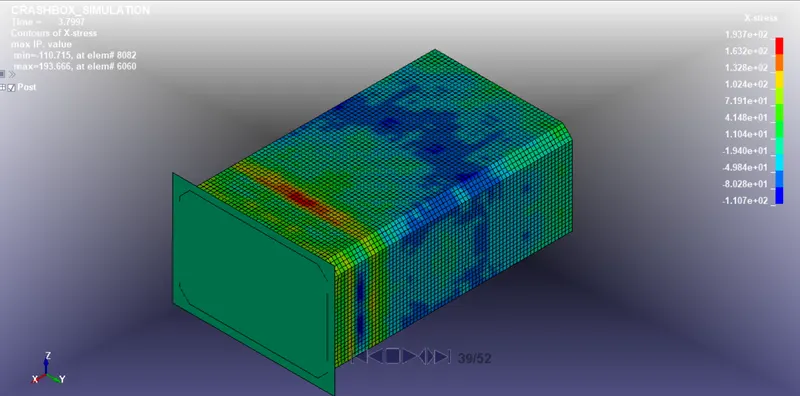
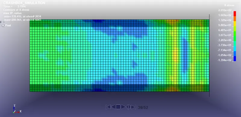
X Stress:
1.2mm Thickness:
1.5mm Thickness:
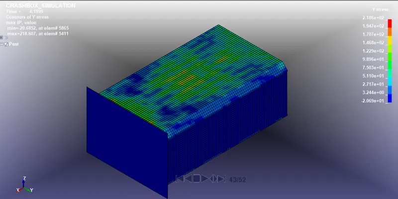
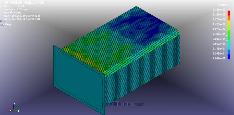
Y Stress:
1.2mm Thickness:
1.5mm Thickness:
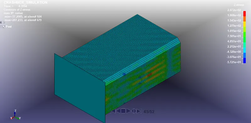
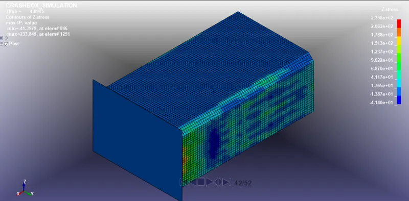
Z Stress:
1.2mm Thickness:
1.5mm Thickness:
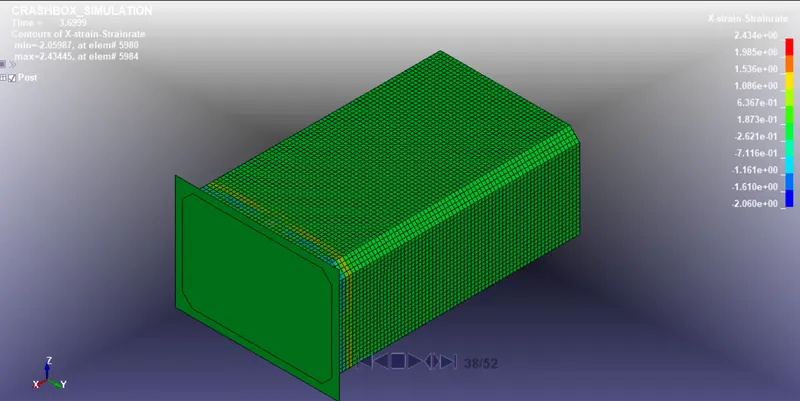
X Strain:
1.2mm Thickness:
1.5mm Thickness:
Y Strain:
1.2mm Thickness:
1.5mm Thickness:
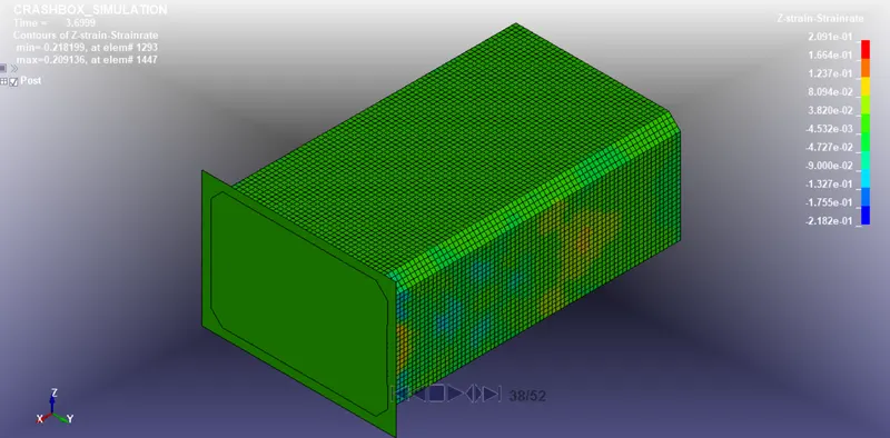
Z Strain:
1.2mm Thickness:
1.5mm Thickness:
CROSS-SECTIONAL FORCE:
1.2mm Thickness:
1.5mm Thickness:
ACCELARATION PLOT OF NODE:
1.2mm Thickness:
1.5mm Thickness:
ENERGY:
1.2mm Thickness:
1.5mm Thickness:
Comparing stress/strain plots of 1.2/1.5mm crashboxes:
|
MAX DIRECTIONAL STRESS/STRAIN
|
1.2MM THICKNESS
|
1.5MM THICKNESS
|
|
X STRESS
|
193.66 MPA
|
200.96 MPA
|
|
Y STRESS
|
218.60 MPA
|
246.75 MPA
|
|
Z STRESS
|
207.23 MPA
|
233.84 MPA
|
|
X STRAIN
|
2.43
|
2.03
|
|
Y STRAIN
|
0.35
|
0.91
|
|
Z STRAIN
|
0.27
|
0.20
|
While comparing both the result of stress/strain with the thickness 1.2mm and 1.5mm, X directional stress is more in 1.5mm Crash box because the velocity will decrease the acceleration and has more stress.
CONCLUSION:
Hence we have got the Directional Stresses and strains and also we have plotted the graph for Cross-sectional force generated in the middle of the crashbox,Acceleration plot of a node in the midplane and Plot of all energies (total, internal, kinetic, hourglass, sliding).