Week - 4 - Crash Box Simulation
Crash Box
Objective
To simulate a crash test on the given simple crash box component
Conditions
- Material for the crash box is steel. The simulation needs to be started using elastic material to verify its correctness and later a nonlinear material card data will be provided. The thickness of the crash box is 1.2mm.
- Initial velocity for the crash box should be around 50 kmph
- The units system to be used is gm-mm-ms
- The simulation should satisfy either of the two situations - (1) It crashes on the rigid wall and rebounds completely or (2) it buckles and folds in the axial direction to come in self-contact.
- Once the simulation is completed and results, as asked for below, is collected, run another simulation by increasing the thickness of the crash box from 1.2 to 1.5mm.
Deliverables:
- Input .k file and output files (d3plot, glstat, sleout, rcforc)
- Animation of the final simulation
- Cross-sectional force generated in the middle of the crash box (along its length)
- Acceleration plot of a node in the middle of the crash box (along its length)
- Maximum directional stress and strain along the length of the crash box (X strain, Y strain etc)
- Plot of all energies (total, internal, kinetic, hourglass, sliding)
- Compare the accelerations and stress/strain plots of 1.2/1.5mm crash boxes.
Theory
A crash box is a high energy-absorbing structure that crashes on the application of loads and reduces the impact on other components nearby. A full-fledges crash box is a highly sophisticated design but in this case, we will go with a rectangular channel which can be thought of as the most simple crash box.
Procedure
- After Importing the keyword file, we can start by applying the boundary conditions
Contacts
- Define the self contact using Automatic Single Surface Keyword
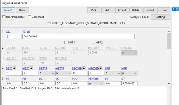
The slave nodes include all the nodes of the crash box.
Rigid wall
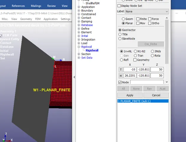
- A rigid wall can be created on either side of the crash box.
- Care should be taken that the normal of the rigid wall is opposite to that of the crash box
- Create the rigid wall using the create entity option
Constraining Elements and Adding Mass
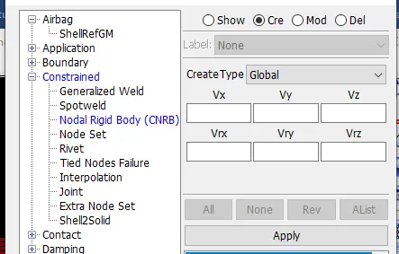
- Create a Nodal Rigid body connection on the opposite side of the box using the create entity option.
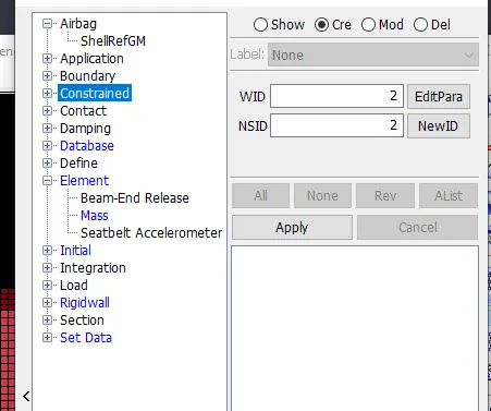
- Similarly, Add a mass of 200kg to the created Master node.
Initial Velocity
- The Initial velocity, given as 50Kmph is converted into 13.88mm/ms
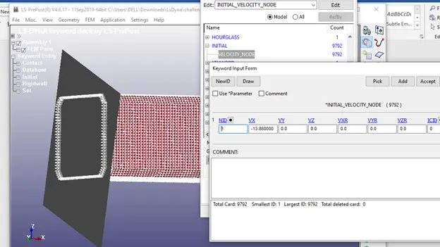
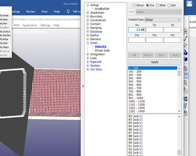
- Apply this velocity to the x-axis to all the elements using the create entity option
Material
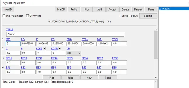
- In the keyword manager, create a mat001 elastic and mat024 Linear Plastic material card and add the appropriate values in the proper units
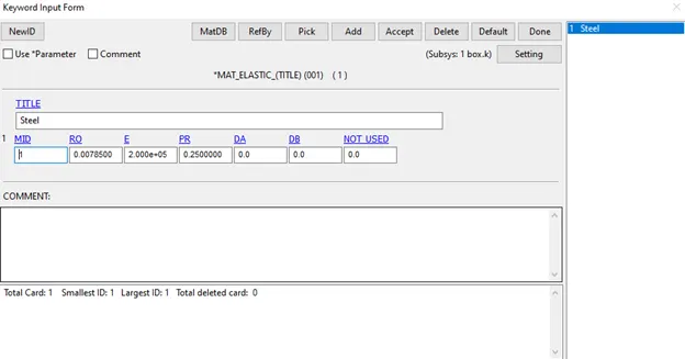
- We are approximating the Etan Value to 1% of Youngs Modulus.
Section
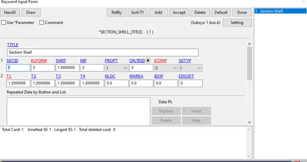
- Create a section shell keyword using the keyword manager and assign a thickness of 1.2mm.
we will change this value to 1.5mm for the second case - We will be using the Belytschko-Tsay (default) element formulation.
- Other than that we will be using the default values given.
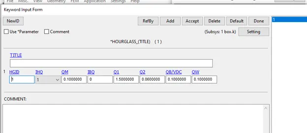
Hourglass
- Create an hourglass keyword as shown.
Creating Section and Node
- In create Entity Option, under Database
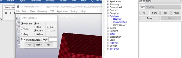
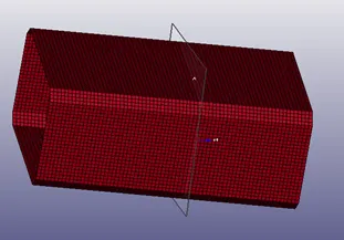
- Create a history on a node on the top portion of the crash box and a cross-section in the middle.
Output Files
- In the database, create the d3plot and Ascii keywords
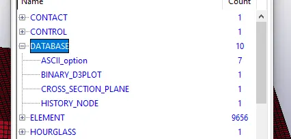
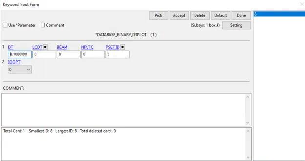
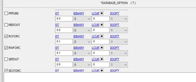
- In Ascii,enable Glstat,Matsum,Nodout,Rcforc,Rwforc,SecForc and Sleout
Control
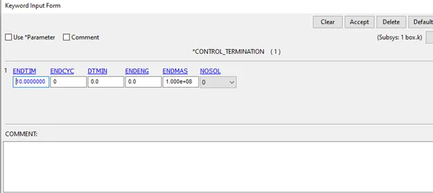
- Create a Control Termination Keyword
Check the keywords using the model checker for errors
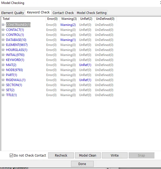
No errors only warnings and unref.
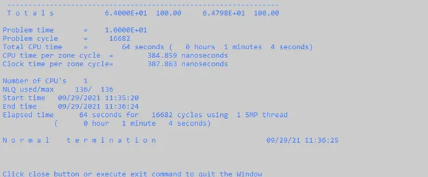
After this run the simulation using the ls Dyna solver
Make sure that the folder has no spaces and the termination is normal termination.
Post Processing
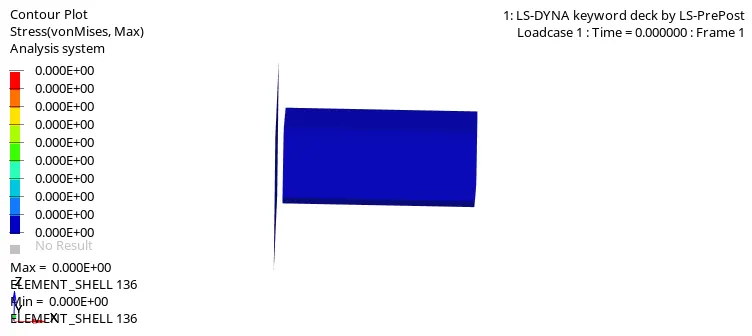
On looking at the animation of the model without the constrained element and added mass, it can be seen that deformation does not take place.
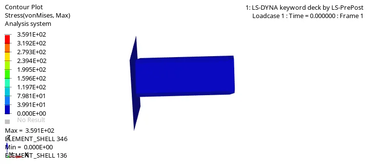
However, after constraining and adding a mass, deformation can be observed.
On comparing this to the crash box with 1.5mm thickness.
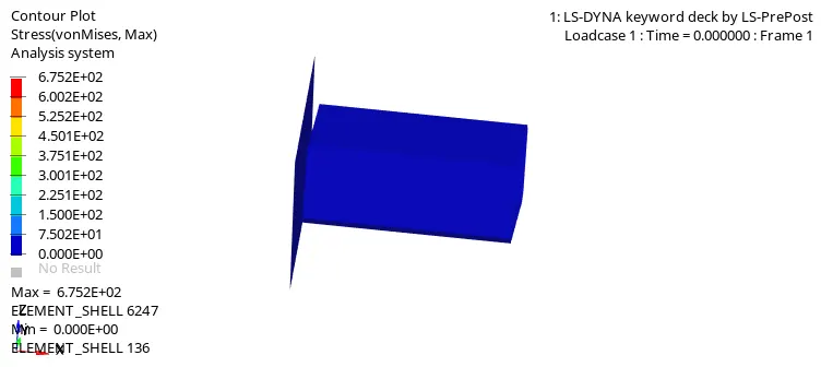
It can be seen clearly that the pattern of deformation is different in the 2 cases.
This is because of the Centre of Gravity varying in the 2 components, leading to deformation occurring at different locations.
The case using the elastic material has a completely different result.
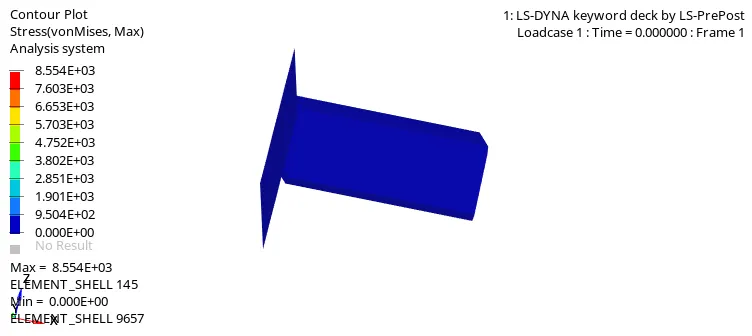
In this, the crash box bounces away from the rigid wall after impact.
This elastic behaviour is unrealistic should not be considered for analysis.
Crash Box 1.2 mm shell thickness
Energy Graphs
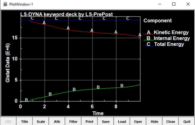
In the beginning, Kinetic Energy is high due to the initial velocity, as impact happens it gets converted to Internal Energy.
It is higher than Internal energy as there is a lot of vibration of elements due to deformation.
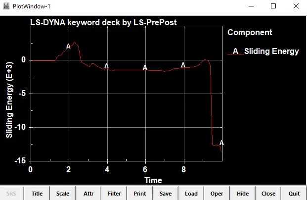
The contact energy or sliding energy is the energy spent to resist the penetration of elements. After impact, since there is no other contact defined the crash box bounces up explaining the negative dip in contact energy.
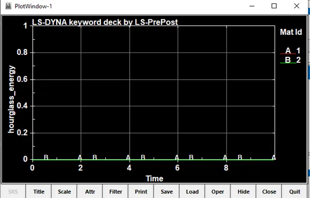
Hourglass energy is 0 due to the use of the hourglass keyword.
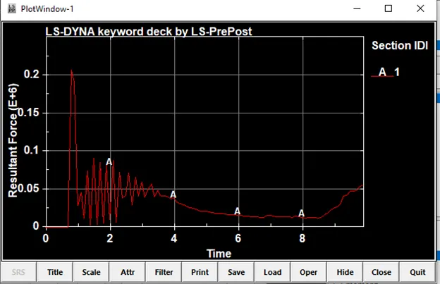
There is a high spike in sectional force at the beginning due to the impact.
Further spikes can be attributed to the deformation of elements.
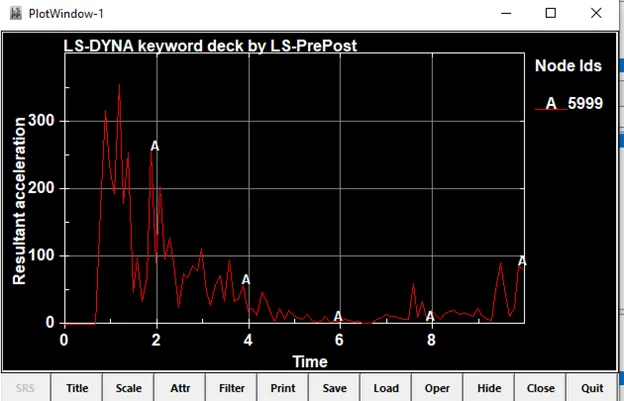
The acceleration reaches its peak during the initial impact.
It varies rapidly during the simulation indicating high vibration of elements.
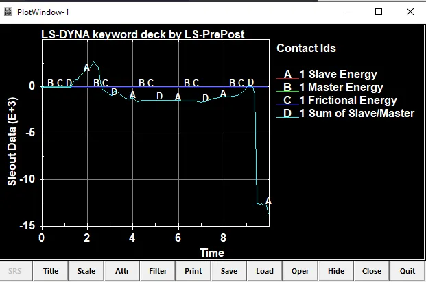
In LS-DYNA, contact energies are reported in the SLEOUT file.
Therein, four different values can be found:
- slave energy (SE)
- master energy (ME)
- frictional energy (FE)
- sum of slave/master energy (SoSM) = SE + ME
The 'Sliding Energy' included in GLSTAT equals the sum of "sum of slave/master (SoSM)" from SLEOUT.
Crash box 1.5mm Shell Thickness
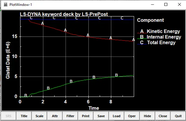
In the beginning, Kinetic Energy is high due to the initial velocity, as impact happens it gets converted to Internal Energy.
It is higher than Internal energy as there is a lot of vibration of elements due to deformation.
It can be seen that the Kinetic Energy is lower compared to the previous case, indicating higher energy absorption
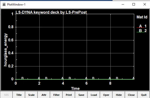
Hourglass energy is 0 due to the use of the hourglass keyword.
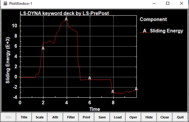
The contact energy or sliding energy is the energy spent to resist the penetration of elements. After impact, since there is no other contact defined the crash box bounces up explaining the negative dip in contact energy.
Compared to the 1.2 mm thickness, the contact energy is significantly higher due to the higher energy absorption of elements.
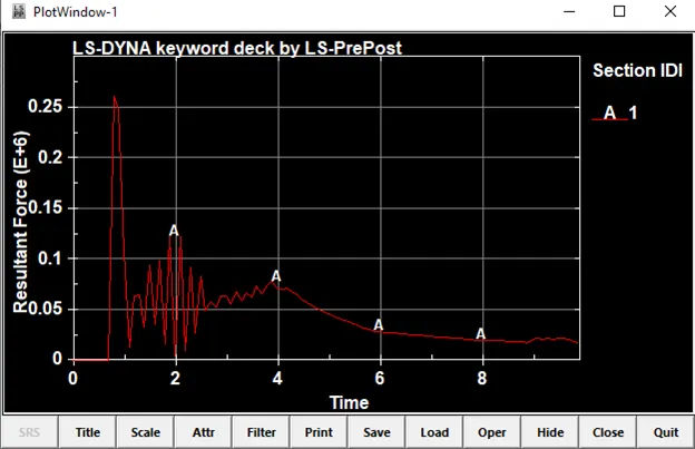
There is a high spike in sectional force at the beginning, in both positive and negative directions, due to the impact.
Further spikes can be attributed to the deformation of elements, after which it tends to zero indicating complete deformation.
The cross-sectional forces are higher in these cases indicating higher stability
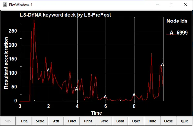
The acceleration reaches its peak during the initial impact.
It varies rapidly during the simulation indicating high vibration of elements
The peak is higher in comparison to the 1.2mm thickness further indicating higher energy absorption.
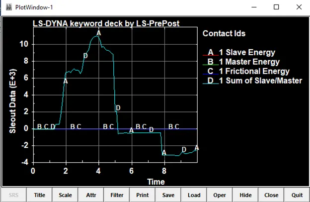
In LS-DYNA, contact energies are reported in the SLEout file.
Therein, four different values can be found:
- slave energy (SE)
- master energy (ME)
- frictional energy (FE)
- sum of slave/master energy (SoSM) = SE + ME
The 'Sliding Energy' included in GLSTAT equals the sum of "sum of slave/master (SoSM)" from SLEOUT.
Learning Outcomes
- Tangent Modulus and Its Significance
- Setting up a crashbox analysis in Ls Dyna
- Impact of Thickness on crash box stability
Conclusion
Thin-walled structures like crash boxes may be used as energy absorption members in automotive chassis. There have been many studies addressing the behaviors of energy absorption members on frontal crash. These researches have attempted to predict the energy absorption and maximum impact load in shell structures. The energy absorption and maximum impact load depend on many parameters including boundary condition, history of plastic deformation during metalworking, geometry; and material and impact energy (i.e. mass and velocity of the striker)
The effect of thickness of the crashbox on its energy absorption capabilities have been studied by comparing the energy ,sectional and acceleration Graphs of a 1.5mm and 1.2mm thickness crash box.It was observed that the 1.5mm thickness crash box had better energy absorption capacity.