Week - 4 - Crash Box Simulation
AIM; To simulate the crash test for a crash box with an different shell thickness and compare the plots of the crash boxes.
PROCEDURE
- Import the model
- Select the model and set the keyword manager for simulation of an crash box.
- To analysis the crash box, we have to create the Rwall,velocity, sections, node list, part, control and data base etc.
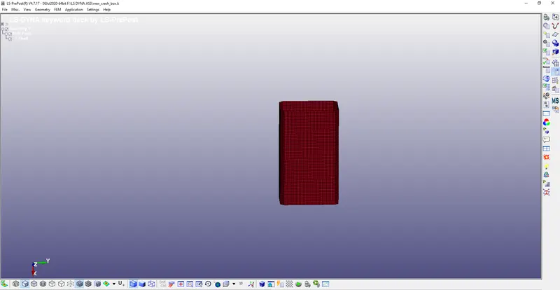
- creating the Rigid wall
create entity>rwall>select planer
- First, we need to create a rigid wall.
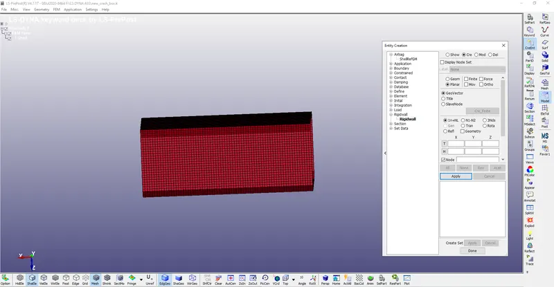
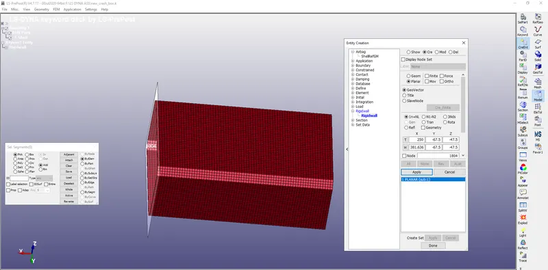
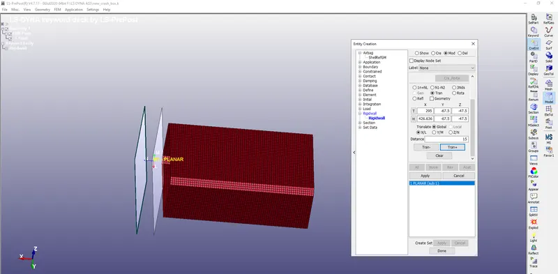
- To create the rigid wall, we need to go to entity creation and select rigid wall select planar and pick node and apply on it, it will shows the rigid wall and use modify option to translate the Rwall.
SECTION
Shell
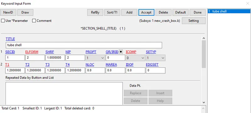
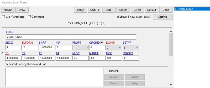
Section is used to create the properties of elements, element formulations and thickness of the particular model.
Here we take thickness of shell is 1.2mm and 1.5mm propertites.
Material
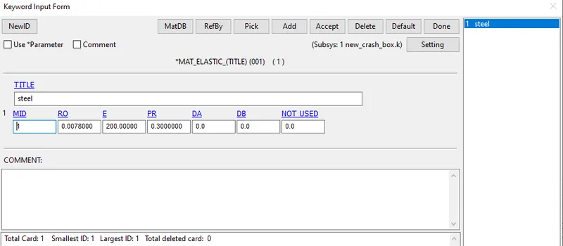
- For assigning the material property we need to go to keyword manager and select all.
- And then we need to go to MAT and select concerning material.
- Assigning the steel material propertites to the crash box .
PART
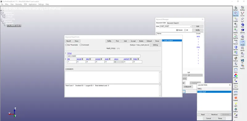
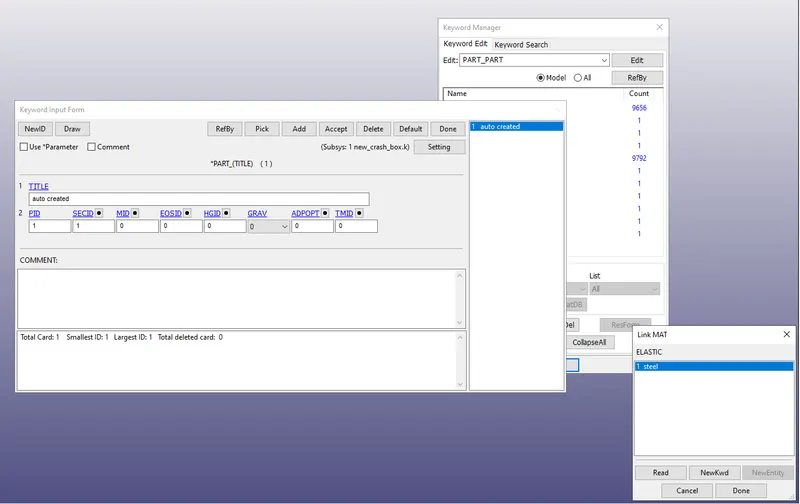
- To define a part we must have nodes, elements, sections and materials.
- Assign the section and material to the part IDs.
CONTACT;
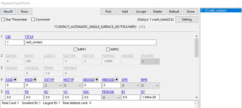
- For this model, we have to give the Automatic_ single_surface contact to the crash box.
- go to keyword entity select all>click on Automatic_ single_surface and set the slave node id as crash box part id and accept and apply to it.
Creating the velocity.
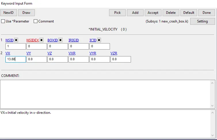
- After that, we need to give the velocity of 13.88 mm/ms
- To give velocity we need go to all to select the initial and select velocity.
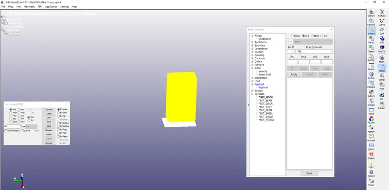
- before that we create node list and pick nodes on the crash box.
- Assign the node list to the NSID and set the velocity in an particular direction.
CONTROL TERIMINATION
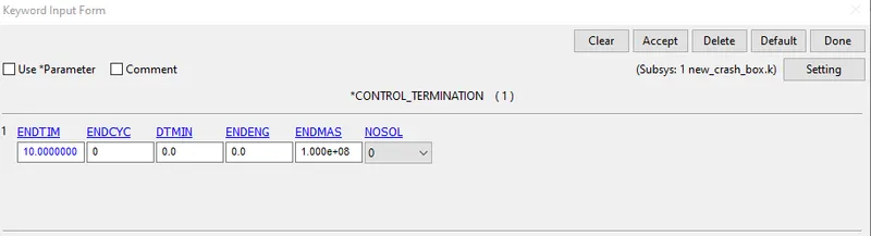
- Control cards is used to set the Termination time for an simulation model.
- To set control card, Model >Keyword manager > control >Termination command is used. The simulation time is set to 10ms
- Used for creating the output results for the model.
DATABASE
BINARY
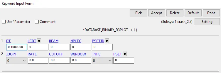
- BinaryD3plot
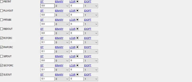
- Keyword Manager > Database >Binary D3plot >DT 0.1. It prints the Output file at each 0.1ms. The D3PLOT card gives animation view get the results in the post-processing data after the simulation.
ASCII
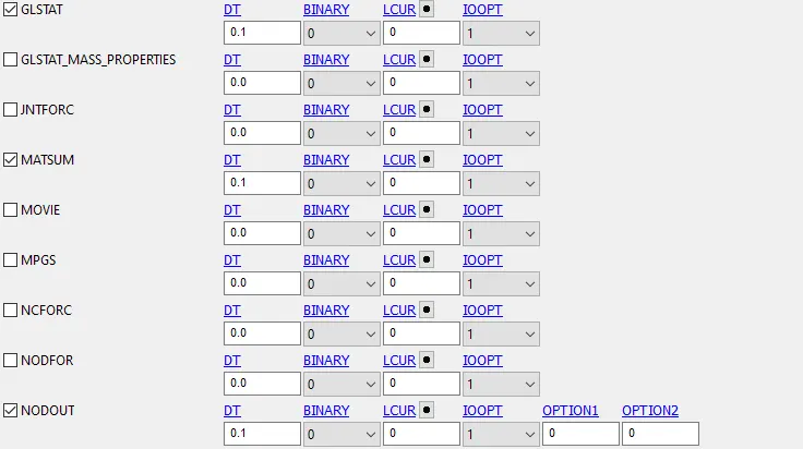
GLSTAT: used to define all the global energies.
MATSUM: used to define the material energies.
SLEOUT:record energies due to sliding contact.
SECFORCE: used to define the cross sectional forces.
NODOUT: used to define the nodal displacements.
CROSS SECTION;
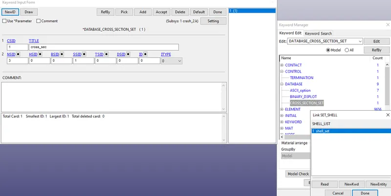
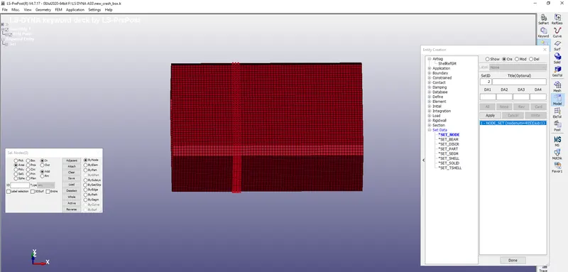
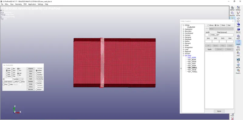
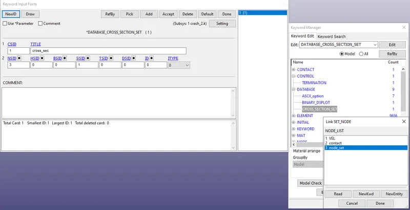
- For creating the section forces, we have to create a specific node and shell list which defines the desired section of component is necessary. The selection of nodes and shell lists is done by picking each node and element through Creating Entity>Set Data>set node and set shell list.
- Assign the nsid and ssid to the cross section.
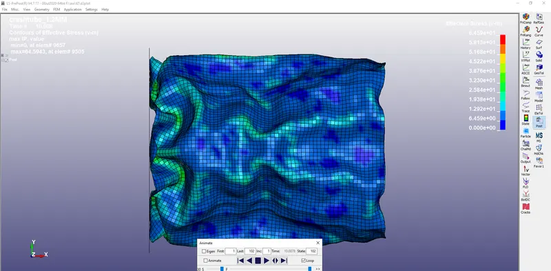
max vonmoises stresses is generated at 6.459e+01 or 64n/mm^2 at element 9505.
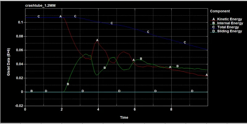
glast
from the graph the upto 2ms there is no action of the tube, later kinetic energy starts increasing and suddenly reduces due to increasing of the internal energy.
MATSUM
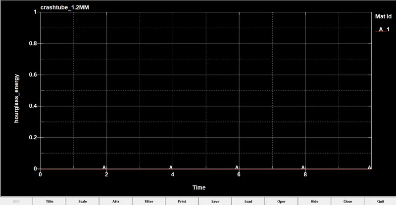
hour glass energy is zero throught the process.
RWALL
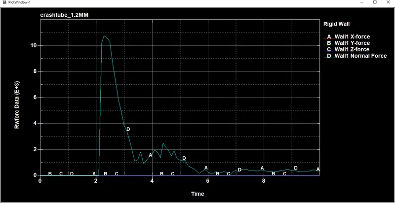
In the graph, the rwall forces will increases peak at 2.1ms and slowly decreases after the contact was disconnected to the wall.
SLOUT
CROSS SECTION
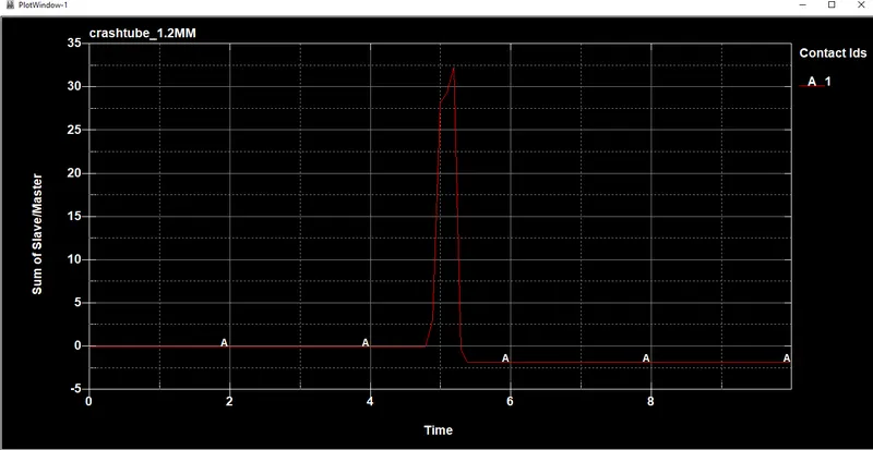
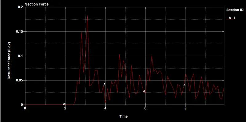
- From this graph, we can understand that the contact between the rigid wall and crash box starts at the 2.2ms.
- The normal resultant forces increases at 3.1ms and slowly the forces got decreased after crash tube get contactless to the rwall.
1.5mm thick
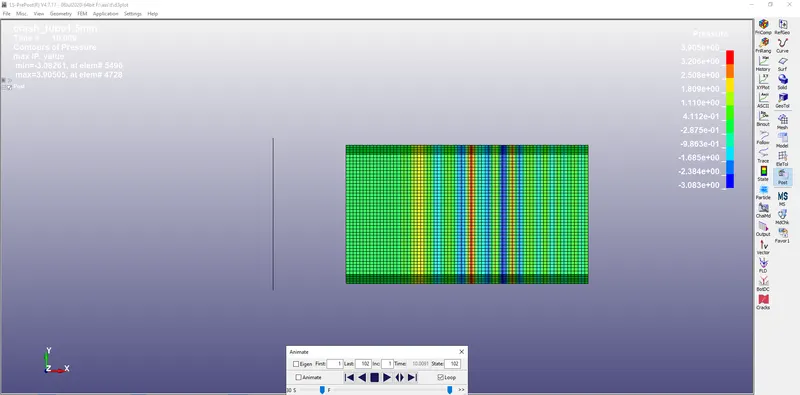
The max vonmoises stresses is 39n/mm^2 attained at the element of 4728.
glstat
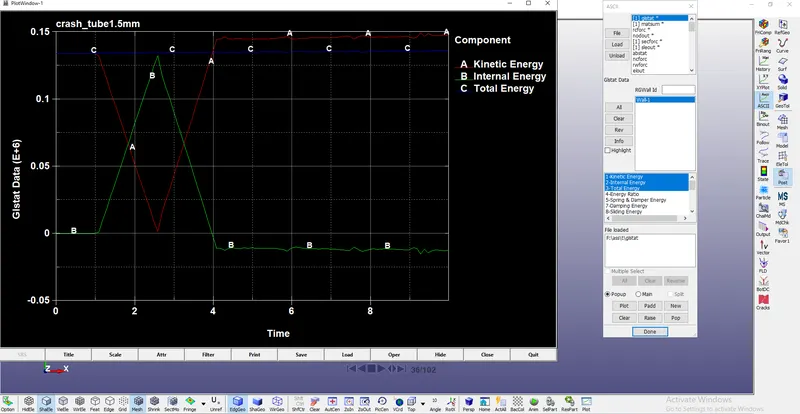
- In this the kinetic energy is decreases with increasing of the internal energy at the 1ms.
- The total energy is remaining constant throught the process.
SLEOUT
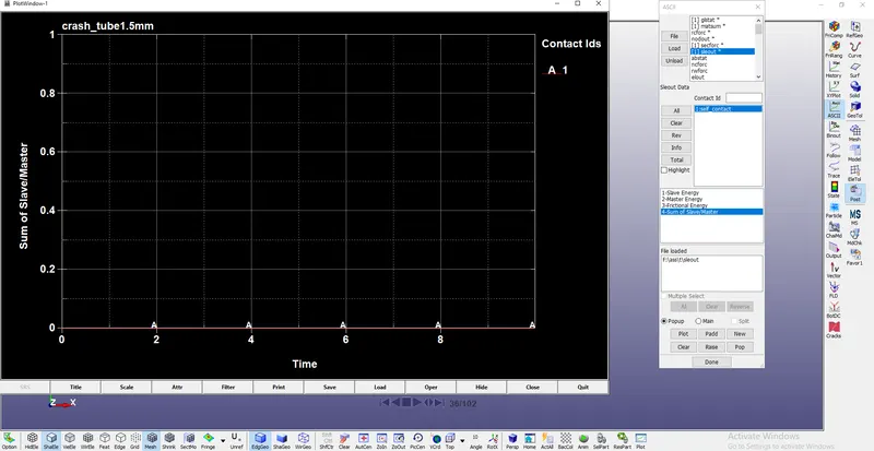
compare to the 1.2mm thickness sliding energies are constant and there is no fluctations produced in it.
MATSUM
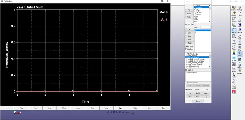
Hourglass
RWFORCE
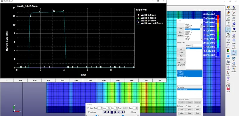
The Rwall starts at the 1ms and increases to the 13kn force and it remains constant up to the 4ms and when there is contact is no contat in between the Rwall and Crash box it will decreases the force slowly.
CROSS SECTIONAL
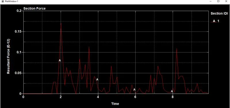
The cross sectional forces are constant at starting and increases its force at peaks in 2ms.
OBSERVATIONS AND RESULT;
- we can see that as thickness is increased then the internal energy is increased and there is a decrease in the kinetic energy.
- The force for the component has high for 1.2mm thickness and it buckles a lot compare the thickness having 1.5mm crash tube.
- More amount of sliding energies are recorded compare to the 1.5mm thickness crash box.
- The stress developed in the 1.2mm crash box is more than 1.5mm box.
- we have simulated the crash box with an varing different thickness.
links
crash_box1.2
https://drive.google.com/drive/folders/10ve272xJ-xwbKKpR7f_Maq4r1SiXJbJI?usp=sharing
crash_box1.5
https://drive.google.com/drive/folders/1q3PVvViTVMW2TB_D-ozRJMJ5g5q-0j2Q?usp=sharing