Week - 4 - Crash Box Simulation
AIM: To simulate the crash test for the crash box with given parameters and creating the rigid wall.
Procedure:
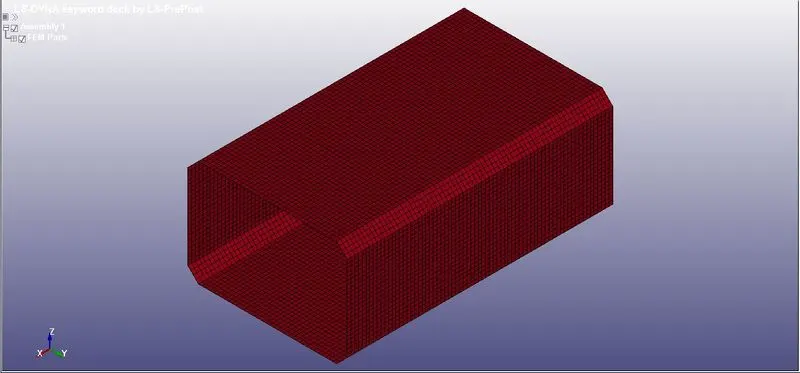
- This is the crash box, now we have to create the RIGIDWALL for this.
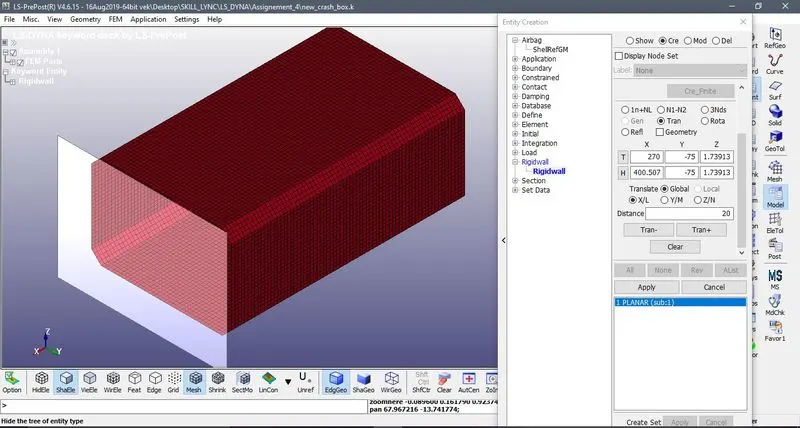
- To create the RIGIDWALL go to KEYWORD>CREATE ENTITY>RIGIDWALL
- We will select the planer RIGIDWALL for this.
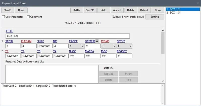
- Now we will create a section of the box for this go to the MODEL>KEYWORD>SECTION and then give the thickness.
- Create two shell cards with thickness 1.2mm and 1.5mm.
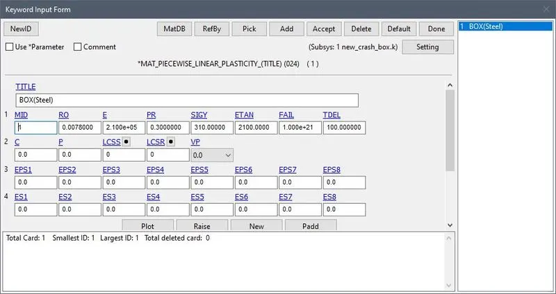
- Now we have to assign the material to the box.
- For this go to MODEL>KEYWORD>MAT>024_MAT_PIECEWISE_LINEAR_PLASTICITY
- We are using the unit system as gm-mm-ms.
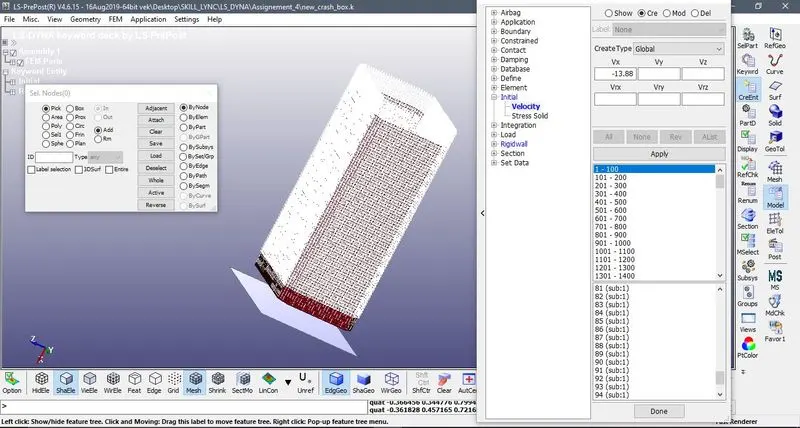
- Now assign the initial velocity to the box. i.e. 50kmph=13.88mm/ms
- For that go to the MODEL>CreEn>INTIAL>VELOCITY3
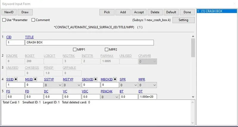
- Now we will create a contact between the surface.
- For that go to the MODEL>KEYWORD>CONTACT>AUTOMATIC_SINGLE_SURFACE
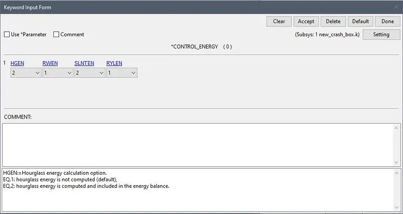
- Now we requrired output of different types of energies. For that go to MODEL>KEYWORD>CONTROL>ENERGY
- This will give us Hourglass and Sliding energy.
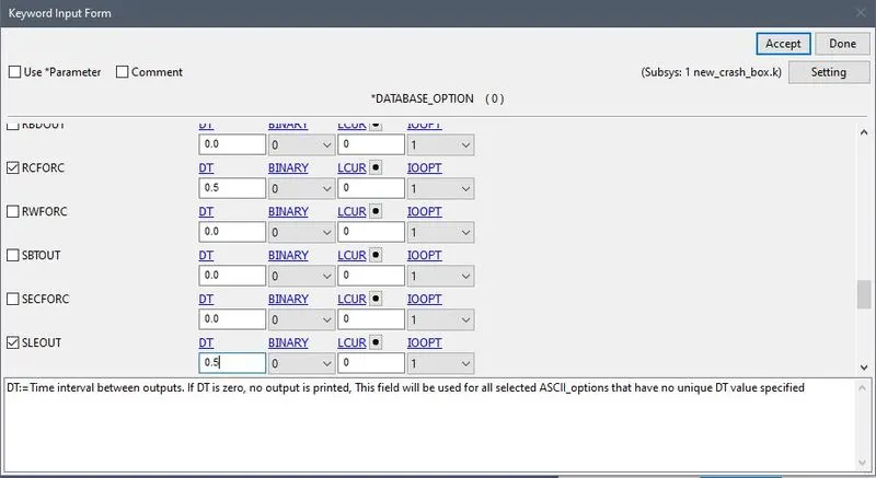
- Now go to MODEL>KEYWRD>DATABSE>ASCII_OPTION
- And select glstat,sleout,rcforc to get outputs.
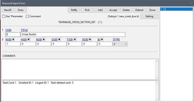
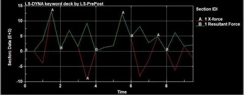
- Now for the Cross-sectional force we have to first create a section for that go to MODEL>KEYWRD>DATABASE>CROSS_SECTION_SET
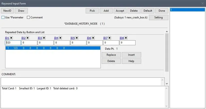
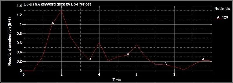
- For the plotting the accelaration graph we will select the node fo that go to the MODEL>KEYWRD>DATABASE>DATABASE_HISTORY_NODE
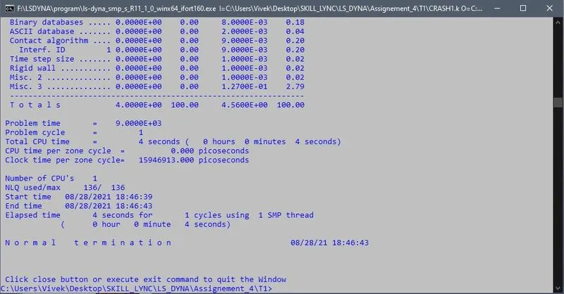
- Now we will save the .k file and check for the simulation.
- First we will select the section of thickness 1.2mm and after that section of 1.5mm.
- And then we will compare the data for both thickness.
OUTPUT GRAPHS:
With Thickness 1.2 mm
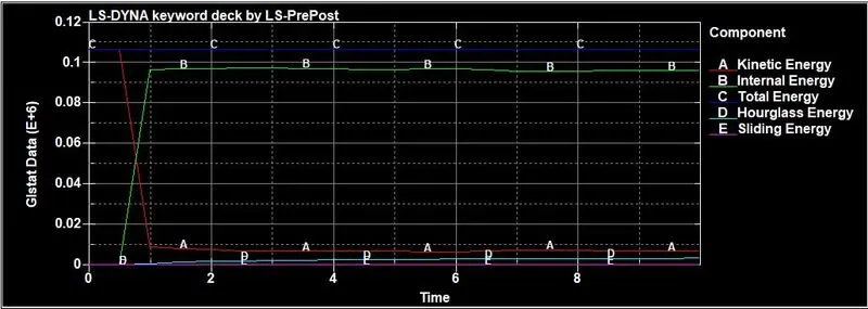
1. ENERGY
2. ACCELARATION at NODE 123
3. CROSS SECTIONAL FORCE
D3PLOT
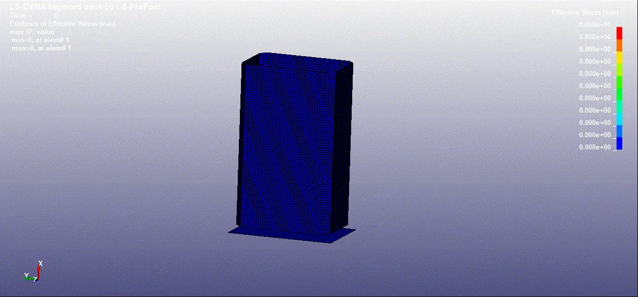
1. VON MISES
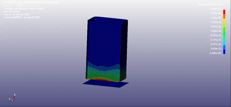
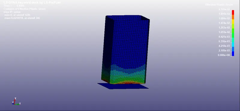
2. PLASTIC STRAIN
WITH THICKNESS 1.5 mm
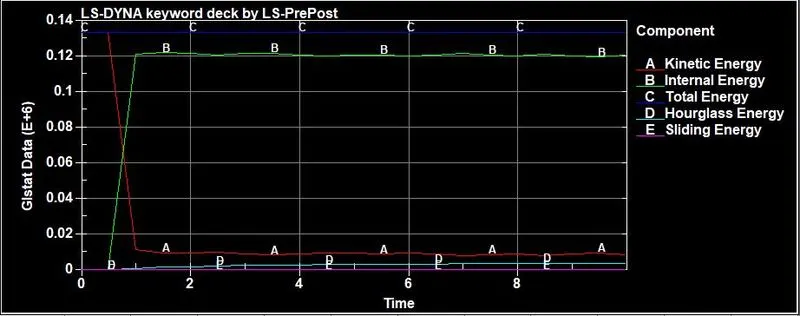
1. ENERGY
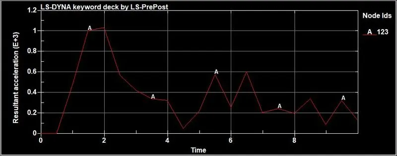
2. ACCELARATION at NODE 123
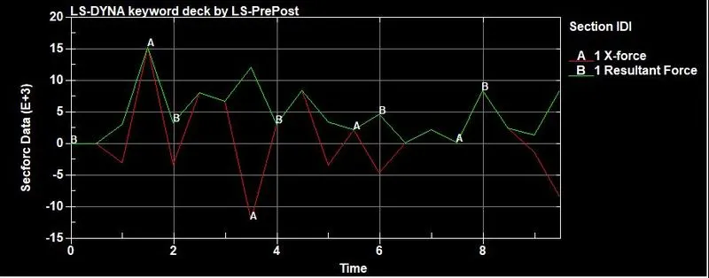
3. CROSS SECTIONAL FORCE
D3PLOT
1. VON MISES
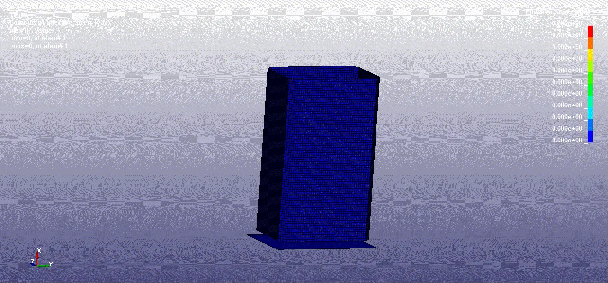
2. PLASTIC STRAIN
OBSERVATION
1. ENERGY
- So the plot has been plotted between for the Kinetic energy , Internal energy , Hourglass energy , Sliding energy.
- Here we can see the Internal energy is higher in the box with thickness 1.5mm than the other box with 1.2mm.
- In both the total energy is constant and the sliding energy is minimum.
2. ACCELARATION
- Here the acclelaration of box with thickness 1.2mm is higher the the box with thickness 1.5mm.
- The node in box 2 has more fluctuation that the first box.
3. SECTIONAL FORCE
- The sectional force in box with shell 1.5mm is more than the box with the 1.2mm
OUTCOMES:
- Able to plot sectional force.
- Got knoledge about RIGIDWALL
- Able to contruct RIGIDWALL
- Able to give acclelaration to the node.
RESULTS
- The RIGIDWALL is constructed.
- The simulation is done on the crash box with thickness 1.2 mm and 1.5 mm with the velocity 50kmph.
- The reqiured graphs are plotted as per asked.