Week 4 - CHT Analysis on Exhaust port
Aim :
- To perform a CHT analysis on the Exhaust port in Ansys Fluent.
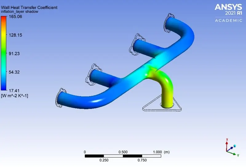
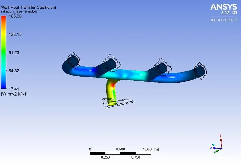
- To calculate the wall heat transfer co-efficient in the exhaust port.
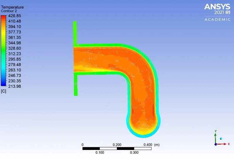
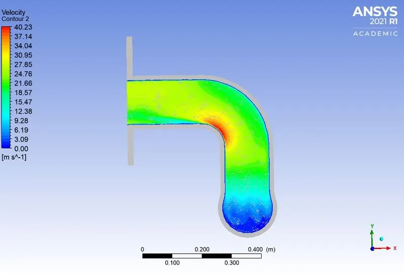
- To show the velocity & temperature contours of the exhaust port.
Conjugate Heat Transfer (CHT) :
Conjugate heat transfer (CHT) allows the simulation of the heat transfer between Solid and Fluid domains by exchanging thermal energy at the interfaces between them. In solids, conduction often dominates whereas, in fluids, convection usually dominates.
An exhaust manifold collects the exhaust gases from multiple cylinders into one pipe. It is attached downstream of the engine and is of major relevance in multi-cylinder engines where there are multiple exhaust streams that have to be collected into a single pipe. When an engine starts its exhaust stroke, the piston moves up the cylinder bore, decreasing the total chamber volume.
When the exhaust valve opens, the high-pressure exhaust gas escapes into the exhaust manifold or header, creating an exhaust pulse comprising three main parts: The high-pressure head is created by the large pressure difference between the exhaust in the combustion chamber and the atmospheric pressure outside of the exhaust system. As the exhaust gases equalize between the combustion chamber and the atmosphere, the difference in pressure decreases and the exhaust velocity decreases.
Backpressure usually refers to the pressure exerted on a moving fluid by obstructions against its direction of flow. Backpressure caused by the exhaust system of an automotive engine has a negative effect on engines' performance as it will restrict the flow rate of the exhaust gasses.
The result would be the engine not being able to expel the spent exhaust gasses fast enough to prevent spent exhaust gasses from contaminating the fresh air/fuel mixture that is drawn into the engine on the next intake stroke. Ultimately, this will result in reduced engine power.
Examples of Conjugate Heat Transfer Analysis :
HVAC, Heat Exchanger, IC Engines, Heat Sink, Boiler & Turbocharger.
The outcome of CHT :
- Wall Heat Transfer Co-efficient.
- Temperature Distribution (contours).
- Heat Transfer rate analysis.
- Identification of localized hot spots or heat sinks in checking against specified requirements.
- Realistic visualization of heat transfer.
- Heat Fluxes.
Exhaust Port Geometry :
Solid Domain :
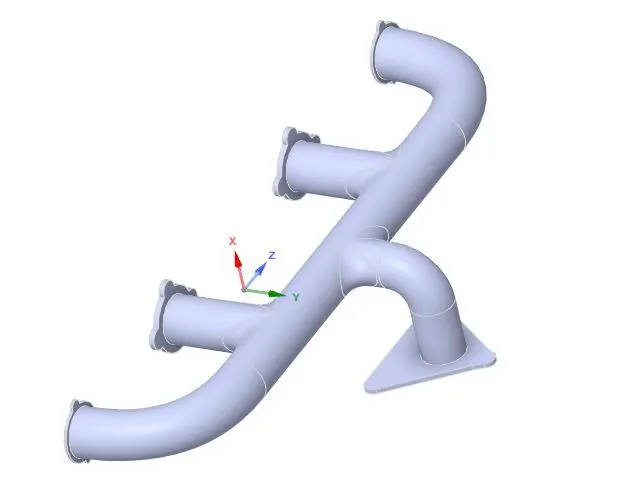
Fluid Domain :
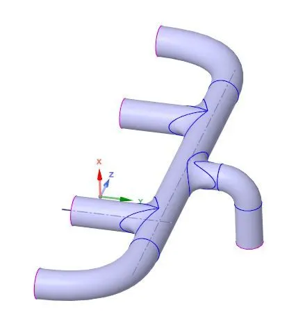
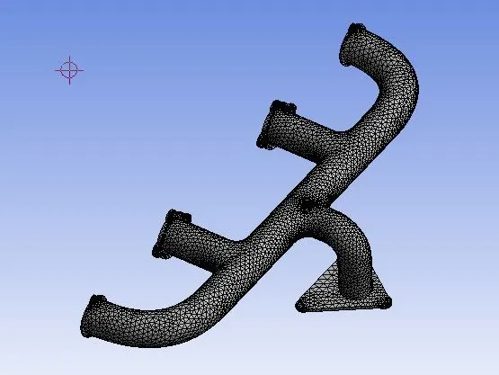
Mesh :
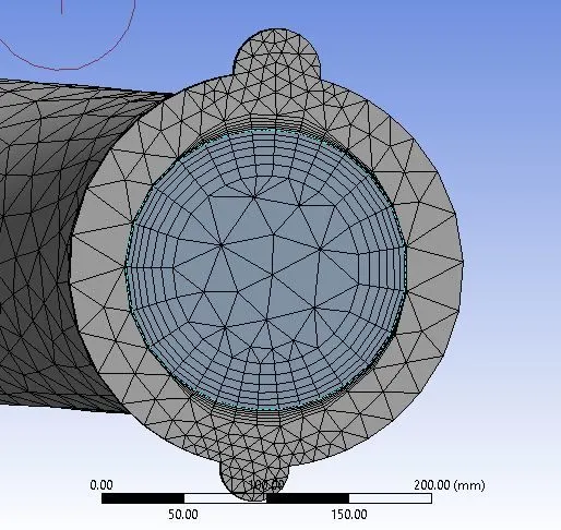
Inflation :
Mesh Quality :
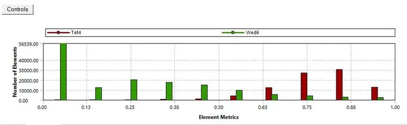
Mesh Statistics :
Number of Elements - 229474
Element Size - 90 mm
Inflation :
Number of layers - 6
Total Thickness - 27.8 mm
Growth rate - 1.2
Named Selections :
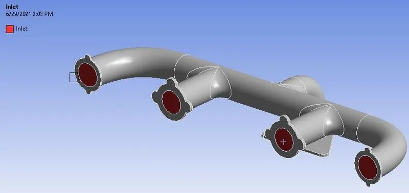
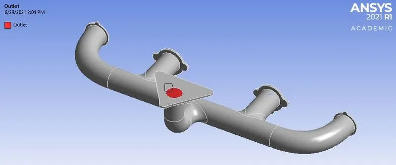
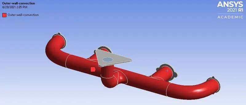
Case (1) :
Solver Settings :
Type - Steady-state, pressure-based solver
Models :
- Energy - on
- Viscous - K-e, Standard wall function
Materials :
- Fluid - Air
- Solid - Aluminium
Boundary Conditions :
Velocity Inlet - 5 m/s, Temperature - 700k
Pressure outlet - 0 pa (gauge pressure)
Convective wall - 20 W/m^2k
Result :
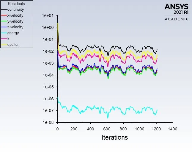
Residuals :
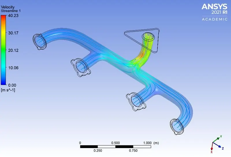
Velocity Streamline :
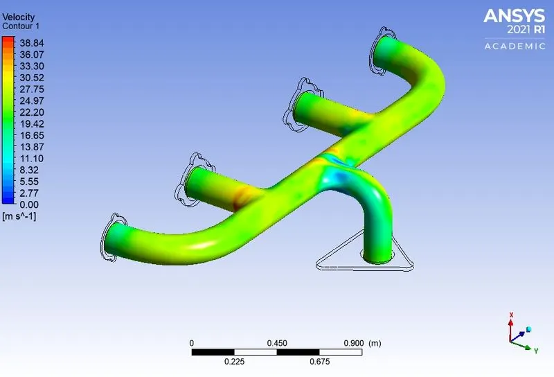
Velocity contour :
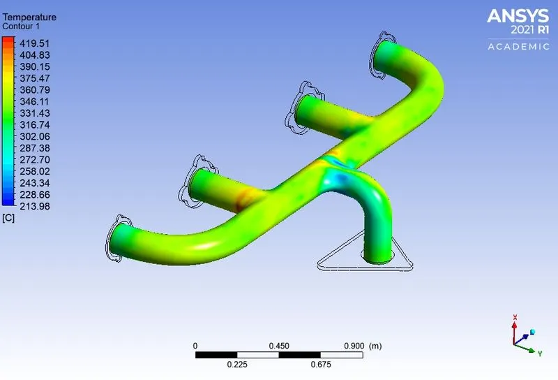
Temperature contour :
Temperature on midplane :
Velocity on midplane :
Wall Heat Transfer co-efficient :
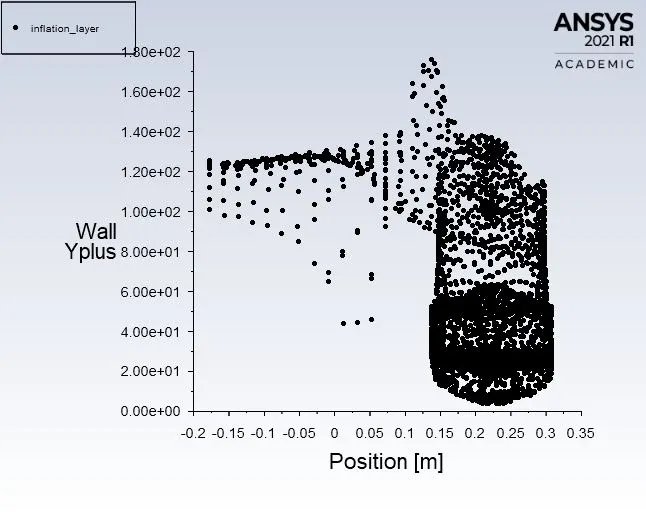
Wall Y plus :
Case (2) :
Mesh :
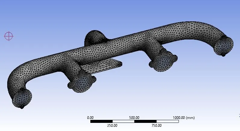
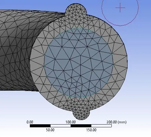
Inflation :
Element Quality :
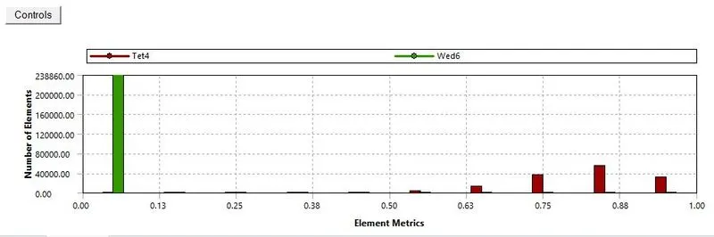
Mesh Statistics :
Number of Elements - 374596
Element Size - 90 mm
Inflation :
Number of layers - 10
Total Thickness - 0.00436 mm
Growth rate - 1.2
Solver Settings :
Type - Steady-state, pressure-based solver
Models :
- Energy - on
- Viscous - K-omega, SST
Materials :
- Fluid - Air
- Solid - Aluminium
Boundary Conditions :
Velocity Inlet - 5 m/s, Temperature - 700k
Pressure outlet - 0 pa (gauge pressure)
Convective wall - 20 W/m^2k
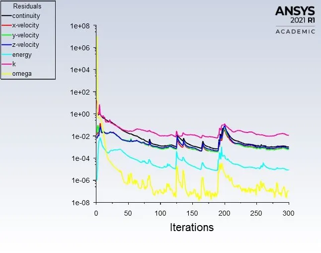
Result :
Residuals :
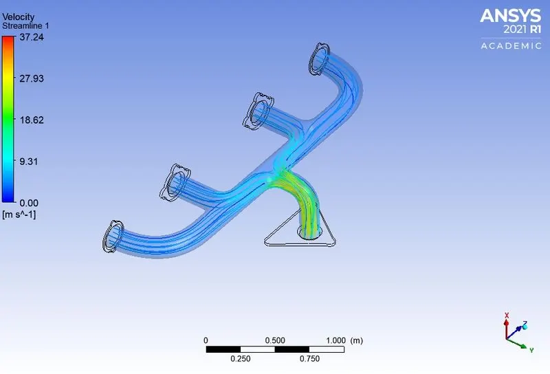
Velocity Streamline :
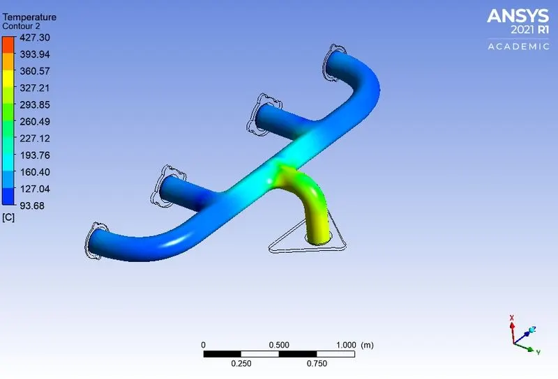
Temperature Contour :
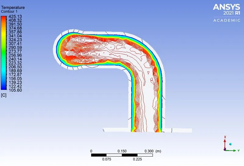
Temperature on midplane :
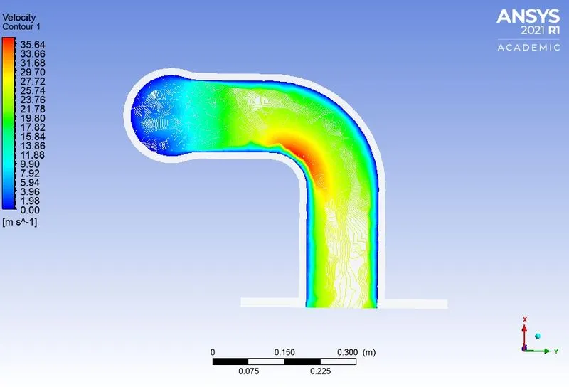
Velocity on midplane :
Wall Heat Transfer co-efficient :
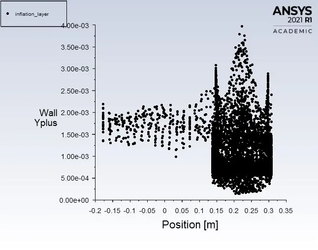
Wall Y plus :
Nusselt Number :
As we know, the Nusselt number is the ratio of heat transfer due to convection to heat transfer due to conduction.
From all of the above streamline figures and velocity contour, it's visible that velocity at the bend is maximum. It is correct as the law of conservation of mass is present. The maximum velocity is presented at the corner due to a bend i.e. sudden change in direction of
the fluid.
Nu =hl/k
When the velocity is maximum, the Reynolds number at that place is also maximum and it cause Reynolds number is directly proportional to the velocity.
Reynolds number is also directly proportional to the Nusselt number which results from high convection rate.
Verify the HTC Predictions from the simulation :
- The calculated value of HTC (heat transfer coefficient) by simulation can be confirmed from experimental data.
- HTC value can be verified by theoretical authentic data.
- By comparing the Nusselt number we can verify HTC.
Factors that affect the accuracy of the prediction :
- Accurate modeling of physics.
- Mesh should be enough refined to capture smooth shedding.
- By performing mesh independent test.
- Mesh should capture geometry (curved faces) precisely.
- Inflation layers.
- Selection of y+ value in range.
- Selection of viscous solver model.
- Material selection.
- The accurate property of material should be mentioned in the problem.
Conclusion :
From the above-obtained result data and post-processed plots we can conclude that,
- For refined mesh, the result obtained is more accurate.
- y+ value is an important factor to obtained precise results.
- HTC can be calculated at the first cell near to wall surface only.