Week 3 - External flow simulation over an Ahmed body.
Objective :
- what is Ahmed's body and its importance.
- Explain the reason for the negative pressure in the wake region.
- Explain the significance of the point of separation.
- To Perform the grid independence test and provide the values of drag and lift with each case.
- To find out the drag coefficient plot for a refined case.
What is an Ahmed Body?
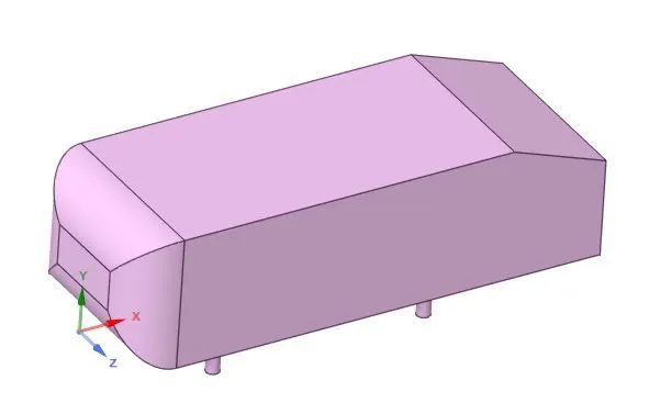
Length - 1.044m
Height - 0.288m
Width - 0.389m
It also has 0.5 m cylindrical legs at the bottom.
Significance of Ahmed Body :
The main goal of automotive industry is to reduce drag and prevent unwanted lift of vehicle and avoid instabilities that can occur at high speed. Hence to achieve above said goals the vehicle design and aerodynamics are the most important parameters. The drag on vehicle is experienced due to pressure difference between the frontal and rear end of car. The flow separation behind the ahmed body is mainly due to drag forces.
Geometry :
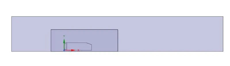
- Enclosure
As the body is perfectly symmetric, we can run the simulation by considering the only half portion of the body. So, we can get results faster as the number of cells will get reduced. The symmetric model is prepared from the given model using "split body" tool in spaceclaim.
- Ahmed Body, slant angle = 20 degree
Solver Settings :
- Reference Area :
projected area in the direction of x is set up in fluent.

Length - 1.044m
Velocity - 25m/s
Case (1)
For Default Mesh,
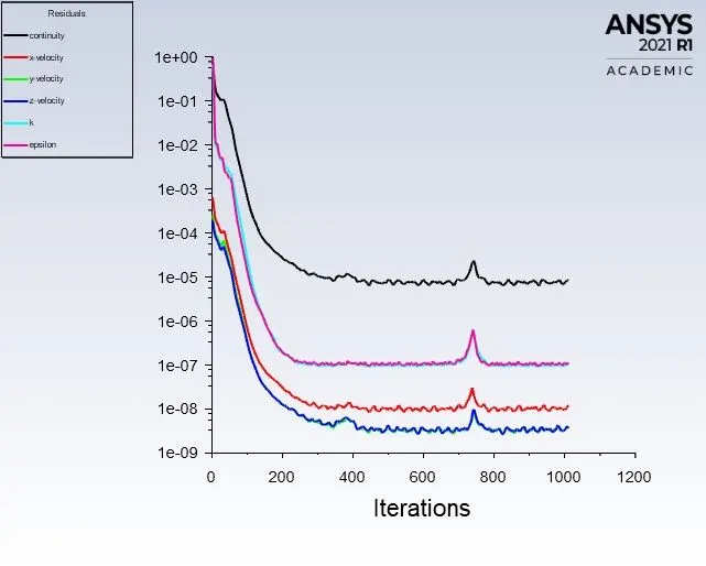
Residuals :
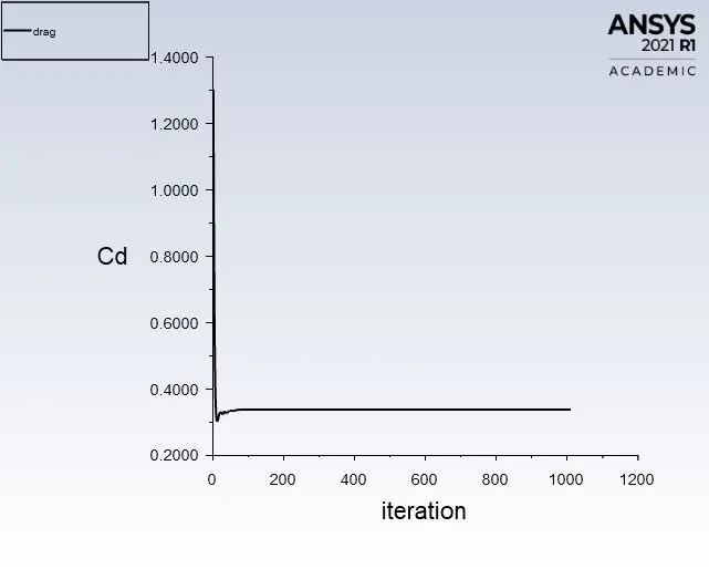
Drag Co-efficient Plot :
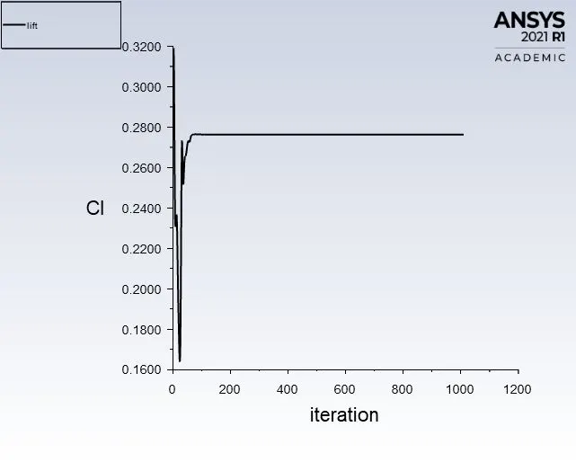
Lift Co-efficient Plot :
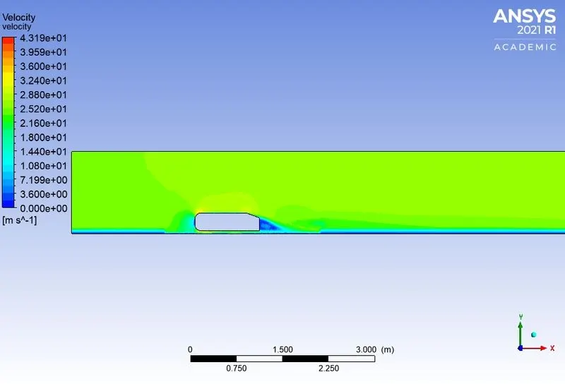
Velocity Contours on mid-plane :
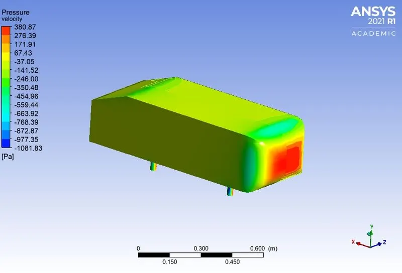
Pressure contour on Car-wall :
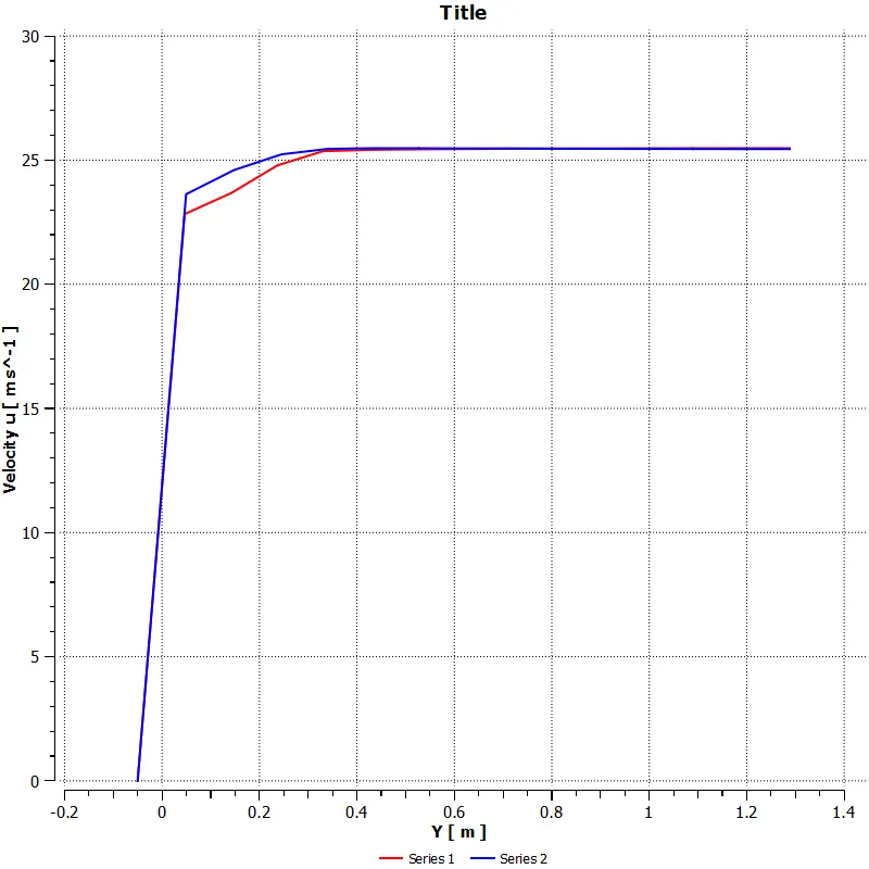
Velocity Variation along Vertical lines at 2.5 and 3.5m :
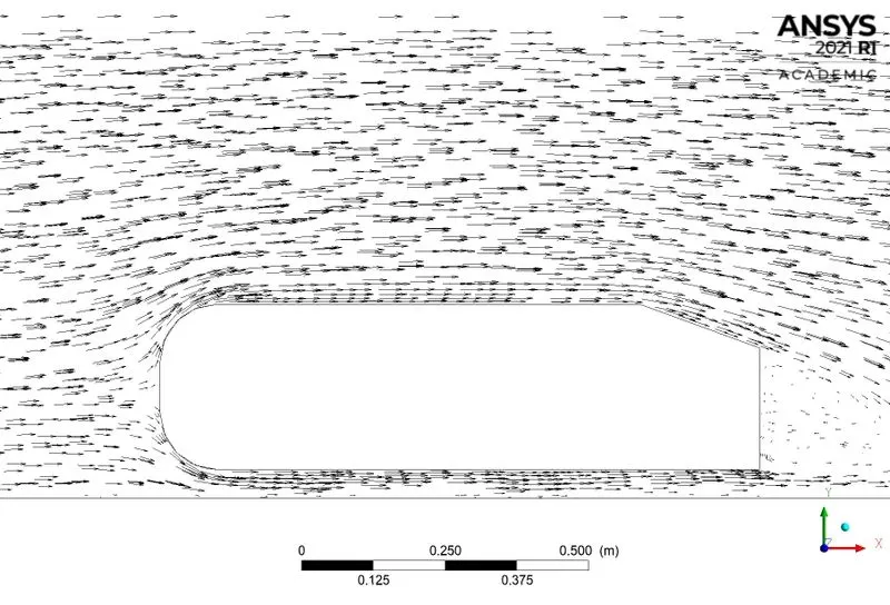
Vector Plot :
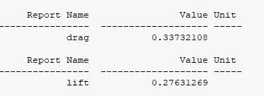
Drag and Lift Co-efficient Value on Car-wall :
Case (2)
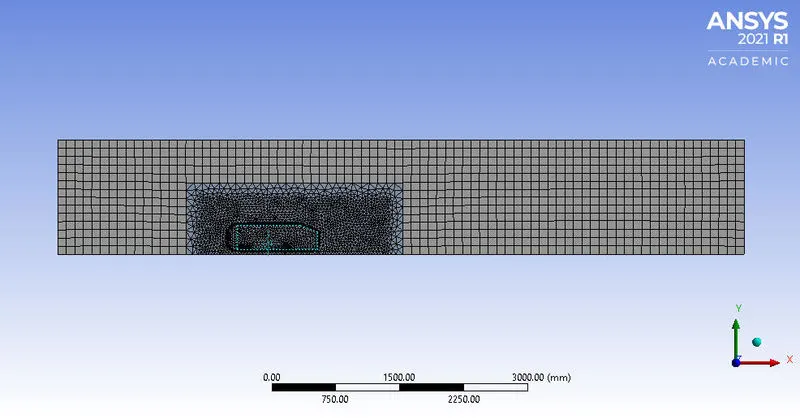
For refined mesh with
Element size at outer enclosure : 100 mm
Element size at inner enclosure : 32 mm
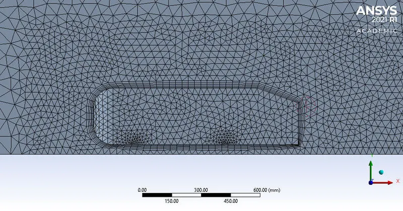
Inflation at car-wall with total thickness of 37.2 mm
Number of layers : 5
Growth rate : 1.2
Number of Elements : 226961
K epsilon, standard
Mesh :
Inflation Layer :
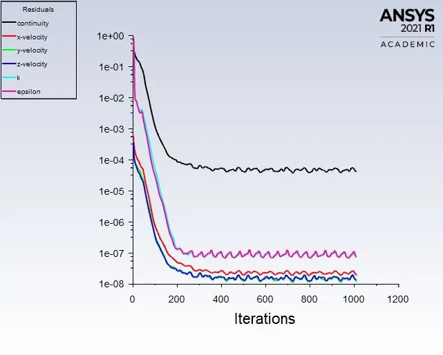
Residuals :
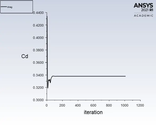
Drag Co-efficient Plot :
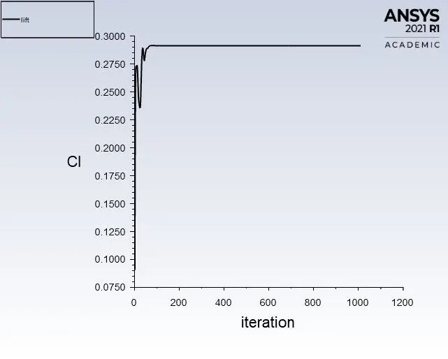
Lift Co-efficient Plot :
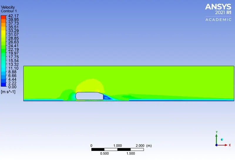
Velocity Contours on mid-plane :
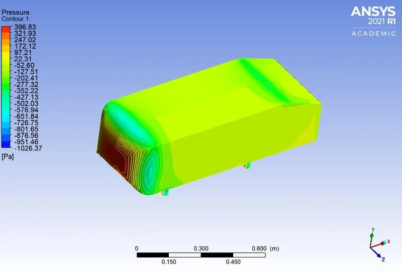
Pressure contour on Car-wall :
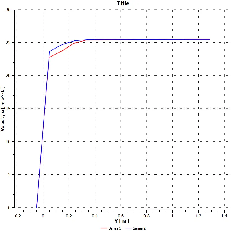
Velocity Variation along Vertical lines at 2.5 and 3.5m :
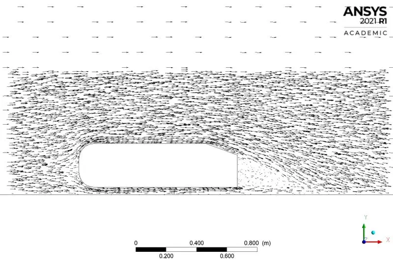
Vector Plot :
Drag and Lift Co-efficient Value on Car-wall :
Case (3)
For more refined mesh with
Element size at outer enclosure : 100 mm
Element size at inner enclosure : 48 mm
Inflation at car-wall with total thickness of 2.61 mm
Number of layers : 50
Growth rate : 1.2
Number of Elements : 271836
K-omega, standard
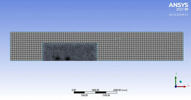
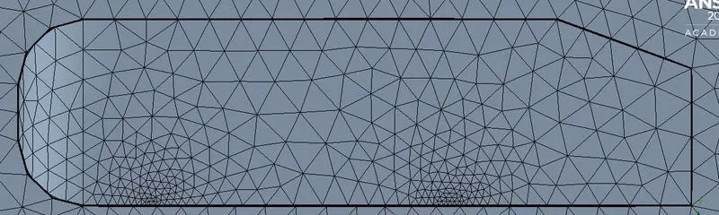
Mesh :
Inflation Layer :
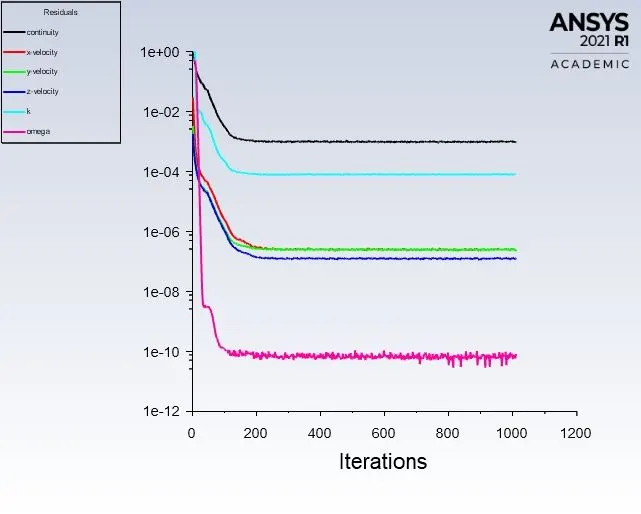
Residuals :
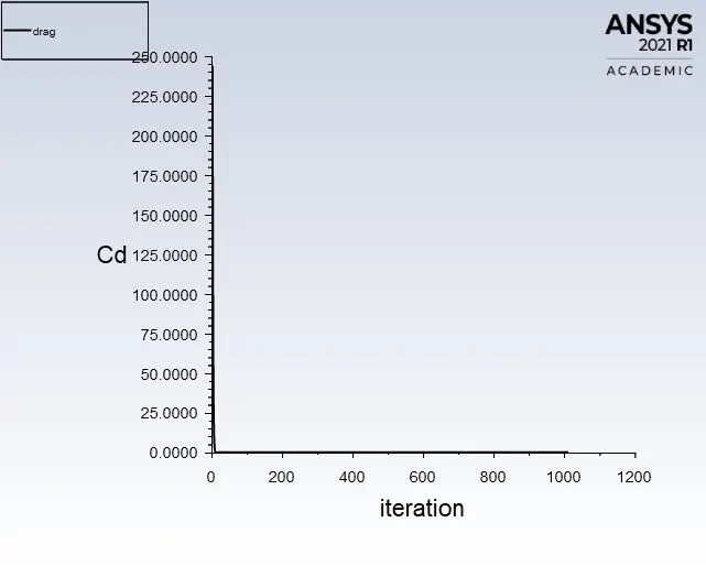
Drag Co-efficient Plot :
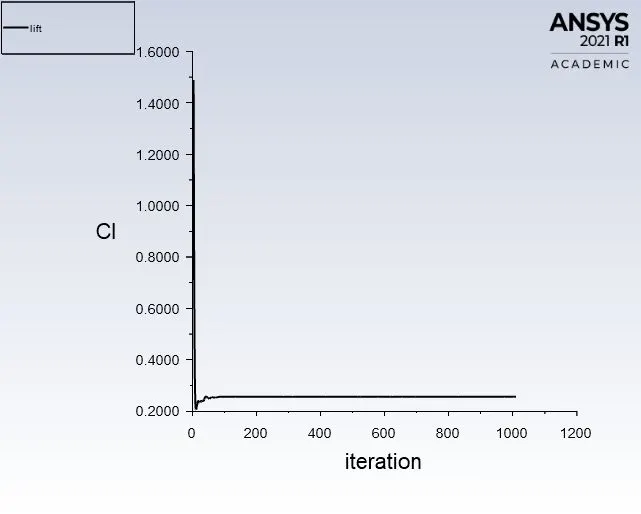
Lift Co-efficient Plot :
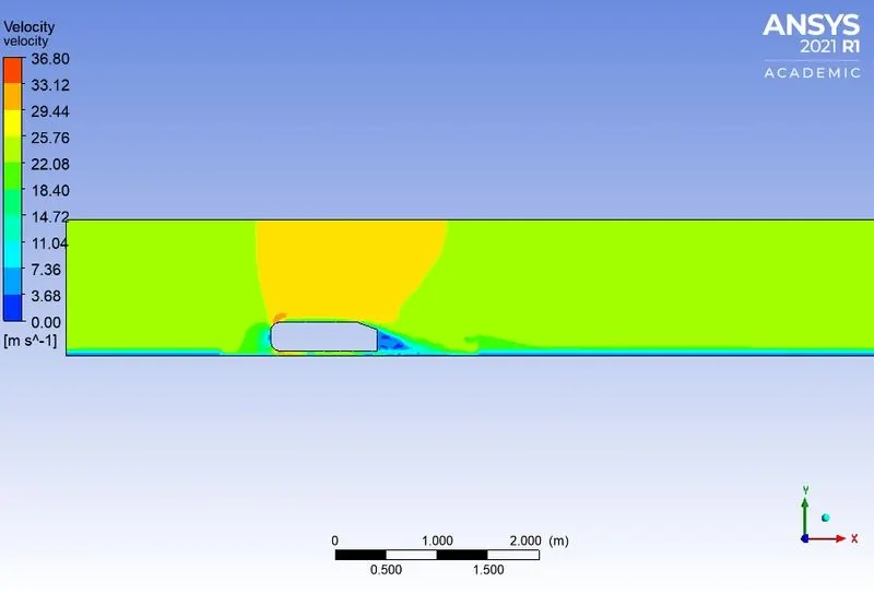
Velocity Contours on mid-plane :
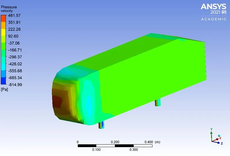
Pressure contour on Car-wall :
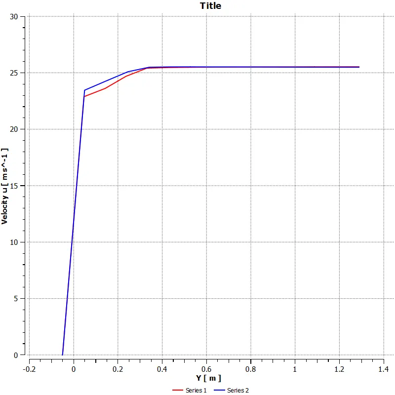
Velocity Variation along Vertical lines at 2.5 and 3.5m :
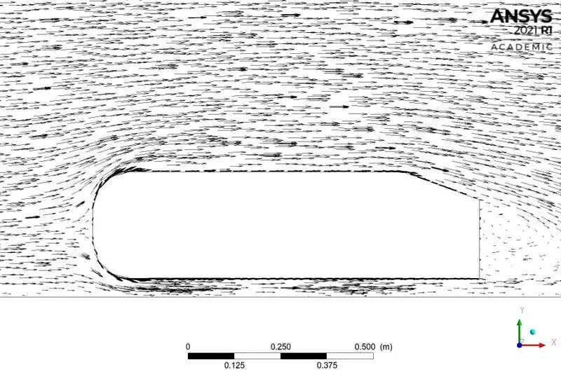
Vector Plot :
Drag and Lift Co-efficient Value on Car-wall :
Mesh Independency Test :
| Cases | Mesh Elements | Outer Enclosure (mm) | Inner Enclosure(mm) | Drag co-efficient | Lift co-efficient |
| 1 | Default mesh | - | - | 0.3373 | 0.2763 |
| 2 | 226961 | 100 | 32 | 0.3380 | 0.2912 |
| 3 | 271836 | 100 | 48 | 0.3641 | 0.2562 |
Why is the negative pressure in the wake region?
As we know that when there is relative motion between fluid and solid round body, boundary layer will exist near the wall of body. The boundary layer may be laminar or turbulent. The separation of flow occurs when flow is slowing down, with increasing pressure, after passing thickest part of streamlined body. The flow reversal takes place when there is negative pressure gradient also called as adverse pressure gradient. when the flow is detached from the surface, it takes in the form of eddies and vortices. Separated flows result in reduced lift and increased pressure drag, as there exist the pressure differential between the front and rear end of object.
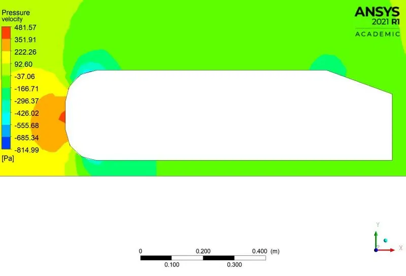
The separation takes place due to excessive momentum loss near the wall in the boundary layer trying to move downstream against increasing pressure. i.e., dp/dx > 0, which is called adverse pressure gradient. At separation point the velocity gradient is zero and thus wall shear stress is also zero.
Conclusion :
- The velocity and pressure contours for each cases are listed above as well as the drag co-efficient values are also found for each cases.
- By refining the mesh, the value of drag co-efficient looks better (cd - 0.33)
- Understanding the mesh sizing and Y+ values, because it greatly affects the accuracy of the model.
- Drag and lift co-efficient values should be constantly maintained so as to maintain the stability of the vehicle.
- By splitting the model, which help us to reduce the number of elements and increase the calculation speed.