Week 4 - CHT Analysis on Exhaust port
AIM:
To perform a CHT analysis on an exhaust port using ansys fluent and study various parameters that effect the rate of heat transfer in the exhaust port.
CONJUGATE HEAT TRANSFER:
The term conjugate heat transfer can be used to describe the processes which invlove a temperature variation within the solids and fluids itself due to the thermal interaction between the solid and the fluid.During CHT the heat transfer can take place from solid media to the fluid media and viceversa.A common example to the conjugate heat transfer can be the cooling or heating of a solid object by the flow of air over them.
CHT analysis is benficial in engineering applications because it shows the heat excahnging capabilities between the two surfaces in the engineering device and various optimization can be done to improve the thermal characteristics of the devices.Thus,this can be used to improve the heat transfer rate wherever required.It alos helps us to iddentify the key parameters that enhance the fluid flow and heat transfer within the system.
Conjugate heat transfer corresponds with the combination of heat transfer in solid and fluid.In solids the conduction often dominates,wherereas in fluids,convection dominates.Efficiently combining heat transfer in fluids and solids is the key to designing effective coolers,heaters or heat exchangers.The forced convection is the most common way to achieve high heat transfer rate.In someother applications,the performance are further improved by combining convction with phase change.Heat transfer in solids and fluids are combined in majority of applications.This is because fluids flow around solids or between solidwalls,and also the solids are mostly immersed in a fluid.Some of the applications where the CHT can be employed are given below.
- CHT can be performed to improve the cooling performance of water jackets and increase the engine life.
- Advancements n cooling of applications such as gas turbine components can be achieved after understanding the compplex heat transfer mechanisnm and interactions between the media
- CHT analysis can be done for bikes,passenger vehicles etc.
1.GEOMETRY:
2.MESHING:
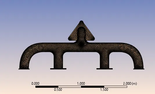
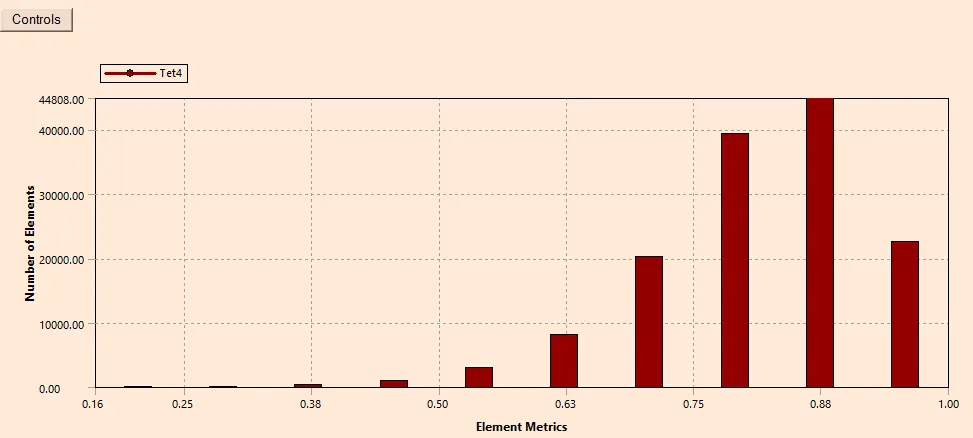
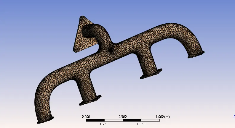
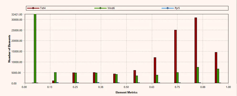
The meshing for the simulation has been done in two different cases ie, one with a base line mesh and the other with a more refined mesh.The mesh profile of the exhaust port for the tow cases has been shown below.
CASE-A : BASELINE MESH
- Element Size: 150 mm
- Type of mesh element : Tetrahedral
- Number of Elements :138876
- Number of nodes : 27692
CASE-B: REFINED MESH
- Element Size: 150 mm
- Type of mesh element: Tetrahedral
- Number of Elements: 180432
3.SETUP:
- The case has been simulated with two different cases as mentioned earlier with a base line mesh and the other with a refined mesh and within each case the turbulence model k-epsilon and k-omega SST has been employed for each cases.
ie, CASE-A: k-epsilon turbulence model
CASE-B : k-omega SST
rest of all the setup for both the cases remains the same,and are discussed below:
- Pressure-based solver
- Steady-state simulation
Model : k-epsilon realizable and k-omega SST turbulence model for the aforth mentioned cases.
Material : Fluid - Air
Solid - Aluminium
Boundary Conditions: - inlets : velocity inlet ( 5m/s)
Temperature 700 K
- Outlet : Pressure-outlet ( zero gauge pressure )
- Outer-wall : Convection Boundary condtion with convective heat transfer coefficient 25Wm2K">25Wm2K25��2�
Residual with convergence condition unchecked
- SIMPLE Solver.
4.SOLUTION & RESULTS:
CASE 1:
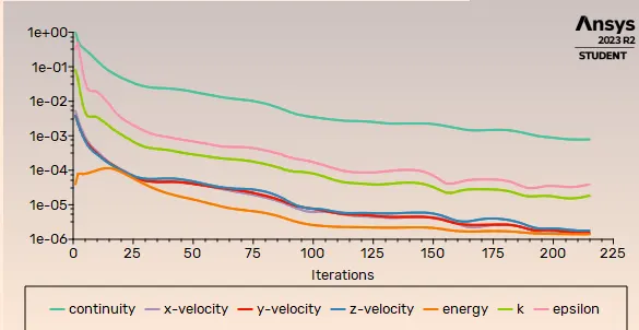
1. Residual Plot:
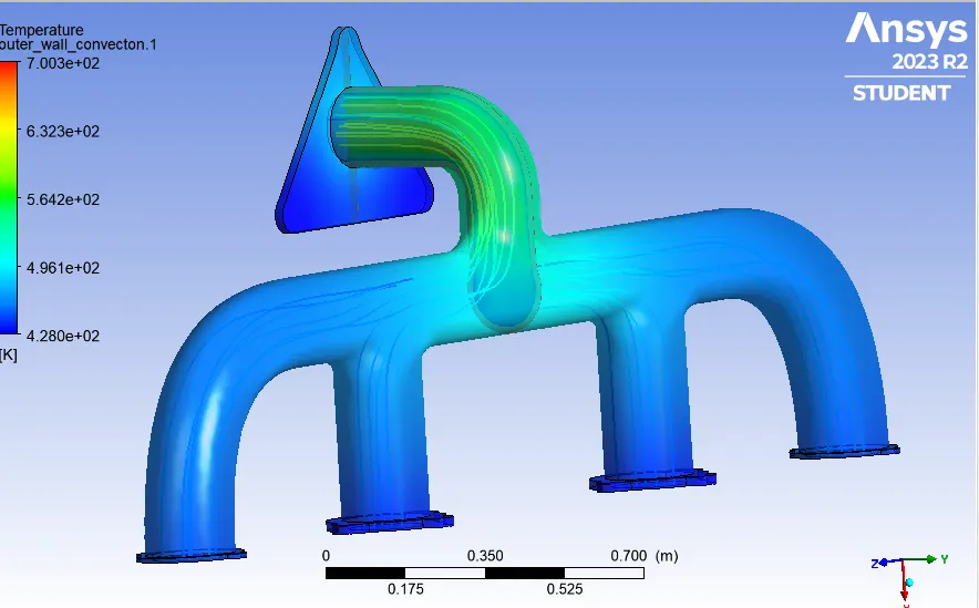
2. Temperature Contour:
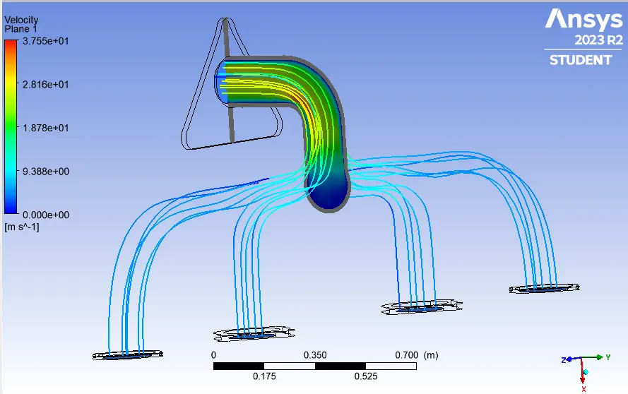
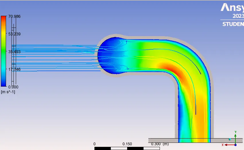
3. Streamline Plot for Velocity:
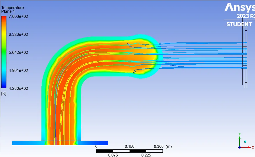
4. Temperature contour across a plane at the outlet bend:
5. Velocity contour across the plane at the outlet bend:
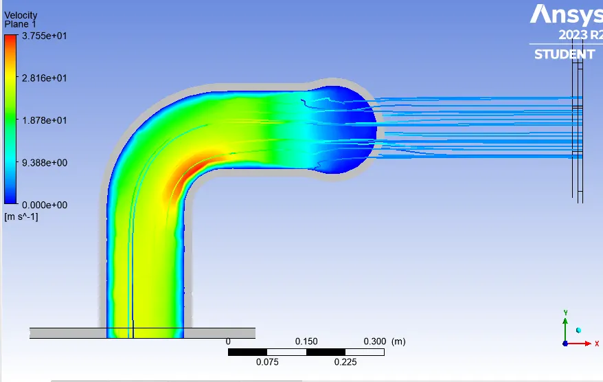
CASE 2:
1. Residual Plot:
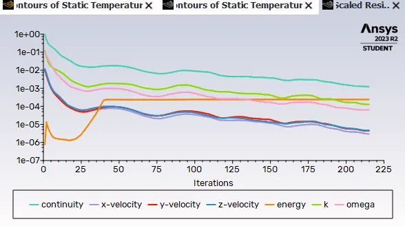
2. Temperature Contour:
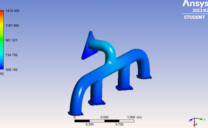
3. Streamline Plot for Velocity:
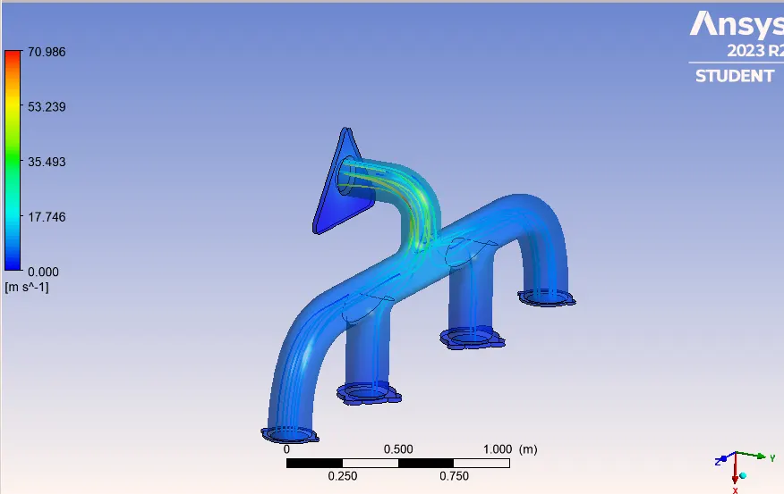
4. Velocity contour across the plane at the outlet bend:
From the above table, it can be summarised that as the mesh is becoming finer and due to the interpolation of more number of elements,the simualtion becomes more practical and the it can be noted that the as the velocity is increased which further rises the Reynolds number and as a result the heat transfer coefficient is increased which leads to more heat transfer rate along the walls of the exhaust manifold.This increase in heat transfer rate can be further verified by checking at the outlet temperature of vehicle exhaust in all the four simulations.We are able to observe that as the h.t.c increased the temperature at the outlet is also reduced.