Week 4 - CHT Analysis on Exhaust port
OBJECTIVE :
To Perform a CHT(Conjugate heat transfer) Analysis on a Exhaust Port given and to Estimate the Heat Transfer Coefficient on the outer wall.
CHT ANALYSIS
CHT Analysis are used to study the heat energy transfer corresponding two mediums , In this case (Solid - Air) medium is established on the Exhaust Port. These Analysis are so significant in terms of estimating Heat flux, Temperature difference, Thermal inputs in the corresponding mediums, Simulation of Heat Transfer Coefficient,Heat Flow study and the physics goes on.
BASELINE MESH SETUP.
GEOMETRY
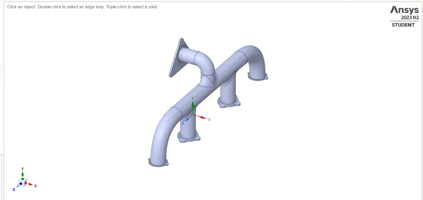
SOLID VOLUME
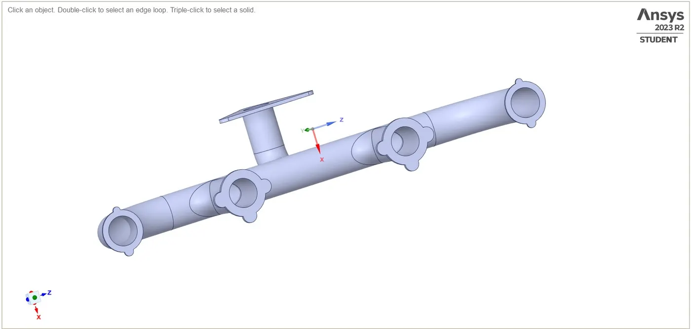
LIQUID VOLUME
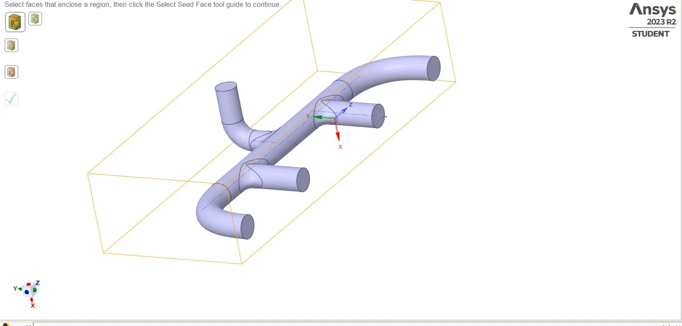
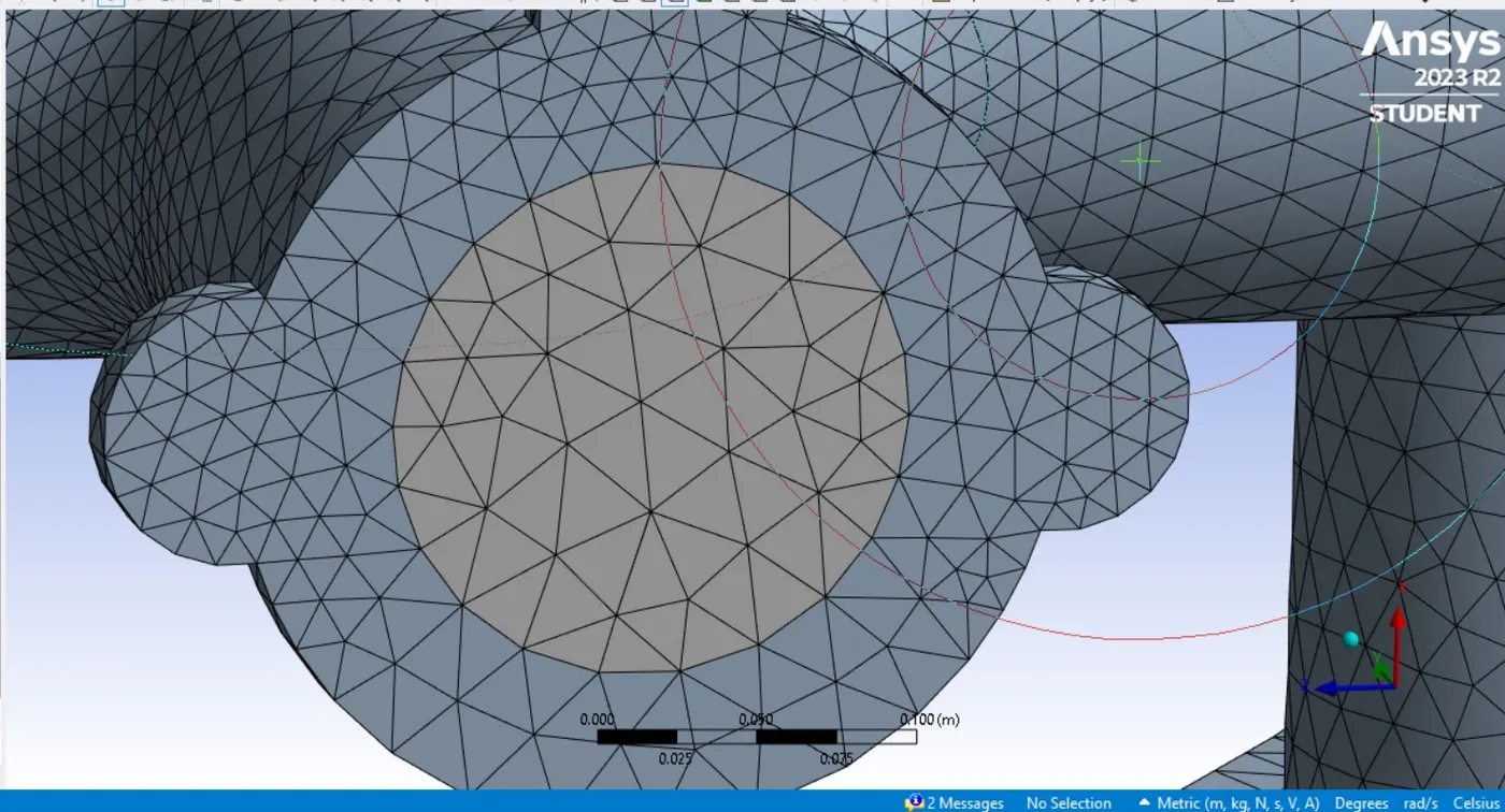
This separation of volume avoids the mesh interaction between the mediums as the mesh formed is a non conformal mesh . These types of meshes are avoided as the mesh interface fails to tranfer information from one medium to other medium.
Non conformal mesh
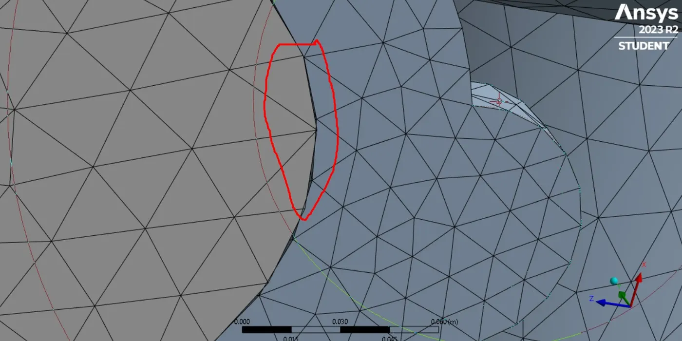
Conformal mesh
SETUP
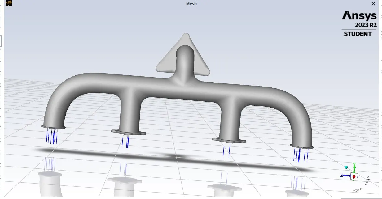
Boundary conditions and named selection are made for the setup purpose as the geometry is differentiated into Inlet,Outlet and Outer wall Convection.
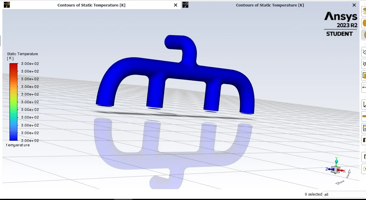
Temperature disturbution at initial stage
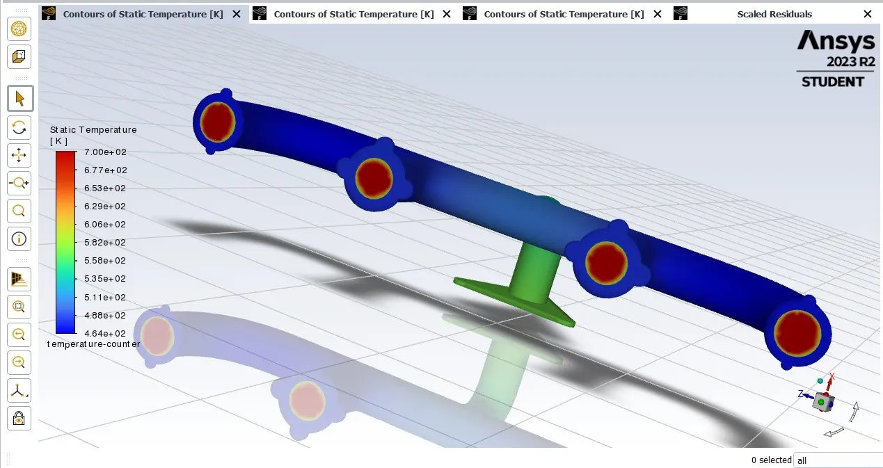
RESULT
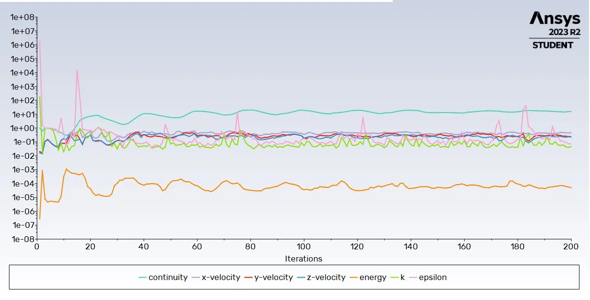
Residual
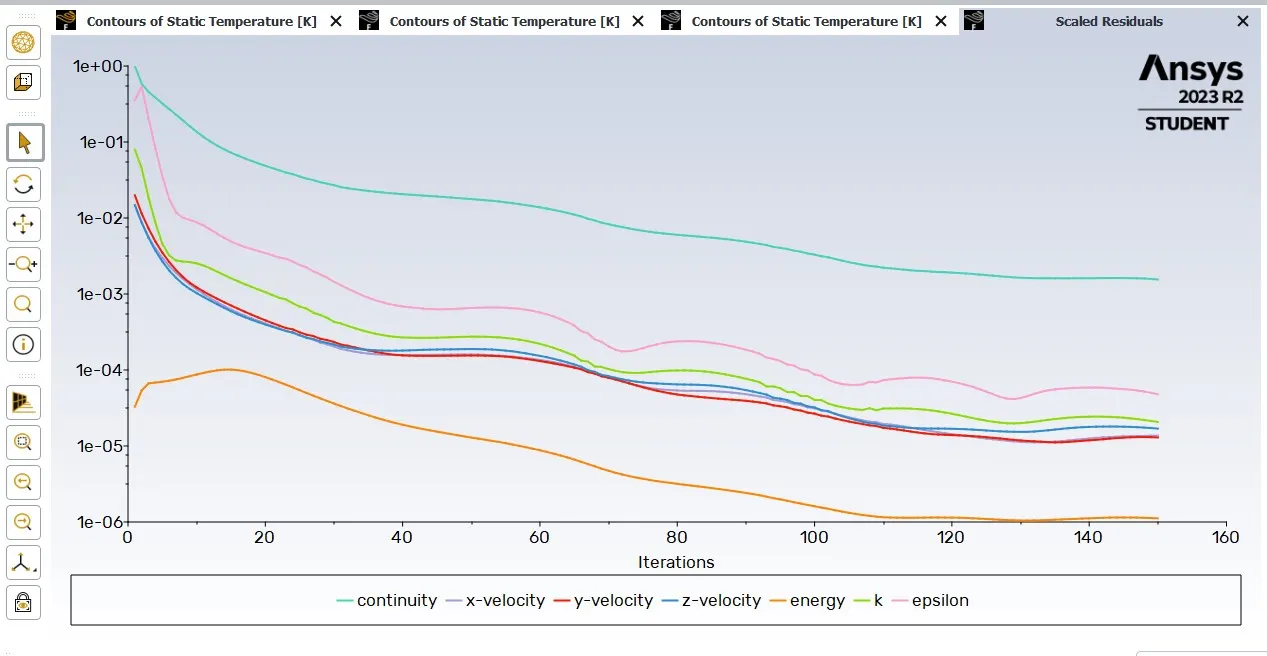
REFINED CASE WITH INFLATATION LAYERS
Y + Significance
Generally for giving the Y+ input for the mesh , Where it takes the significance should be known. The Boundary layer of the material is keenly differntiated into three layers namely
- Viscous sub layer (Laminar flow)
- Buffer layer (mix of laminar and turbulent)
- Logarithmic layer (turbulence)
Viscous sub Layer
Viscous sub layer is dominated by laminar flow as this layer stays very close to the end wall where the slip velocity is zero . This is the first layer differntiation from the boundar layer from the end wall.
Buffer layer
Buffer layer is the second layer from the end wall and is the middle layer between viscous sub layer and logarithmic layer. Here the flow condition is a mix of laminar and turbulence.
Logarithmic layer
It is the most outer boundary layer where turbulence flow dominates as it stays a bit far from the slip wall conditions.
Y + values are so significant whenever the boundary layer wall functions comes into consideration, Y+ plus values are determined with a calculation and implented on the first layer thickness of the Inflation layer and the rest of thellayers are segmented with a multiplication factor
Y+ values are important as the mesh element size for the boundary layer decides for capturing the physical data while in simulation. Y+ values are decided based on the calculation inputting Velocity, characteristic length, dynamic viscosity, and density.
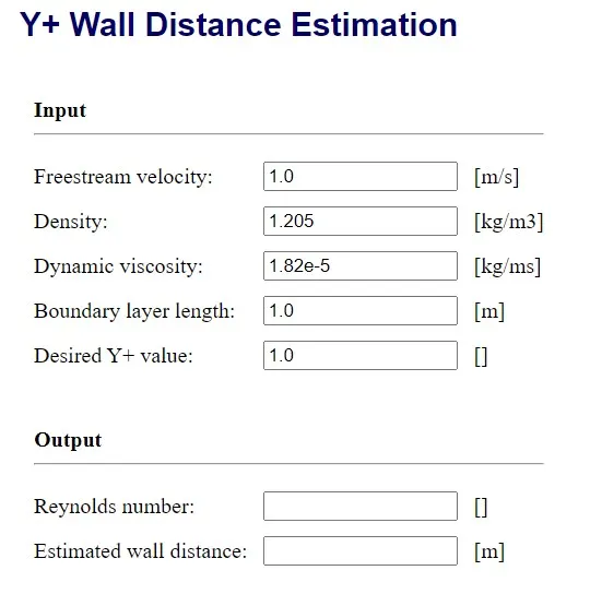
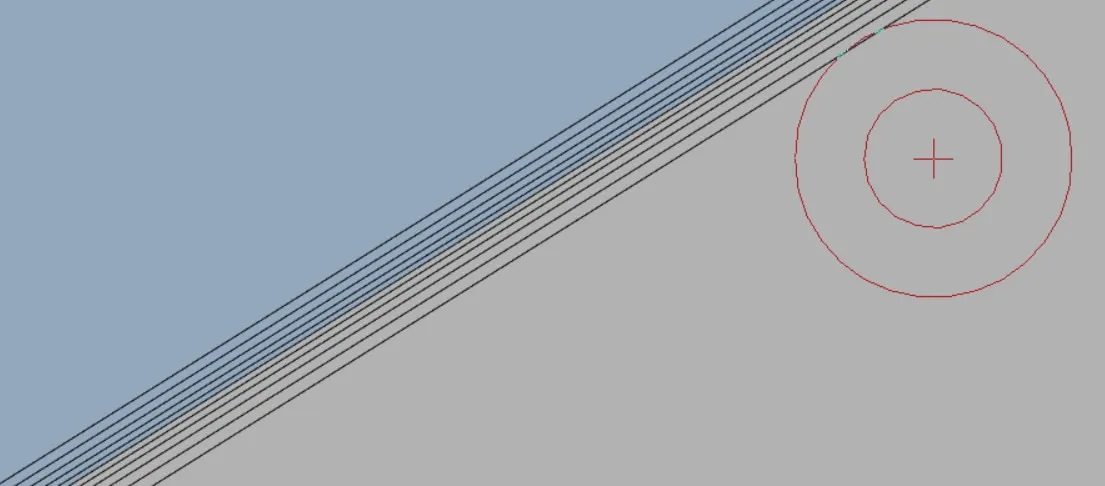
Simulation is done on the same geometry with inflation layer added (Y+ thickness included) for this case
Geometry with Inflation Layer
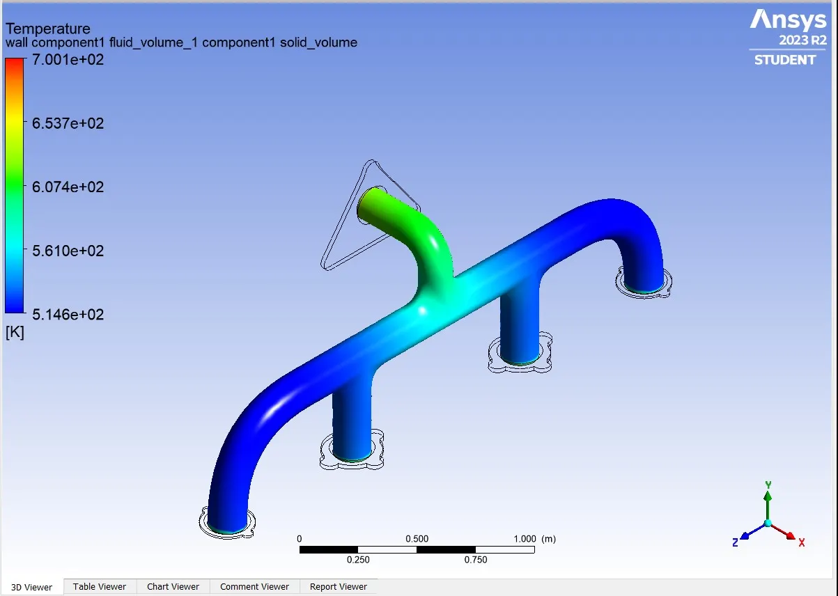
Temperature Distribution on the Exhaust port after simulation
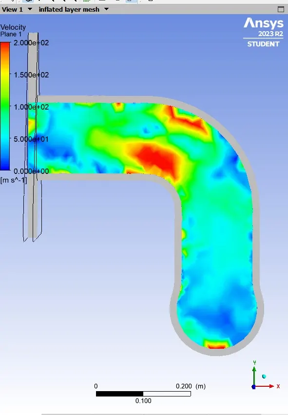
Velocity distribution on the plane intersecting the Exhaust port
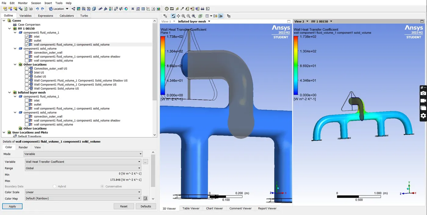
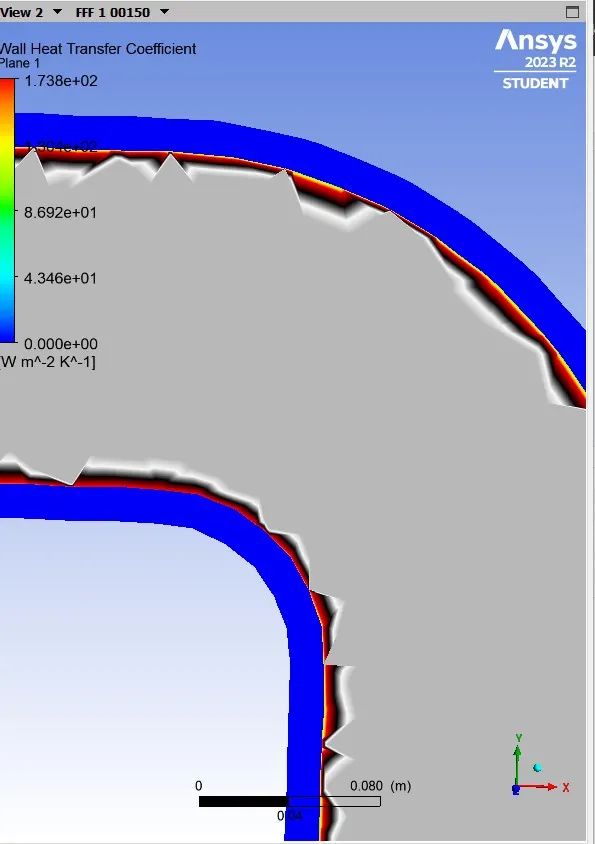
Heat transfer coefficient on the plane
CONCLUSION
- Heat transfer coefficient value is high on the bending curve of the plane as the velocity of the outflow air is high on the region which results for larger Reynolds number and the temperature distribution between the medium on the curve plane is comparitively large.
- More velocity - More Reynolds number - High Heat tranfer - More temperature on the area.
HTC predicitions are concluded on repeated simulation basis with the setup approaching towards a finer mesh , So the value simulated from the most refined case would give a more appropraite assumption on the CFD Simulation.