Week 4 - CHT Analysis on Exhaust port
Aim:
(i)To understand the Conjugate Heat Transfer and its applications
(ii)To determine the Heat Transfer Coefficient (HTC) on the internal wall surface by maintaining the y+ value according to the turbulence model.
(iii)To understand behaviour of the fluid with the help of the velocity and temperature contours at significant locations
(iv)To identify the factor, accuracy of HTC depends on.
(v) To validate the results.
Introduction:
Fluids flow through pipes is most commany used in heating,cooling and fluid distribution applications.A fluid is forced to flow by the fan or pump(external source araised due to the friction,pressure drop) through the pipes or ducts.Small diameter compared to the length of the pipe are called tubes.Pipes are refered to the circular cross-section and Ducts are refered as non-circular cross-Section.Due to the strength of the pipes will gets a lot of importance in transportation applications.Reynolds number depends on the surface rougness,flow velocity, geometry,surface temperature and type of the fluid.Reynolds number will allows to make a decision between theortictical solutions or experimental and empirical solutions based on regimes such as laminar,transition and turbulent.Fluid velocity in a pipe changes from Zero at wall (no-slip) to maximum at center it creates a environment to work with average velocity and it would constant even for the compressible flow.No-slip condition gives raise to boundary layer concept it was introduced by ludwig prandtl on the problem of flow separation.velocity boundary layer is different for both laminar and turbulent flow.Laminar boundary layer would occur in the laminar flow,condition is that viscous force dominates the inertial forces where Reynolds number <2300 and remaining part is irrotational (core) region it appears large when the hydrodynamically flow is developing(hydronamic entry length is length of flow is developing),if flow is hydodynamically fully developed (velocity wont change in flow direction) boundary layer occupies the entire pipe.Turbulent boundary layer would occur in the turbulent flow,condition is that inertial force dominates the viscous forces on the turbulent core layer,vice versa for viscous sublayer,buffer, overlap layer, where reynolds number > 4000.Dynamic viscosity refers to the resistance for the fluid motion,moving of particles will generate sensible thermal energy due to friction (viscosity) between the particles and that generation of thermal energy is so small.Thermal boundary layer will present if the the fluid temperture and surface of surrounding medium has the different temperature.Due to this ,fluid properties used for analysing should be bulk mean fluid temperature.Nusselt number is insensitive to the thermal boundary condition in the turbulent flow and vice cersa for laminar flow.Developing turbulent flow can be approximated as developed turbulent flow in pipes , for better accuracy literature for developing turbulent flow is available.Thermal boundary layer and velocity boundary layer develops simultaneously.If both the boundary layer is developed then we can say that the flow is dveloped.Prandtl Number is useful to know the comparision between the velocity boundary layers and thermal boundary layer.For liquid metals prandtl number is less than 1 indicates that that thermal energy diffuses more quicky where oils has prandtl number greater than 1 indicates the momentum diffuses more quickly.velocity and temperature profiles are steep for the turbulent boundary layer which results in increase of the wall shear stress and wall heat flux.Consequence of friction is pressure drop and temperature change is due to heat transfer.Friction and heattransfer in the pipe reaches maximum when it is fully turbulent.In turbulent flow surface roughness becomes the strong function of the friction factor we can get from moody chart or colebrook equation.Assumption (based on the colebrook-white literature) of the pipe whether it is smooth or rough based on the surface ,if it is fully submerged inside the viscous sublayer then it is assumed as smooth pipes and if surface not fully submerged in the viscous sub layer of turbulent flow then it is called as rough pipes.Surface roughness miniumum for fiberglass and maximum for concretes and machined surfaces needs an calculate the twice the RMS value of absolute roughness. friction factor is independent of reynolds number on the fully developed turbulent flow leads to fully rough developed flow.various fittings such as valves, bends, elbows, tees, inlets, exits, expansions, and contractions are leads to head loss,it directly increases the pressure drop.
The Dean number, a dimensionless number giving the ratio of the viscous force acting on a fluid in a curved pipe to the centrifugal force, has frequently been employed in the study of flow in curved pipes and channels.The flow is completely unidirectional for low Dean numbers (De < 40~60). As the Dean number increases between 40~60 to 64~75, some wavy perturbations can be observed in the cross-section, which evidences some secondary flow. At higher Dean numbers than that (De > 64~75) the pair of Dean vortices becomes stable, indicating a primary dynamic instability. A secondary instability appears for De > 75~200, where the vortices present undulations, twisting, and eventually merging and pair splitting. Fully turbulent flow forms for De > 400. Transition from laminar to turbulent flow has also been examined in a number of studies, even though no universal solution exists since the parameter is highly dependent on the curvature ratio. Somewhat unexpectedly, laminar flow can be maintained for larger Reynolds numbers (even by a factor of two for the highest curvature ratios studied) than for straight pipes, even though curvature is known to cause instability.It doesnot employed in bendloss coefficient.If pipe has a bend, sufficient length is needed after the bend for flow turning from developing to developed.
Pipes many connected serially then the flow rate should be constant,if pipes are connected parallel then the pressure drop on the individual branch should be same.Internal flow consists of various flow phenomena (i) absolute pressure decreases below the vapour pressure then cavitation takes place (ii)Water hammer is due to sudden blockage leads to the pressure rise on the walls may breaks the srtucture (iii)A water hammer - type event called Column separation may occur in a pipeline filled with liquid when a vapor cavity forms and suddenly collapses. This results in a large and nearly instantaneous rise in pressure due to the collision of two liquid columns, or the collision of one liquid column with a closed end (iv)Another related phenomenon, known as steam hammer , might occur in vapor distribution systems. Some vapor may condense into liquid in a section of piping and form a slug. Subsequently, the vapor may hurl the slug at high velocity into hydraulic equipment or into pipe fittings and cause major problems.(v)Head loss due to friction ,converted into the thermal energy will rise the temperature of the fluid.(vi) full flow (or flow to run full) for a heavy fluid discharging into a large space or chamber filled with a light fluid. The flow rate is just suffificient to fill the opening with heavy fluid; any decrease in flowrate would allow the formation of a pocket of light fluid at the top of the exit plane of the opening.
Heat is a form of energy that can be transferred from one system to another system as a result of temperature difference with the help of heat transfer mechanisms.Heat transfer mechanisms are conduction,convection and radiation.Conduction is the transfer of energy from the more energetic particles of a substance to the adjacent less energetic ones as a result of interaction between the particles.conduction can take place in solids,liquids or gases.In gases and liquids,conduction is due to the collisions and diffusion of molecules during their random motion.In solids,it is due to the combination of vibrations of molecules in lattice and energy transport by free electrons.Convection is the transfer of energy between a solid surface and the adjacent liquid or gas that is in motion and it involves the combined effects of conduction and fluid motion.The faster the fluid motion, the greater the convection heat transfer.In absence of any bulk fluid motion,heat transfer between a solid surface and the adjacent fluid is by pure conduction.Both phenomena plays a vital role in the boundary layer development.Radiation is the energy emitted by the matter in the form of electro magnetic waves as a result of the changes in the electronic configurations of atoms or molecules.Unlike conduction and convection, the transfer of heat by radiation does not require the presence of an intervening medium.Among all heat transfer mechanisms radiation is the fastest energy transfer mechanism.
An exhaust system is used to guide reaction exhaust gases away from a controlled combustion inside the engine(or)stove to the atmosphere.various components helps to build the exhaust system.Those components are exhaust manifold, catalytic converter, muffler.
(i)Exhaust Manifold
Exhaust manifold is used to connect the multiple cylinders to one single outlet or two outlet pipes.Mostly, automobile manufacturers use castiron material due to heat managment properties and superior longevity.stainless steel and aluminium exhaust manifold used in passengar cars .Exhaust manifold contains a inefficiences due to 2 or more combustion cylinders.The reason behind it ,exhaust leaves them at different times ,pressure waves from gas emerging from one cylinder might not be vacated through the exhaust system when another comes.this creates the back pressure which affects the engine performance by not scavenging the whole exhaust gas from cylinder.Geometry of exhaust manifold circular tubing with a bends and narrow angles for connecting (2 or more inlets to outlet) for travelling of pressure waves to outlet.Lengths should be calculated to enhance the exhaust flow for range of RPMs
(ii)Catalytic convertor
Main Purpose of Caralytic converter is to convert harmful emissions of hydrocarbons,carbon monoxide and nitrogen oxides into the water and carbon dioxide to avoid polluting an atmosphere.back pressure and clogging will damages the whole component.Emission standards would be desribed by government regulations.There are three different types of catalyst (a)oxidation catalyst (b)dual-bed catalyst (c)threeway
Oxidation catalyst decreases harmful pollutants like CO (carbon monoxide) & HC (fuel hydrocarbon) within the exhaust. At the same time, it frequently utilizes an inferior air injection. But, this type of catalyst simply decreases a part of the pollutants.
dual-bed catalyst mainly works within two stages where the first stage assists in decreasing the emission quantity from NiO2. The second phase responds through the hydrocarbons which are formed through unburned carbon mono oxide & fuel. In two stages, the manufacturers will provide the secondary air injection.
The car engine will exhaust different gases which include hazardous substances that cause harm to the atmosphere like NiO2, CO, CO2, etc. Threeway converts mainly change them into less harmful CO2, nitrogen & water. So, most of the designers use this type of converter within their cars which requires them to meet harsh emission values.
(iii)Muffler
It is typically used to reduce the noiselevel from the tailpipe by bouncing sound waves off of the back, front, and sides of the muffler.ceramic coating applies via thermal spraying. The three primary types of mufflers are Chambered, Turbo, and Straight-Through.
Chambered mufflers are the mufflers that contain the chamber which forces the soundwaves to collide (or) cancel each other.increase in chamber will reduce the noise.
Turbo mufflers guide exhaust gases through s shape perforated pipes.it uses sound deadening material.quality of sound describe as rapsy.
straight-through mufflers are perfect for people looking to reduce backpressure but who don’t want loud cabin noise. This way you can get performance and enjoy your music on the road.Many straight-throughs use absorptive material, like fiberglass, to deaden sound. These materials can suffer blowout over time. Some well-designed straight-throughs avoid this with options like stainless steel mesh, or waterproof lining to keep the fiberglass dry.
This study focus on one of the component of exhaust system i.e..,exhaust manifold.Exhaust manifold opted for study would be suitable for inline 4 Engine,v-8 Engine,H-8 Engine,Boxer 8 Engine etc..,.Our study primarily focuses on the heat transfer through fluid and solid.To study both heat transfer under the one type of analysis that is called Conjugate Heat transfer analysis.
Conjugate Heat Transfer:
In the traditional area of convective heat transfer between a solid wall and a fluid flow,the wall conduction resistance is usually neglected, i.e. the wall is assumed to be very thin. In this case it is usual to prescribe either the wall temperature or the wall heat flux, and a considerable amount of research work has been done in order to understand the heat transfer characteristics over a wide range of flow configurations and fluid properties. However, in many real engineering systems the wall conduction resistance cannot be neglected since conduction in the wall is able to significantly affect the fluid flow and the heat transfer characteristics of the fluid in the vicinity of the wall. In order to take account of physical reality, there has been a tendency to move away from considering idealized mathematical problems in which the bounding wall is considered to be infinitesimally thin. Thus, the conduction in the solid wall and the convection in the fluid should be determined simultaneously. This type of convective heat transfer is referred to as a conjugate heat transfer process and it arises due to the finite thickness of the wall.
Applications-Conjugate heat transfer effects are of considerable importance in many practical problems, e.g. in ablation or perspiration cooling problems as well as in heterogeneous chemical reaction situations, where information on the interfacial temperature and concentration distributions is essential because the transfer characteristics are mainly determined by the temperature and concentration differences between the bulk flow and the interface. Further, these effects occur also in the design of thermal insulators and in material processing and geothermal systems. Ventilation and cooling applications.In particular, it has been ascertained that free convection can induce the thermal stresses which lead to critical structural damage in the piping systems of nuclear reactors, see Hong (1977), food processing, from complex procedures in medicine to atmosphere/ocean thermal interaction in meteorology, and from relatively simple units to multistage, nonlinear processes
It is also worth mentioning that recent demands in heat transfer engineering has led to new types of heat transfer equipment which has a superior performance, especially in compact and light-weight equipment. Increasing the need for small-size units, research has focused on the effects of the interaction between the development of the boundary-layer near to the wall and on the axial wall conduction, which usually degenerates the performance of the heat exchanger.
It appears that the topic of conjugate heat transfer was originated by Perelman (1961), who was the first to study the boundary-layer equations for the fluid flow over a flat plate of finite thickness with two-dimensional thermal conduction taking place in the plate. He derived theoretical expressions for the interfacial temperature and the local Nusselt number. The investigation was then extended by Luikov et al. (1971) and since then various types of conjugate heat transfer problems have been studied. Conjugate problems can be roughly classified into the following three groups from the viewpoint of fluid flow situations: (a) one or two forced convection flows; (b) one or two free and mixed convection flows; and (c) one forced convection flow and one free or mixed convection flow. In the earlier investigations, the first type of problem (a) was intensively studied because the fluid flow was not greatly influenced by the heat transfer in the incompressible fluid and the equations of motion and energy could be solved separately. However, problems of the types (b) and (c) have been more recently investigated because of the difficulties in solving the coupled equations of the fluid flow and the heat transfer simultaneously, but the present computer facilities has lead to detailed solutions of these types of problems.
From the class (b), one case which has received much attention in the past has been that of the two-dimensional free convective flow of a viscous incompressible fluid heated by a vertical conducting fiat plate of finite thickness. Important contributions to the cases (b) and (c) of flow type problems were made by Lock and Ko (1973), Anderson and Bejan (1980), Viskanta and Lankford (1981), Sakakibara et al. (1992), Cdrdova and Trevifio (1994), Trevifio et al. (1996), M@ndez and Trevifio (1996), Camargo et al. (1996), Chen and Chang (1996, 1997) and Shu and Pop (1999).It has been concluded from these studies that it is very difficult to obtain analytical solutions of conjugate heat transfer problems due to the matching conditions at the solid-fluid interface, but the use of numerical methods, such as finite-difference schemes, is the most It has been concluded from these studies that it is very difficult to obtain analytical solutions of conjugate heat transfer problems due to the matching conditions at the solid-fluid interface, but the use of numerical methods, such as finite-difference schemes, is the most promising procedure for performing this matching
Formula:
1.`Re=frac{rho*V*D}{mu}`
Re-Reynolds Number
`rho`-Density-1.225 `frac{Kg}{m^3}`
V-Velocity-5 `frac{m}{s}`
D-Hydraulic diameter-0.15 m
`mu`-Dynamic viscosity-0.000017894 `frac{Kg}{m s}`
After substituting the air property values in the above formula , we get `Re=51344.026`
As Reynolds number > 4000 will leads a tubulent flow in the pipe.
2.`triangley=frac{y^+*mu}{rho*u^ast}`
`u^ast=sqrt(frac{tau}{rho})`
where `u^ast-`frictional Velocity,`tau-`Wall shear stress,`rho-`Density
`mu-`Dynamic viscosity
Geometry:
Geometry would be imported and volume of the fluid extracted in the spaceclaim.volume of the fluid and solid volume should share (SHARE option) the information for the conformal meshing.This type of meshing will helps to analyse the geometry as one part.
Mesh:
- Simulation started with base element size mesh-0.15m
- From the base mesh size simulation,results of Y+ minumum value is 4
- on the medium size mesh,0.2 mm taken as first cell height with 10 layers
- Results from medum size mesh,Y+ value obtained as 1
- For refined mesh, 0.057mm taken as first cell height with 15 layers
- Names are assigned for the particular faces in the geometry as described above in the picture.
Setup:
- Pressure-based (incompressible flow) and steady state (properties won't change at a point ,but properties may differ from point to point) solver is used.Assuming the change in properties is small
- Heat transfer problems needs a significant parameter called temperature.This parameter will include in the simulation by solving the energy equation.
- Viscous model K-`omega` SST is used because the viscous sublayer has a large velocity gradients, should be solved with more accuracy in the pipe.
- Assumption of Exhaust manifold material (cell zones) is aluminium because of commonly used in passengar cars.
- Assumption of computational domain or volume (cell zones) assigned with air.
- Based on the names assigned in the mesh,Boundaries created automatically in the ansys fluent.
- we provide the values for the inlet boundaries.velocity-5 m/s and temperature-700 K.
- For outlet boundaries,guage pressure is assumed to be zero.
- Inflation layer boundary is assumed to be no-slip condition.
- Outer wall convection boundary is assumed to be convection surface with heat transfer coefficent - 20 `frac{W}{m^2 K)`
- under solution methods,Pressure-velocity scheme used is coupled (The coupled scheme obtains a robust and efficient single phase implementation for steady-state flows, with superior performance compared to the segregated solution schemes.pressure and velocity related equations solved simultaneously)
- Flux type-rhie chow:momentum basedmethod will be automatically selected
- spatial discretization gradient uses least square cell based method (On irregular (skewed and distorted) unstructured meshes, the accuracy of the least-squares gradient method is comparable to that of the node-based gradient (and both are much more superior compared to the cell-based gradient). However, it is less expensive to compute the least-squares gradient than the node-based gradient. Therefore, it has been selected as the default gradient method in the ANSYS FLUENT solver.)
- spatial discretization on pressure based on the method called as second order (The Second Order scheme reconstructs the face pressure using a central differencing scheme.pressure at face is the sum of average of pressure at cell centres and averge of taylor series first order differentiation similar term at cell centres.For most single-phase cases, the second-order scheme is acceptable.It is robust for skewed meshes).
- Spatial discretization of momentum,energy,specific dissipation rate,turbulent kinetic energy uses the method called second-order upwind (When second-order accuracy is desired, quantities at cell faces are computed using a multidimensional linear reconstruction approach .In this approach, higher-order accuracy is achieved at cell faces through a Taylor series expansion of the cell-centered solution about the cell centroid).
- Pseudo-transient is selected (Pseudo transient is a form of implicit under-relaxation for steady-state cases. It helps in stabilizing the case and at the same time gives faster convergence. )
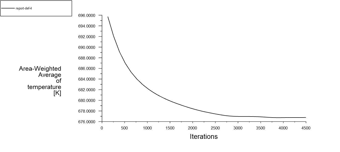
- One plot is created to know the average heat transfer coefficient and to understand the convergence.
- Hybrid initialization is opted for get a better guess of initial velocity and pressure field by solving the laplace equations.
- Checking the case and run the simulation for few iterations.
This procedure would be repeated for different mesh sizes.
Plots
Base Mesh:
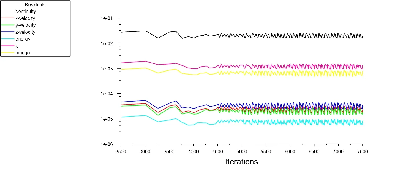
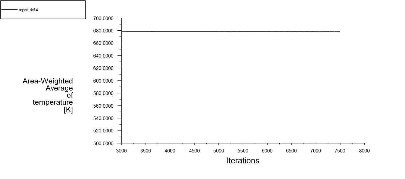
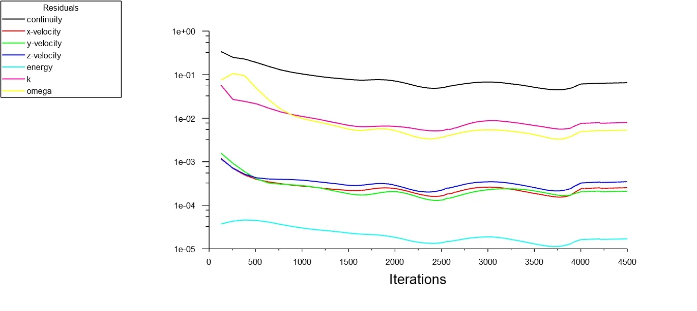
Medium size mesh:
Fine Mesh:
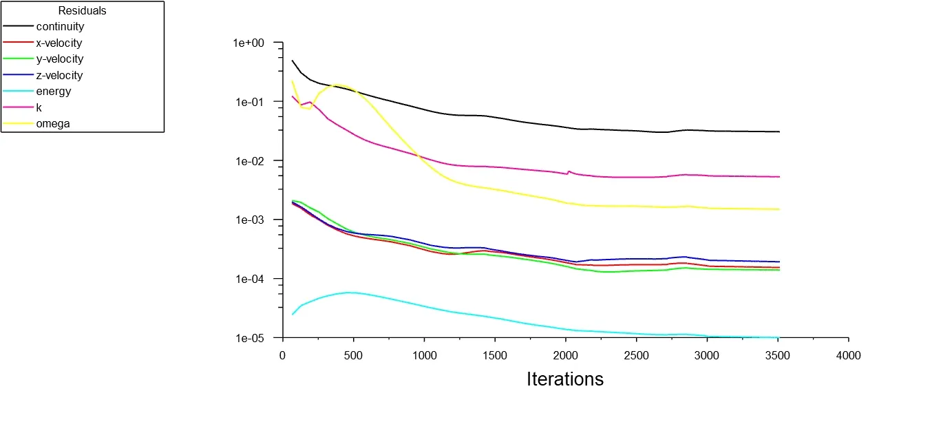
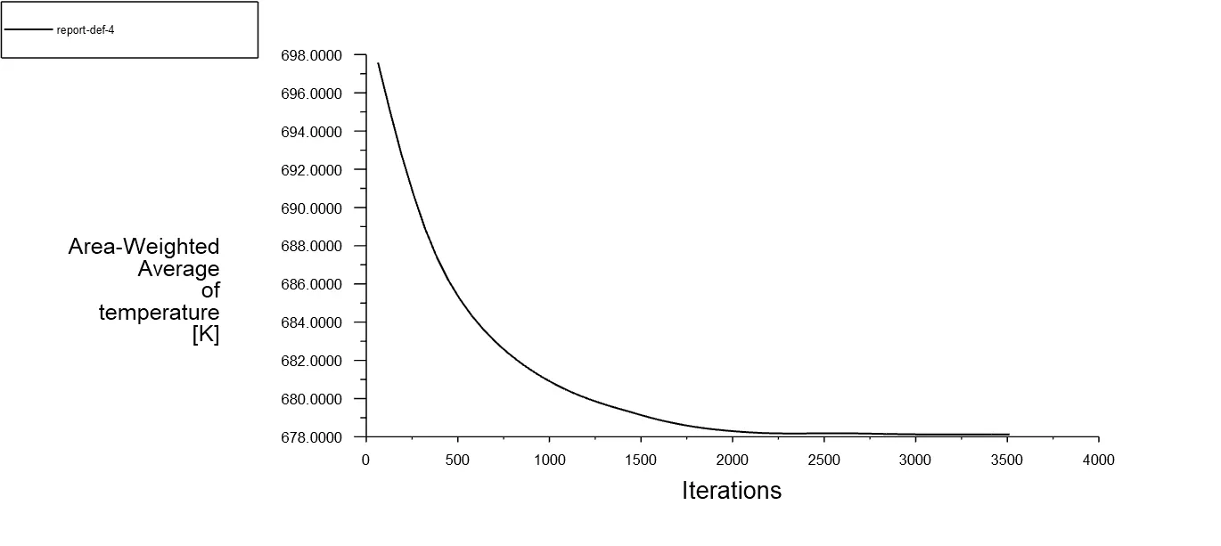
Heat Transfer coefficient:
There are several HTC measurement techniques.such that (i)Direct Method (ii)Transient method (iii) Wilson Method (iv)Heat/Momentum/mass Transfer analogy method (v)Boundary Layer thickness method (vi)Heat transfer coefficient probes method.
(i) Direct measurement of temperature and heat flux will give the Heat transfer coefficient based on the formula
`h=frac{q^'}{underset(s)(T)-underset(infty)(T)}`
(ii) Transient method is used for the unsteady boundary conditions for convection heat transfer.
The main advantage of the transient technique is the simplifcation of the experimental procedure, since temperature is the only variable needed to be registered along time.The transient thermal mathematical model can be of any complexity, from single lumped parameter to multidimensional transient systems solved by fnite-element techniques.The typical transient boundary conditions used in the experiments are bulk fuid temperate step change, plug fow andsquare-wave or sine-wave heat fux boundary condition.Parameters commonly used for the minimization between the mathematical model and the experimental data are maximum slope temperature derivatives, system thermal time constant, system thermal phase lag, system gain, frequency response and temperature curve ftting usually by least square methods.The transient response of the system can be modeled by the following equation as
`h=frac{-m.c}{underset(s)(A)}(frac{(dT)/dt}{T-underset(infty)(T)})`
(iii) Wilson method
The Wilson method or Wilson plot is a technique used to determine the heat transfer coefcient under conditions of more than one convective heat transfer process, e.g., heat exchangers. Its main advantage is it does not require direct measurements of surface temperature; only the fuids bulk temperatures are measured.
(iv)Heat,momentum and mass transfer analogy method
Analogies can be theoretically identifed by the analysis of energy, momentum and mass difusion equations under similar boundary conditions.Colburn showed by experiments that Reynolds analogy could be extended for situations where Pr and Sc numbers are not the same. It leads to the formulation of the Chilton–Colburn analogy [131], which is also called as extended Reynolds analogy.In general, the heat/mass/momentum transfer analogy can be demonstrated either by solving the conservation equations along the boundary layer, or by empirical expressions derived from experiments. In heat/mass transfer problems, experimental results can be correlated by expressions of the form:
`Nu=c*Re^m*Pr ^n`
`Nu-`Nusselt Number,Pr-prandtl number,Re-Reynolds number.
Sh=`c*Re^m*Sc^n`
Sc-schmidt number,Sh-Sherwood number.
(v)Boundary Layer thickness Method
In convective problems, the thermal boundary layer thickness can be used for the determination of local heat transfer coefficient.Observed that it is mostly used for laminar flow
`h=K/delta`
(vi)heat transfer coefficient probes method
some popular probes are Vitrac and Trystran [153] developed a small plane probe for HTC measurements in bulk fows or vicinity of planar or porous surface. The probe, Fig. 2, consists of a heating film sandwiched by two heat fux meters where thermocouples were installed over the external surface. A periodic heating was applied for unsteady measurements. The fluid bulk temperature could be measured by an initial temperature reading with no heating power applied to the probe.Pisters and Prakash [154] constructed a probe (Fig. 3) that used a heat flux sensor and a thermocouple mounted in the surface of an 11-mm brass cylinder to measure HTC in fuidized bed experiments. A cartridge resistance was used to heat the cylinder and a thermocouple to measure the air bulk temperature. With this probe, they could measure HTC in multiple positions of their experiment.
All the methods described above need to setup an experiment for the product.But heat/momentum/mass transfer analogy method provided an empirical relation based on the experimental data.So it would be the better method to validate the simulation results.For smooth pipes
Dittus boelter Equation
Nusselt number (Nu) =`0.023*Re^0.8*Pr^0.3`
Pr-Prandtl number-`frac{mu*underset(p)(C)}{K}`
K-thermal conductivity-0.0242 `W/(m*K)`
`underset(p)(C)-`specific Heat -1006.43 `J/(Kg*K)`
Pr-0.744
Nu-123.478
Nusselt number (Nu)=`frac{h*D}{K}`
Average Heat transfer coefficient (h)=`frac{Nu*K}{D}`
h=19.92 `frac{W}{m^2*K}`
Heat transfer coefficient depends on the factors such as density, viscosity, specific heat, thermal conductivity,bulk fluid velocity,surface geometry,nature of fluid motion(Laminar or turbulent flow).
- CAD model should be exact replica of the physical model.
- Geometry must share the information from the fluid volume to the solid wall
- Mesh should consist the inflation layers because gradients near the wall will be important for the pipes.Quality of the mesh is essentially important for each and every geometry.
- Mainly aspect ratio should be near 1 and skewness should be near 0.
- Mesh should be refined to achieve the better quality.
- Need to choose the proper solver and entering the precision values for the material properties.
- Applying the exact boundary conditions and material assigned for the cell zones.
- Temperature value entered at reference values task window should be exact.
Following the above points will improve the accuracy for the predictions on simulations.
Conclusion:
1.The following table provides the observed data from the simulation.
| S.No | No of elements | surface Avg Heat transfer coefficient in `W/(m^2 K)` from fluid Volume | Analytical Heat transfer coefficient in `W/{m^2.k` |
| 1 | 136626 | 26.32 | 19.92 |
| 2 | 419868 | 28.82 | 19.92 |
| 3 | 499255 | 26.09 | 19.92 |
Data provides simulation contains the error of 31% this contains the error related to validation studies and simulation part.Error regards to simulation part araises from meshing,numerical errors etc.
Sign of the avg heat transfer coefficient comes from heat flux of the simulation.
It is clear that average heat transfer coefficient needs much finer meshes and the empirical relation doesnot indicates sign.The experimental data never provides a sign to the heat transfer coefficient.
2.Velocities present at the center plane of the fluid volume as shown below
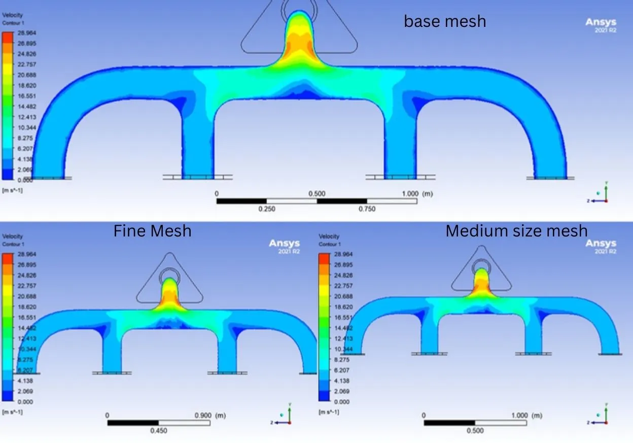
Difference between them is capturing a no slip region and the four branched pipes joining location.This shows clearly the velocity raise at the location joining by the branched pipes.At converging location,due the curvature the moving air doesnot able to occupy the location near the wall.
3. Pressure on the center of the fluid volume is depicted below
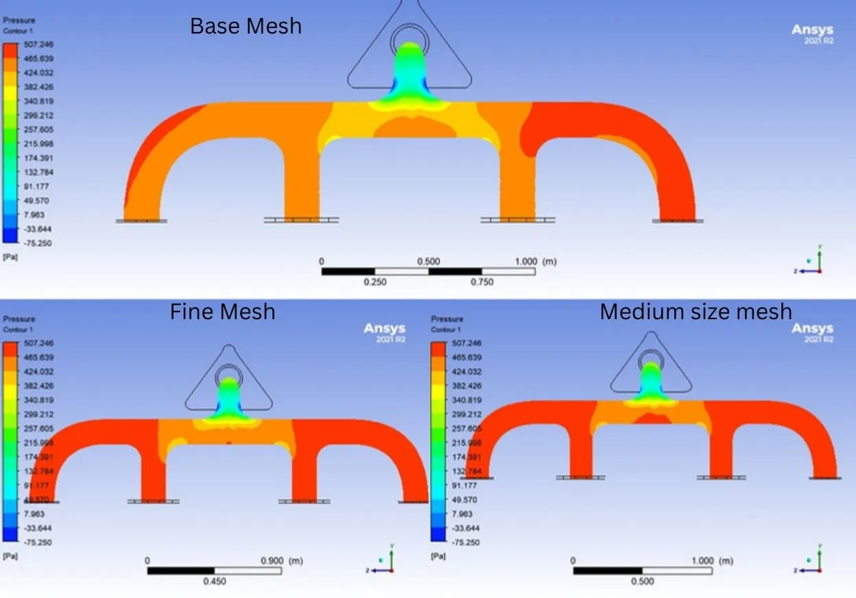
Pressure is high at the inlets and low at the converging location and starts decreasing the pressure as air passing through the outlet.The reason for decreasing pressure is to transport the air through the small area.
By observing the velocity and pressure,the pressure decreases with velocity increases.
4.Temperature at the centerplane of the fluid volume is depicted below
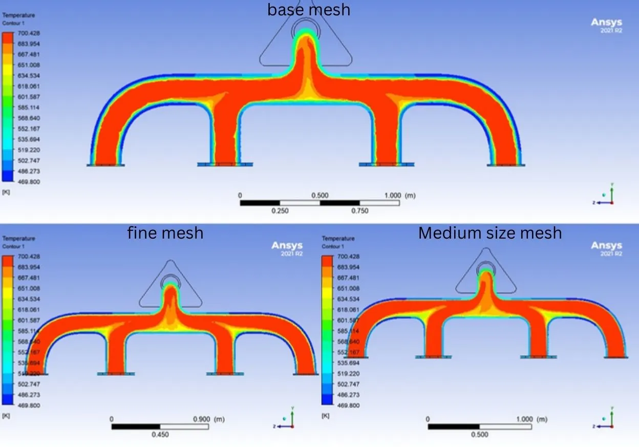
Temperature is low near walls and at converging section of four branched pipes and at the center of the pipe as high as inlet.
5.Streamline is one of the visualisation technique employed for visualising the path of the imaginary particle suspended on the fluid volume.
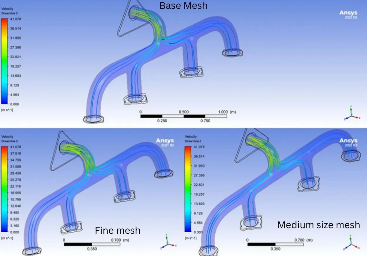
Streamlines are a family of curves whose tangent vectors constitute the velocity vector field of the flow. These show the direction in which a massless fluid element will travel at any point in time.streamline will allow us to learn about the imaginary fluid particle moving in the direction and quantity (variable can be applied for the stream line) of velocity.While observing the path the none moving air occupied at the place of joining the four branched pipes very clearly.
6.Surface Heat transfer coefficient for three different mesh sizes depicted below
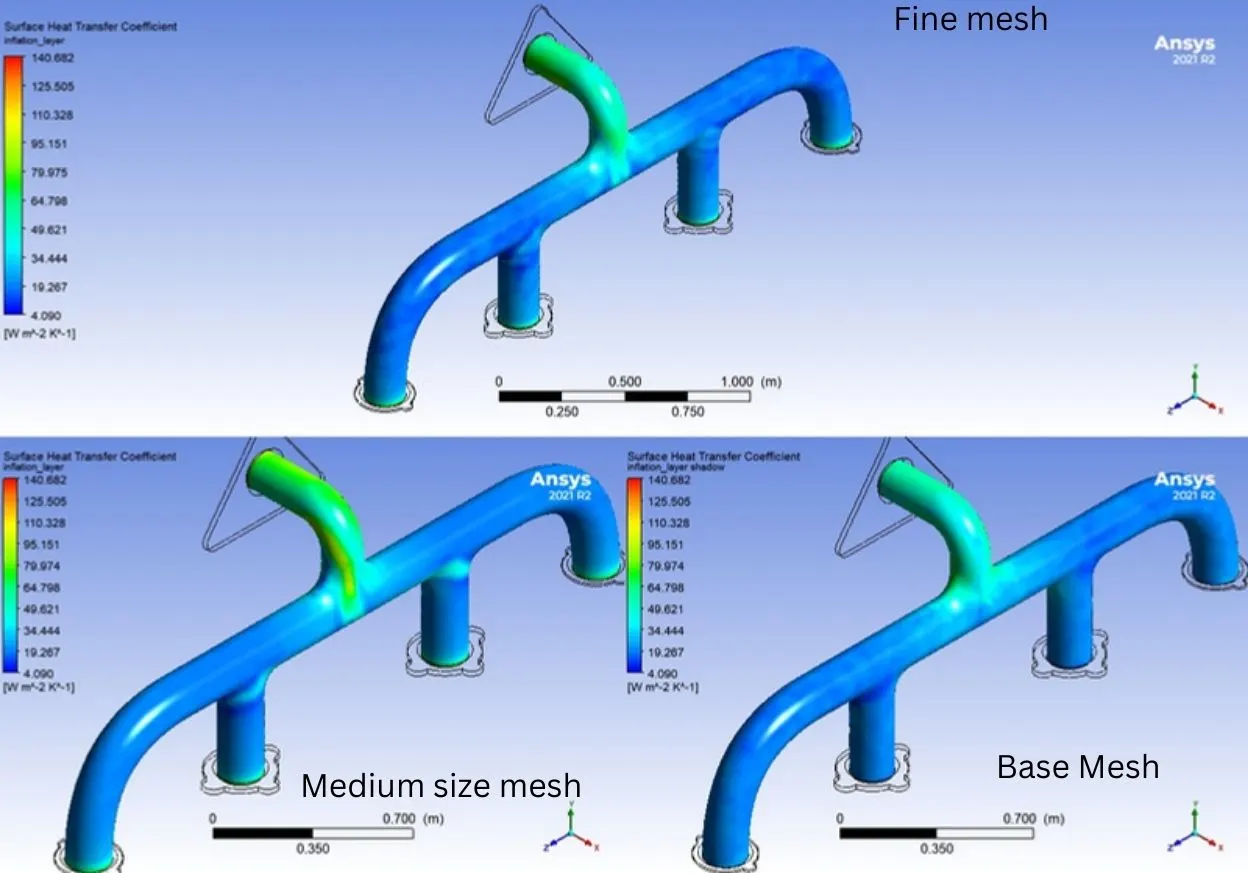
Heat transfer coefficient depends greatly on the temperature difference.At the converging from brached pipes and outlet has a greater heat transfer coefficient
References:
1.Comparative Study between Curved and Straight Pipe Heat Exchanger Using Solid Works., Mohamed F. Al-Dawody,Dhafer A. Hamzah
2.Fluid Mechanics fundamentals and its applications ,Fourth edition,Yunus A.Cengel and John M.cimbala
3.Heat and mass transfer fundamentals and its applications,sixth edition,Yunus A.Cengel and Afshin J.Ghajar
4.Heat transfer coefficient:a reciew of measurement techniques,Journal of brazilian society of mechanical sciences and Engineering...,Tiago Augusto Moreira,Alex Roger Almeida colmanetti,cristiano Bigonha Tibirica.