Week 4 - CHT Analysis on Exhaust port
Aim:To study Conjugate Heat Transfer Analysis of Exhaust port using ANSYS Fluent.
Objecttives:
- Simulation of conjugate heat transfer on exhaust manifold.
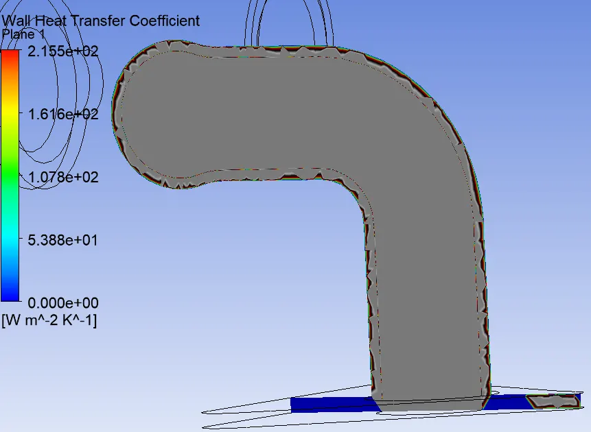
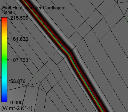
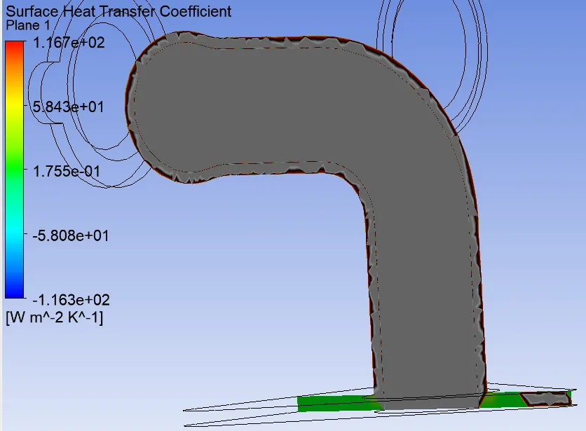
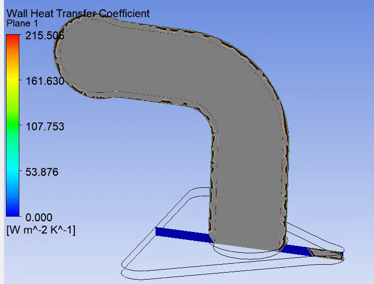
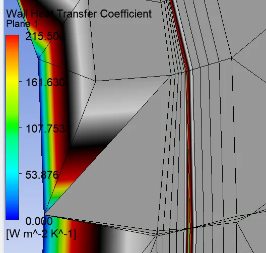
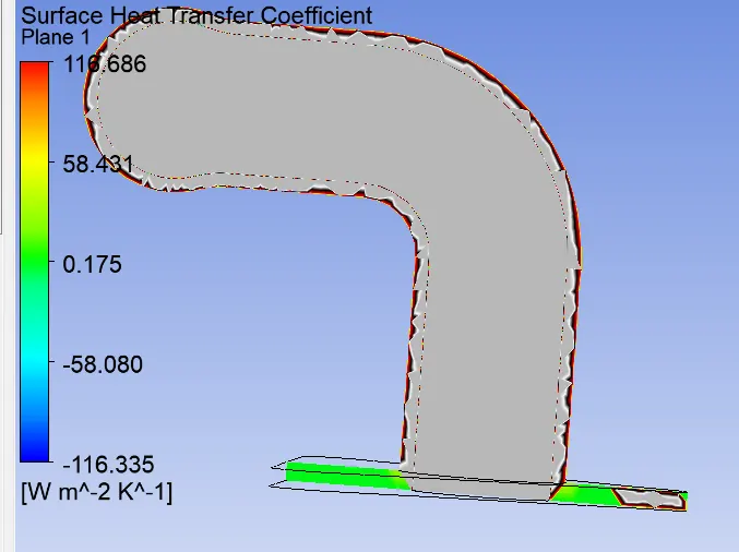
- Calculation of wall heat transfer coefficient on internal solid surface.
- Maintaning appropriate Y+ value for the turbulence modal.
Conjugate Heat Transfer(CHT):
The Conjugate Heat transfer(CHT) analysis type allows for the simulation of hate transfer between solid and fluid domain by exchanging thermal energy at the interference between them. A tyipical application of this analysis type exists as but is not limited to the simulation of heat exchangers, cooling of electronic equipment, and general-purpose cooling and heating system.
The contemporary conjugate convective heat trnsfer modal was developed after computers came into wide use in order to substitute the empirical relations of proportionality of heat flux to temperature difference with heat transfer coefficient which was the only tool in theoretical heat convenction since the time of Newton. This modal based on strictly mathematically stated problem describes the heat transfer between a body and fluid flowing over or inside it as aresult of the interaction of two objects. The physical processes and solutions of the governing equation are considered separatly for each object in two subdomains. Matching conditions for these solutions at the interface provide the distributions of temperature and heat flux along with the body flow interface, eliminating the need for a heat transfer coefficient.
Why CHT analysis is used:
CFD and more specifically CHT analysis can accurately predict heat transfer by simultaneously solving all the relevent solid and flow field heat transfer processes, for e.g, conduction through solids, free and froced convention in the gases/ fluids, and thermal radiation.
The CHT approach has an advantage over Finite element thermal analysis in that wall heat tranfer coefficients and their local variations on surfaces are directly calculated within the model rather than bassed on simplified empirical calculations. The CHT approach, therefore, has benefits for these applications where heat transfer is either non-uniform or difficult to calculate empirically.
Where is CHT analysis used:
Starting from simple example in 1960s, the CHT method has becomes a more powerful tool for modeling and investigating natural phenomenon and engineering system in different areas ranging from aerospce and nuclear reactions to thermal goods treatment and food processing, from the complex procedure in medicine to atmosphere/ocean thermal interaction in metrology, and from relatively simple units to multistage, nonlinear processes.
Applications
- Internal combustion Engine
- Electromobility
- Pumps and Compressor
Geometry Set-up:
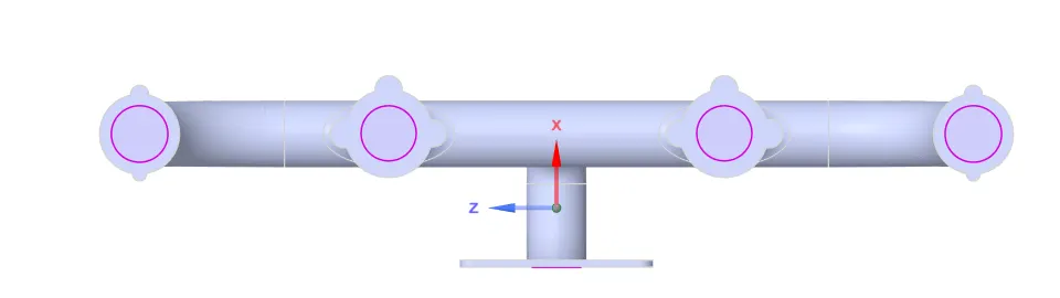
- Load the model into SpaceClaim and change the units into meters.
- Remove the duplicate edges in the model.
- Then extract the fluid volume and given the name inner volume as fluid volume as solid and remove the empty component.
- Enable the shared topology of the main component so that the mesh and physics can be shared conformal mesh can be achieved.
- Lastly, to achive conjugate heat transfer between the fluid and wall we have to choosw share prep under the workbench tool so that heat transfer is captured throughout the wall from inlet and outlet.
Mesh Set-up:
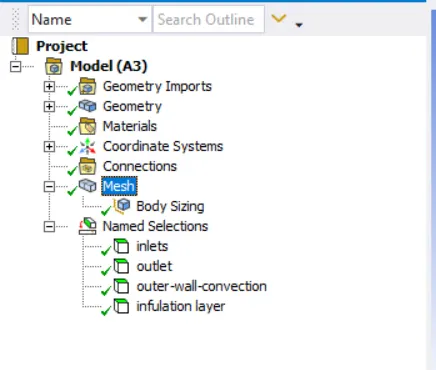
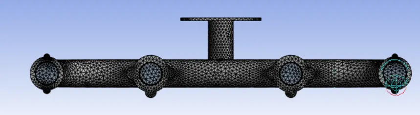
- Select the faces and name the accordingly.
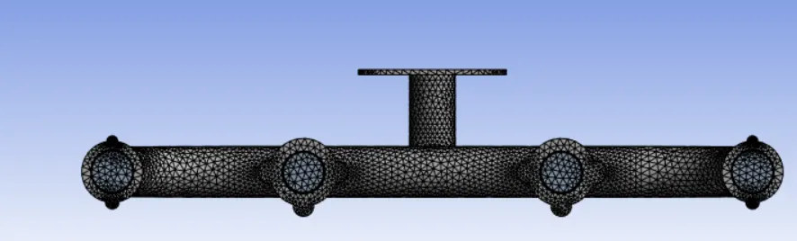
- Create the name selection for fluid volume so that the inflation layer can be achieved on the body since CHT is beetween fluid volume and solid volume.
- Using sizing option and hide the outer solid volume and select the volume we create generating the finite mesh to the system.
Simulation set-up:
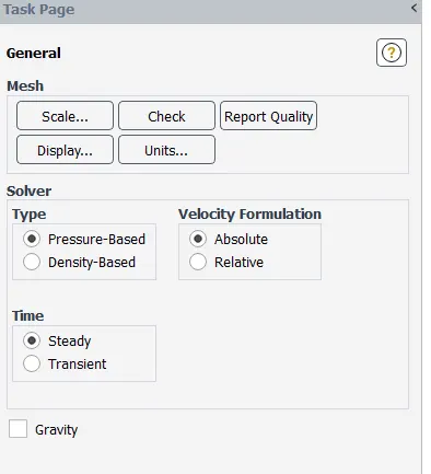
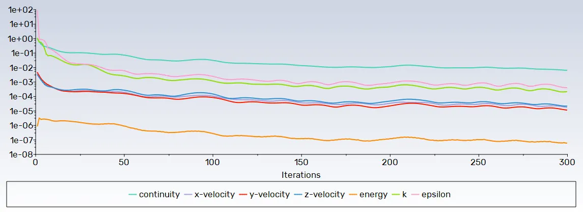
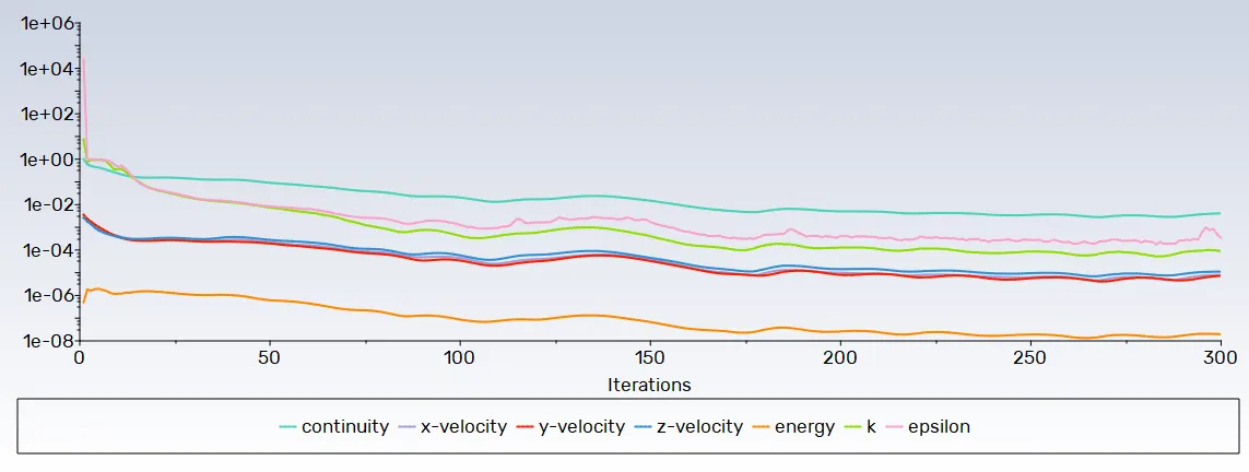
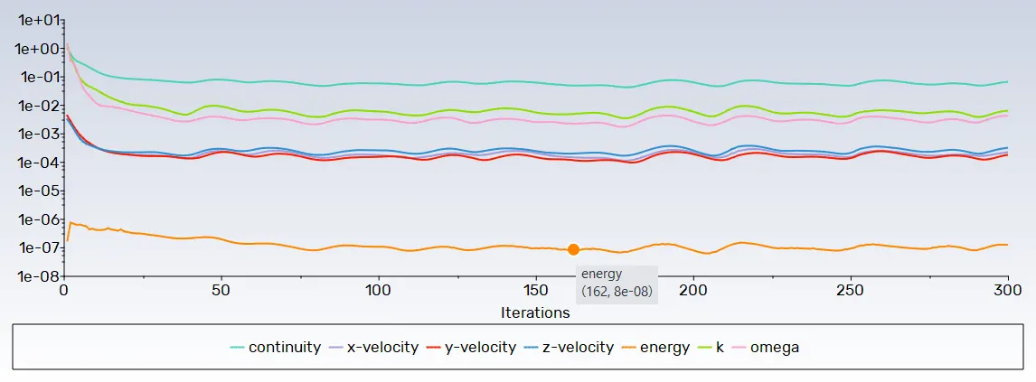
- The simulation will be carried out using pressure based solver with stedy state condition.
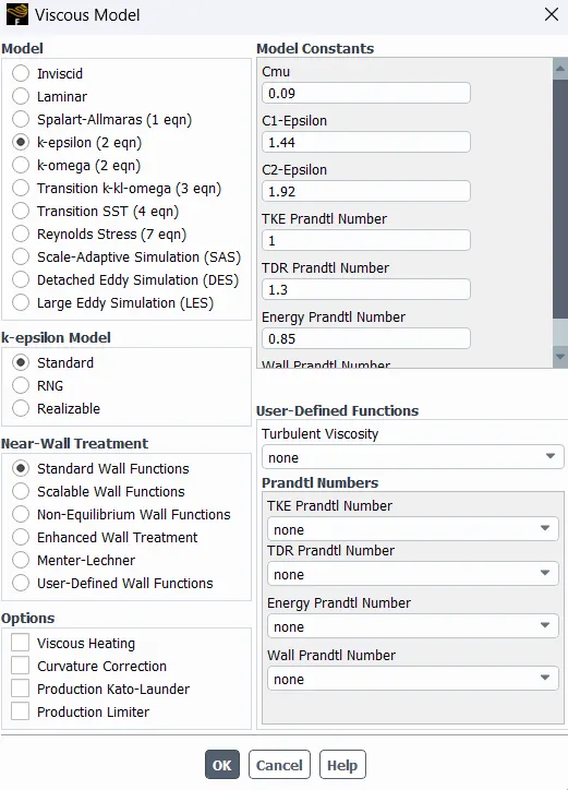
- K-Epsilon with standard near wall tratment option has been selected from viscous model dialogue box. Energy eqution has been turned on for this simulation.
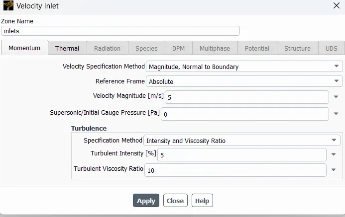
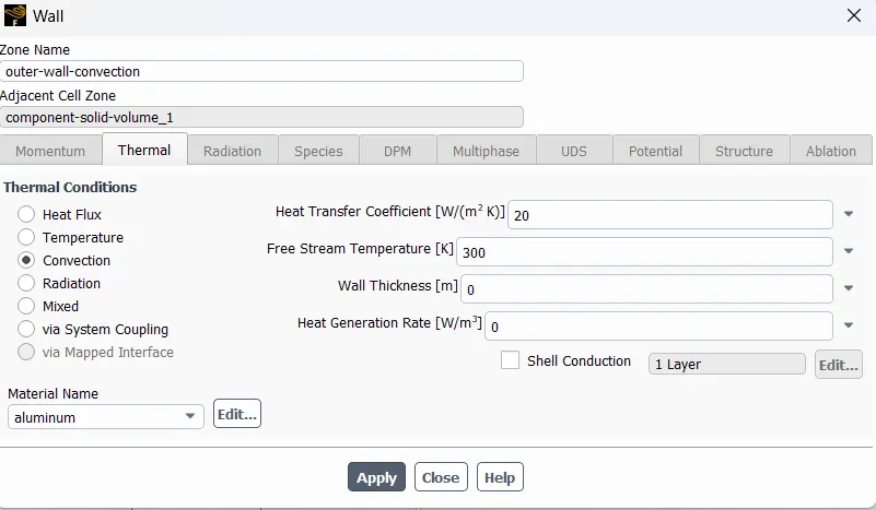
- After completing the visscous to check the fluent air and solid to be aluminium.Open the boundarie condition inlet to select and giving the velocity is 5 and temperature is 700K.
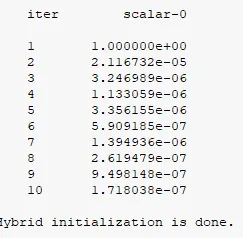
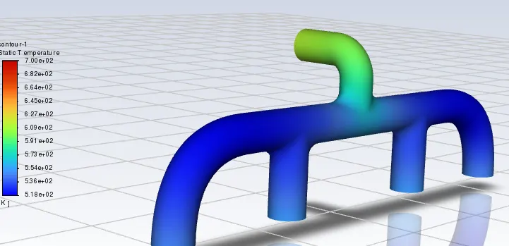
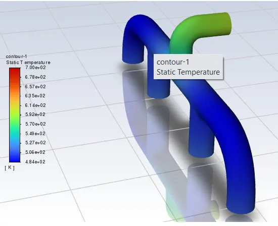
- Hybrid intillization to intilizing. Go to resutls and contours to set the temeprature create in the inlet,outlet and outer wall.

Results:
Case 1:
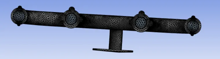
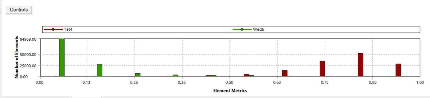
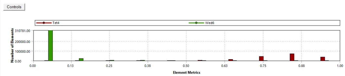
Element size:150mm
Sizing element size:50mm
No. of element:249836
Visccous model:k-epsillon
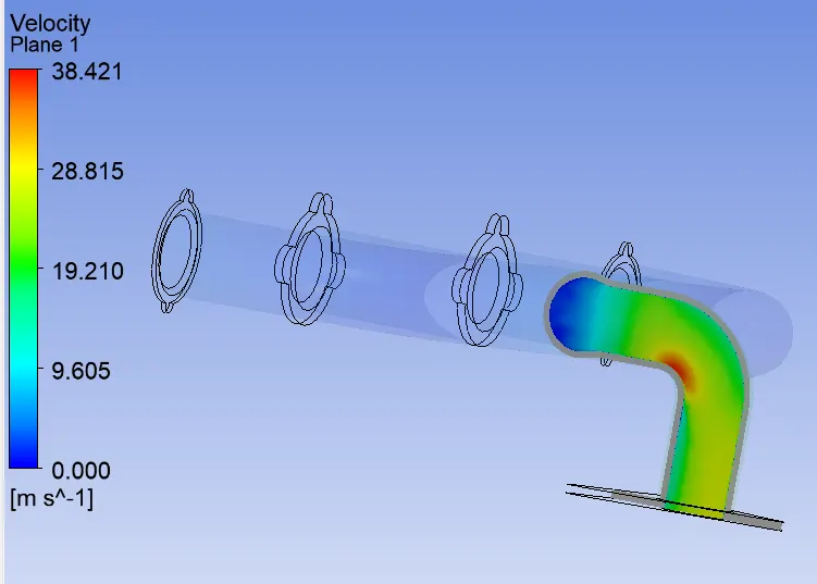
Inlet velocity:5 m/s
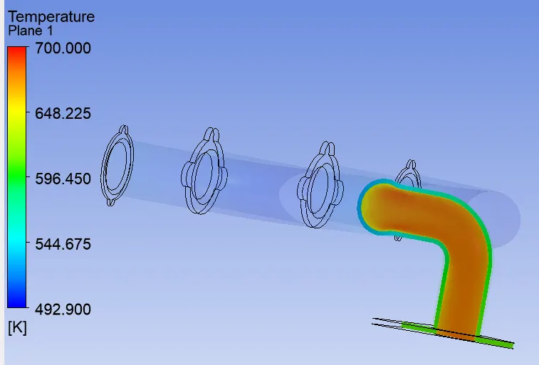
Inlet temperature:700k
Heat transfer coefficient:20W/m^2K
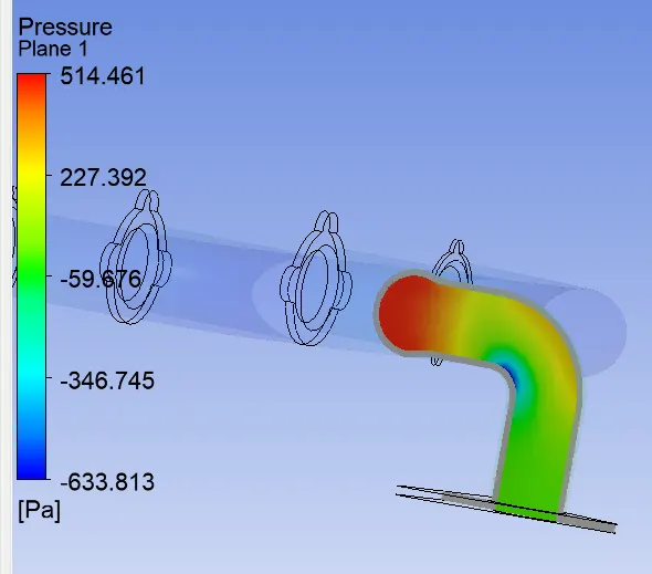
Case 2:
Element size:100mm
Sizing element size:35mm
No. of element:239927
Visccous model:k-epsillon
Inlet velocity:5 m/s
Inlet temperature:700k
Heat transfer coefficient:20W/m^2K
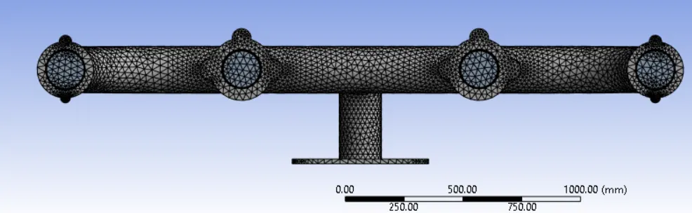
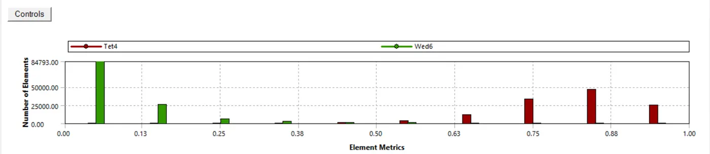
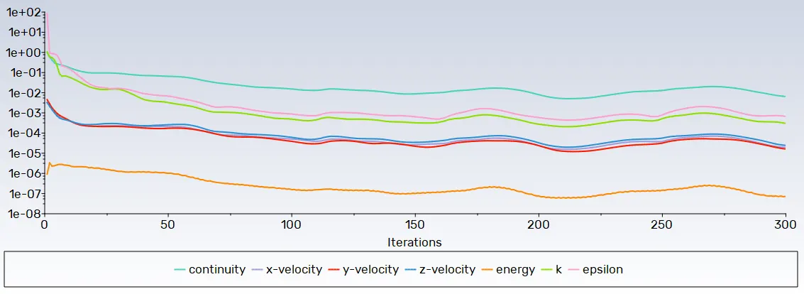
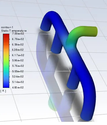
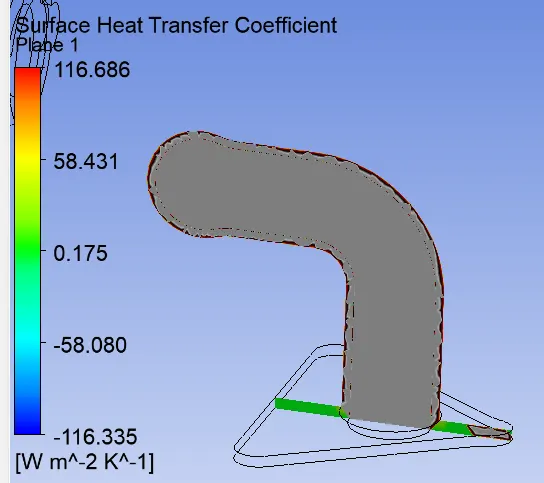
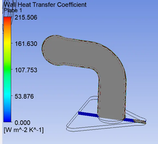
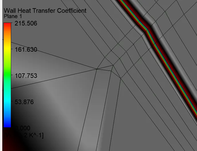
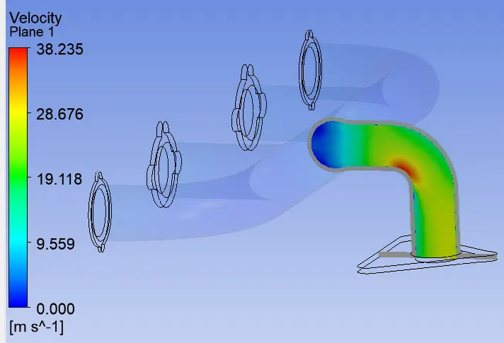
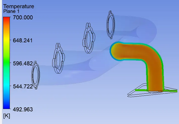
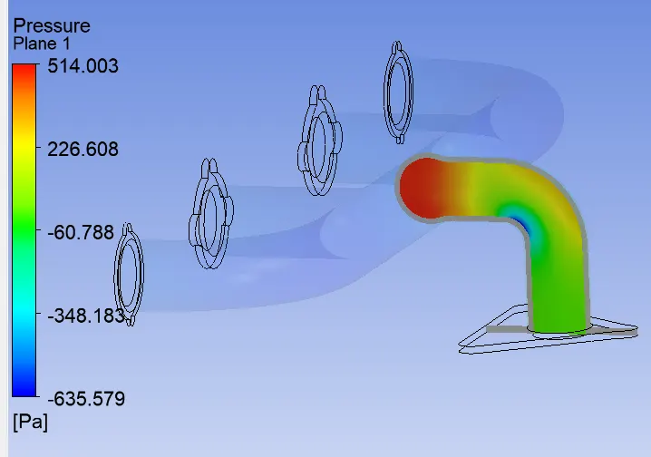
Case 3:
Element size:75mm
Sizing element size:20mm
No. of element:502694
Visccous model:k-epsillon
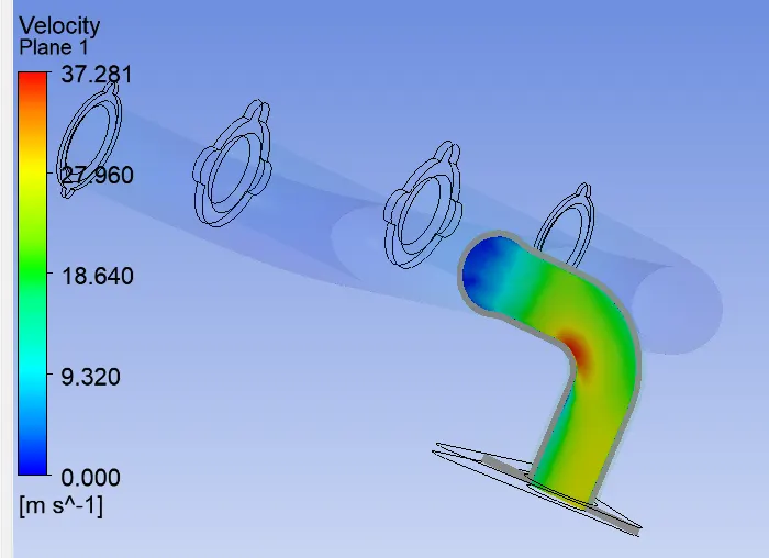
Inlet velocity:5 m/s
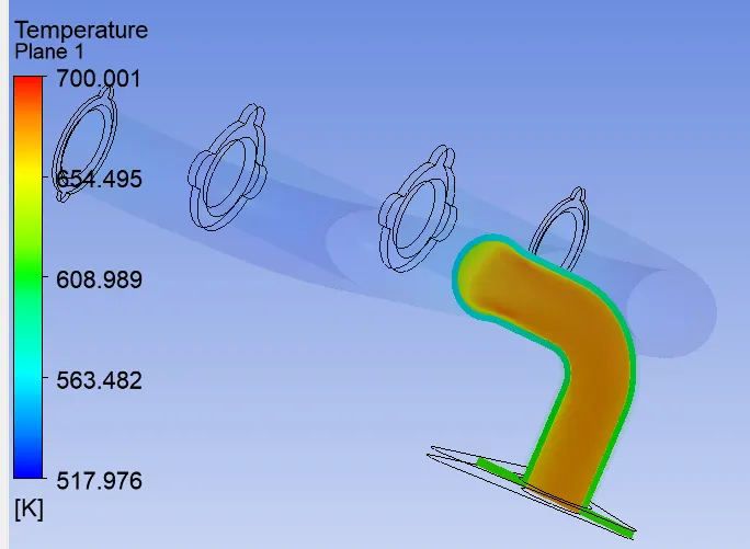
Inlet temperature:700k
Heat transfer coefficient:20W/m^2K
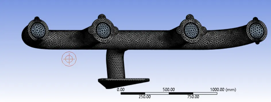
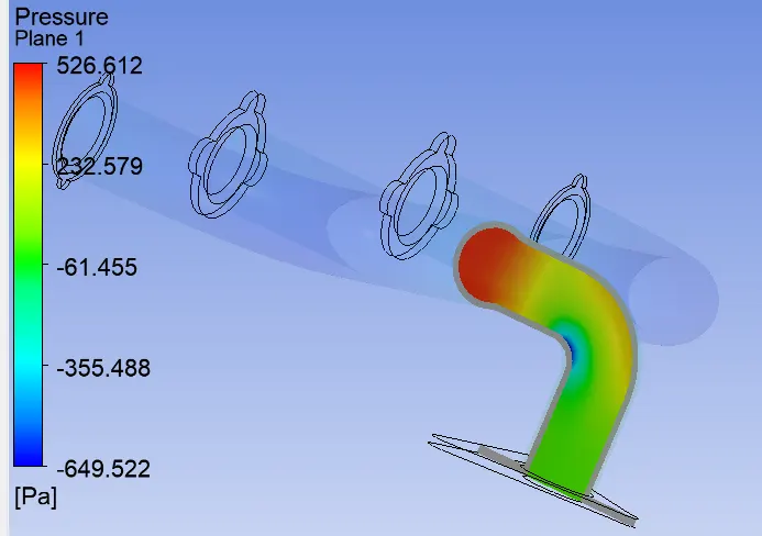
Case 3:
Element size:75mm
Sizing element size:35mm
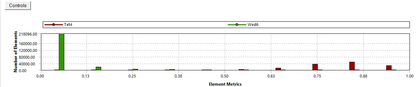
No. of element:360825
Visccous model:k-epsillon
Inlet velocity:5 m/s
Inlet temperature:700k
Heat transfer coefficient:20W/m^2K
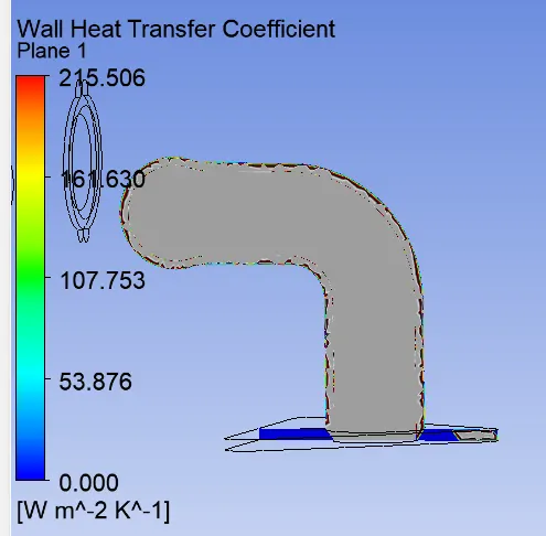
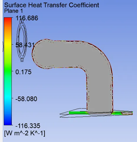
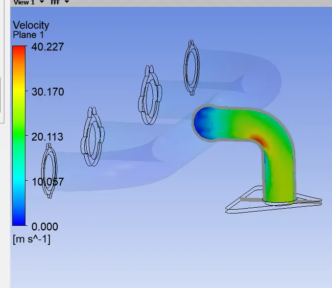
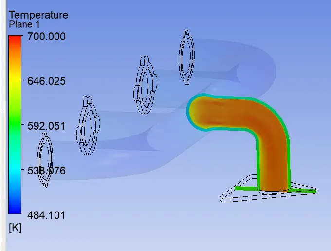
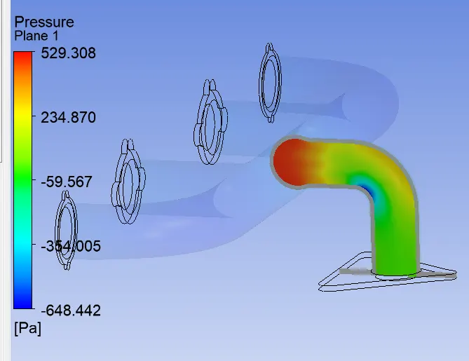
Nusselt number is given by
Where:
D is the inside diameter of circular duct
Pr is the prandtl number
n=0.4 for the fluid being heated, and n=0.3 for the fluid being cooled.
Nu=Nusselt's number
Re=Renold's number
Nu=0.023.56816.53^0.8.0.71=127.58
h=Nu.K/L=127.58.0.024/0.1666=18.6 W/m^2.K
We know that the Nusselt's number is a function of Reynold's number, Which in tuen is function of flow velocity.
Therfore,HTc is directly proportional to flow velocity.
So, the heat transfer coefficient consider for the simulation, which is 20 W/m^2.K, is very near by the calculated heat transfer coefficient. The calculated Nusselt Number's value depends on the Prandtle number & Reynolds number.And also, the Dittus-Boeltlr equation is accurate for the smooth circular pipe with small to moderate temperature difference and it is less accurate for rough pipes & large temperaturee variations. Because of these factors, the difference in the caculated heat transfer coefficient & coefficient consider for simulation is acceptable.
Canclusion:
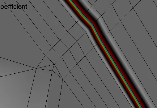
From the base line mesh which doesn't have inflation layer and from the refined mesh we can conclude that the model with inflation layer can trap better wall adjacent values and conditions. Thus it signifies the importance of the inflation layer in capturing near-wall Phenomenons.
As a fact we know that finer the mesh accurate the values are. The viscous models and solvers should be choosen according to the requirements.A good understanding of solvers and models is needed for CHT analysis.
Y pluse value should be maintained depending on the solvers. Comparing the contours of temperature between the baseline mesh and refined mesh, we have observed that temperature is more accurate in case of refined mesh with an inflation layer.