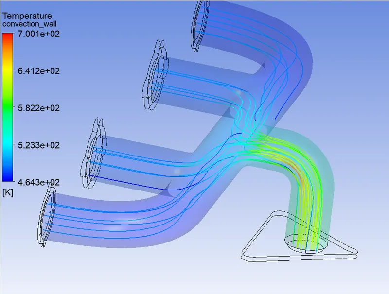
Week 4 - CHT Analysis on Exhaust port
AIM
To perform CHT analysis on Exhaust Port and validate the results
CONJUGATE HEAT TRANSFER ANALYSIS
Conjugate heat transfer is the combination of transfer of heat in solids and fluids by conduction,convection and radiation as well if necessary. In the exhaust port simulation the hot air enters through inlet port and the heat is transferred due to convection by the air (fluid) as well as conduction through the pipe (solid)
CHT analysis is used for heat exchangers, cooling of lithium ion cell, cooling of electrical components such as graphics card etc.
Y+ Value for k-epsilon Model
The non-dimensional parameter for determining proximity to a wall is Y+. It is used to provide the height of the first grid element near to a wall in a CFD simulation. A fluid flowing across a flat plate has several layers. Due to the no slip condition, the layer close to the wall is affected by shear stress the most. The presence of the plate has a greater impact on the layers close to the wall. For capturing the near-wall layers, the size of the grid near the wall plays an important role. It needs finer mesh in the region close to the wall to capture the effects of the wall. For k-epsilon model, standard wall treatment is used to capture the boundry layer physics, due to which maintaining a Y+>30 is recommended.
GEOMETRY
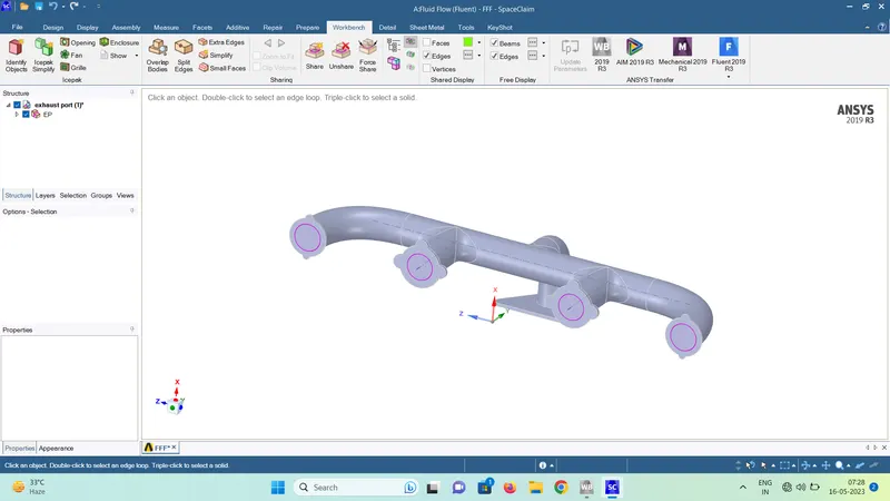
- The exhaust port file is imported in spaceclaim
- Volume of the exhaust port is extracted using volume extract option
- For CHT analysis, a conformal mesh in the solid fluid interface is necessary. For this share topology is enabled and the shared surfaces are selected using share prep
MESH
Two cases of mesh are studied
CASE-1 : Baseline Mesh
CASE-2 : Refined Mesh
CASE-1
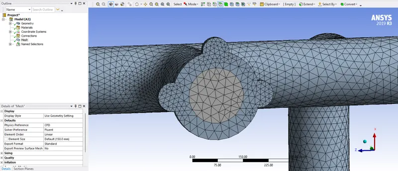
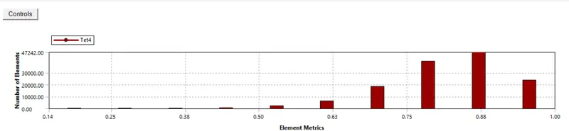
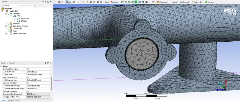
- For the baseline mesh, the mesh is auto-generated at Element size = 150 mm
- Conformal mesh formation can be seen in the baseline mesh
CASE-2
- For the refined mesh, the whole body is meshed at an Element size of 50 mm
- Inflation layers are added to the fluid-solid interface with Total Thickness=5mm
SET-UP
The same set-up is run for both the mesh cases
Model : k-epsilon (standard wall function)
Energy : ON
Solver : Pressure Based
Inlet Velocity : 5 m/s
Inlet Temperature : 700 K
Outer- wall Heat Transfer Mode : Convection
Outer- wall HTC : 20 W/m^2.K
RESULTS
CASE-1
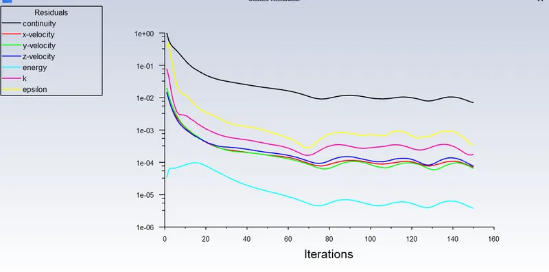
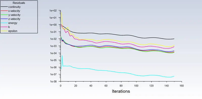
RESIDUALS
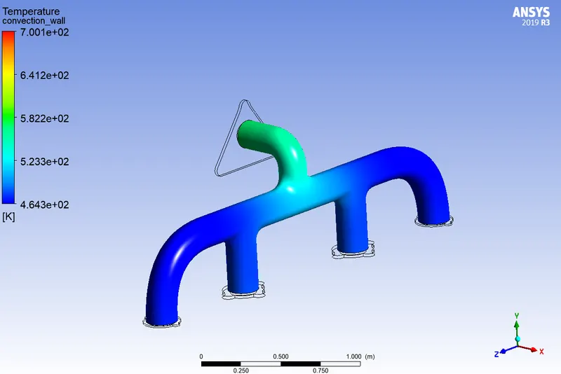
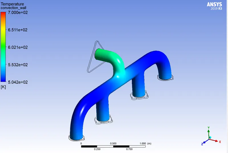
TEMPERATURE CONTOUR
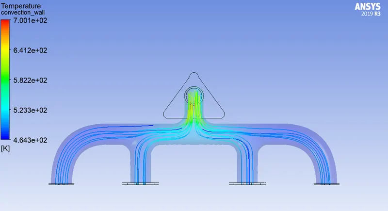
VELOCITY STREAMLINES
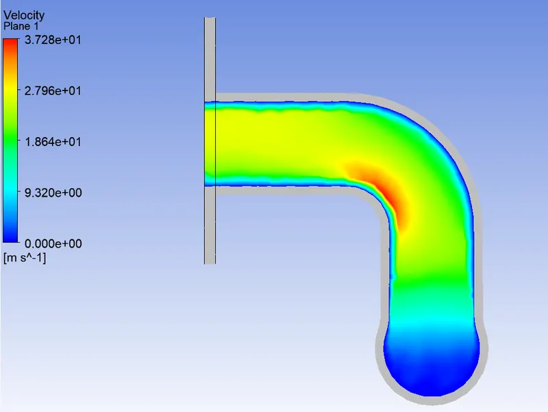
VELOCITY CONTOUR
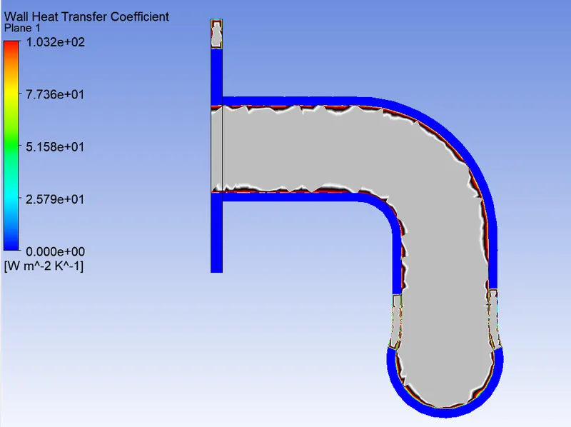
WALL HEAT TRANSFER COEFFICIENT
CASE-2
RESIDUALS
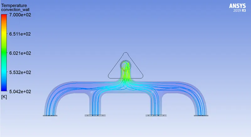
TEMPERATURE CONTOUR
VELOCITY STREAMLINES
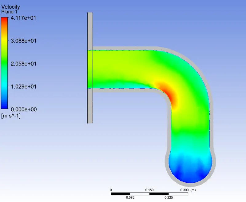
VELOCITY CONTOUR
WALL HEAT TRANSFER COEFFICIENT
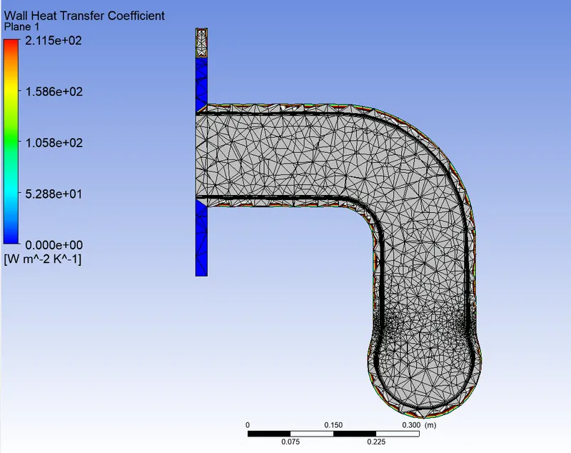
| MESH | No. of Nodes | No. of Elements | Heat Transfer Coeff. |
| Baseline | 27519 | 138082 | 103.2 |
| Refined | 84934 | 238414 | 211.5 |
VALIDATION
- The Nusselt number is the ratio of convective to conductive heat transfer across a boundary.

- where h is the convective heat transfer coefficient of the flow, L is the characteristic length, k is the thermal conductivity of the fluid.
- Then this Nusselt number is related to Reynolds number i.e.,

- This shows that heat transfer coeffcient is directly proportional to the reynolds number and which is proportional to velocity. In the plot it can be observed that the point where the velocity is maximum, is where the value of heat transfer coeffcient is also maximum
CONCLUSION
- It is important to use conformal mesh for Conjugate heat tramsfer analysis
- Use of share topology to get a conformal mesh is necessary
- Adding inflation layers to the mesh as HTC is associated to the first element of the
- Heat transfer coefficient depends on the velocity of the fluid or Reynolds number.
Accuracy of the simulation depends on various factors
- The quality of the mesh
- Near wall treatment or model used
- Conformal mesh