Week 4 - CHT Analysis on Exhaust port
Aim:
CHT - conjugate heat transfer, where the heat is transfered between solid and fluid domain.This type of analysis is mostly used to increase the efficiency of the cooler in the automobile application , heat exchangers of power plant and heaters. In this analysis the convective heat transfer is achieved.This application is widely used because the combination of different medium is practical application.The fluid flows between the solids the results will be replicated based on the material properties , physical properties, heat tranfer co efficient.
In this experiment the exhaust manifold is undergo CHT analysis.
Procedure:
1) Import the file and clear the extra edges.
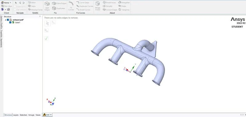
2) extract the volume (i.e) both fluid volume and solid volume
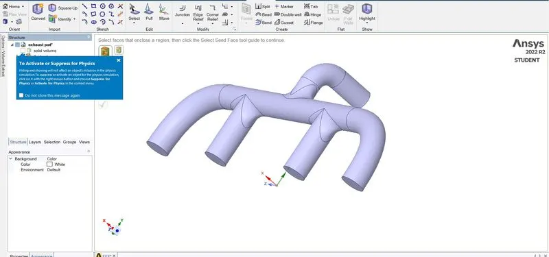
3) share the topology so that the edges share with each other and edges get equal mesh. The topology sharing is identified by pink colour.
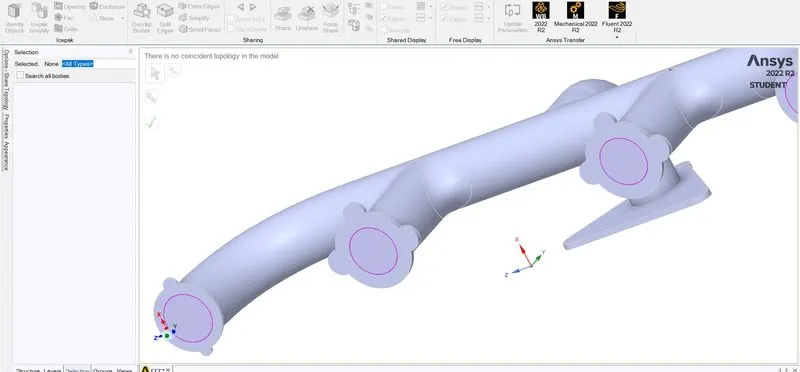
4) Close the geometry and open mesh generate general mesh run.
5) Naming is given and create the inflation layer over the fluid volume.
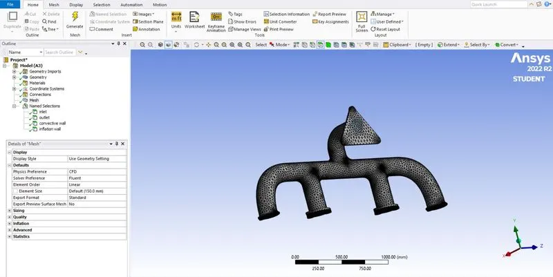
6) Here both the solid and liquid volume is kept active.
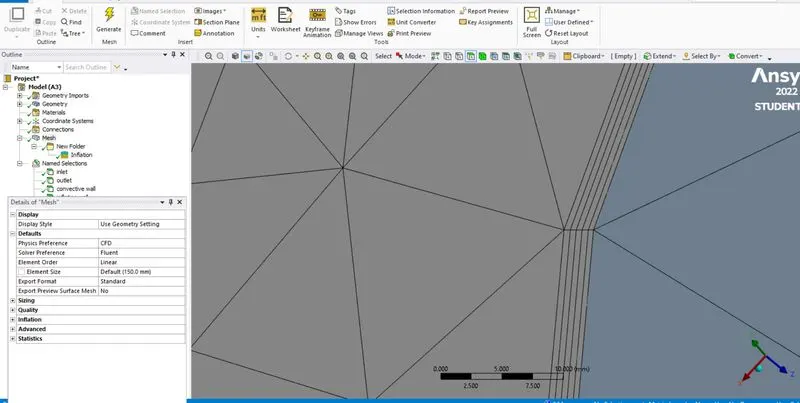
7) Once the mesh is done the fluent set up is done.
Steady state--> pressure based --> energy equation (open) --> viscous (K- omega) --> material ( Fluid --> air), ( Solid --> aluminium) --> Check cell zones fluid and solid zones --> setup boundaries --> Inlet ( initial velocity (5m/s), Temperature (700k) ) --> For convective wall ( Heat transfer co efficient 20(W/m^2K)--> Create the residuals --> report for Heat transfer co efficient.
8) Residual report --> contour report for temperature and velocity --> contour report for heat transfer co effi--> Animation is created.
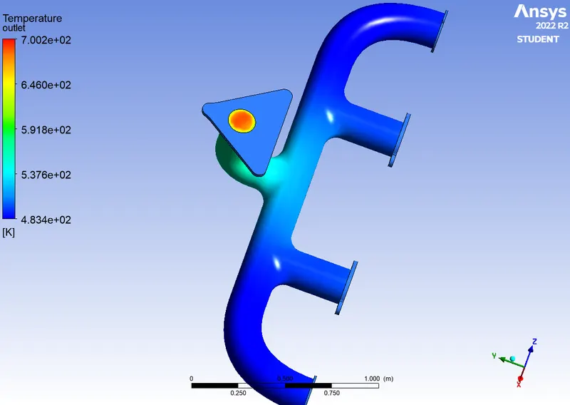
Temperature at outlet area.
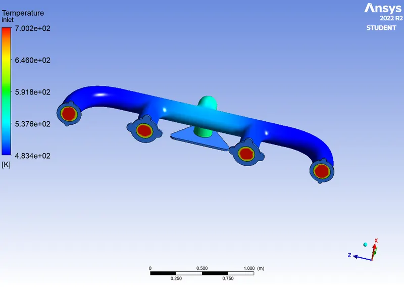
Temperature at inlet area
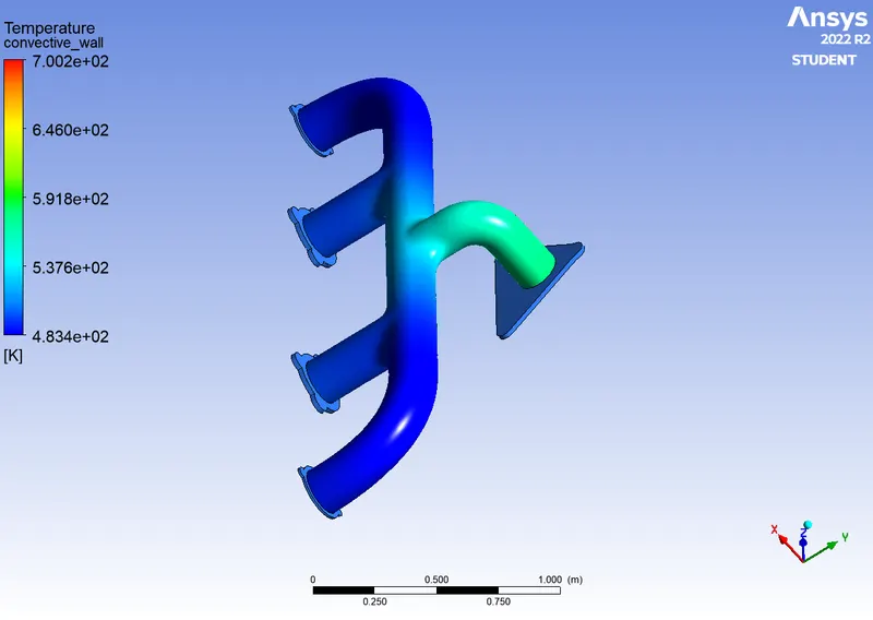
Temperature at inflation layer or convective wall:
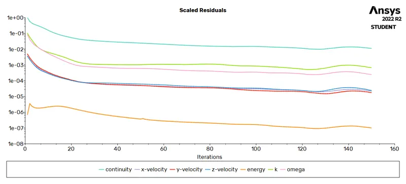
Residual plot for 150 mm target length
9) Final Post processing will be done.
The case 2 in which the mesh target length is decreased to 100 mm where the same result is analysed.
The Same procedure will be followed for the target length of 100mm and the results are here:
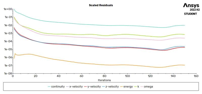
The residual :
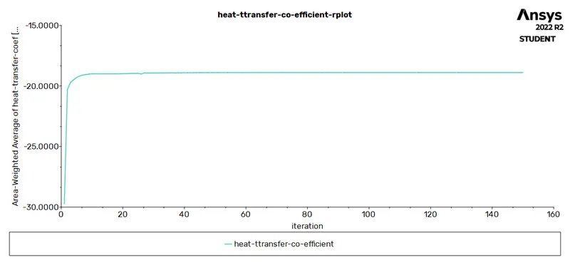
Heat transfer co efficient :
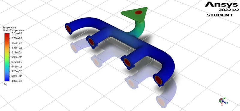
Temperature contour:
Velocity contour:
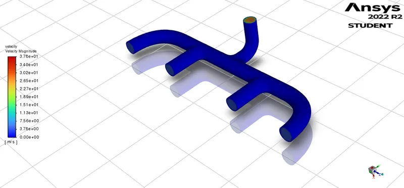
10) Then by comparing with the analytical results will be done to intrepret.
Temperature contour in plane view :
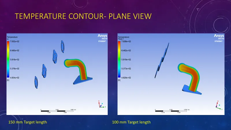
This clearly shows the raise in temperature at the convective wall layer.
Velocity contour in plane view:
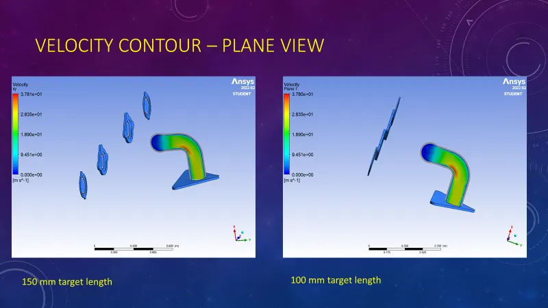
In this the velocity is raise in the bend area according to the flow.
Heat transfer co efficient for the 150 mm target length is 47.244 W/(m^2 K)
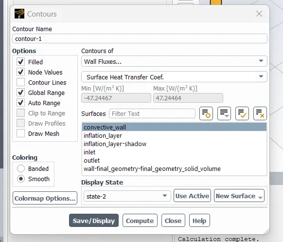
Heat transfer co efficient of 100 mm target length is 46.838 and by area weighted average it is found that

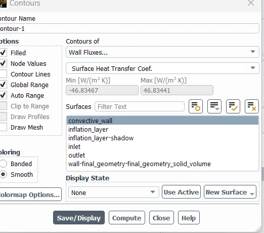
Heat transfer co efficient plot for both 100mm:
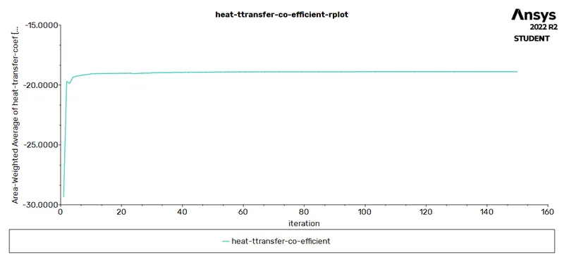
Heat transfer co efficient plot for 150 mm :
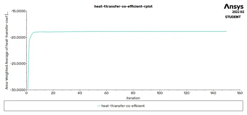
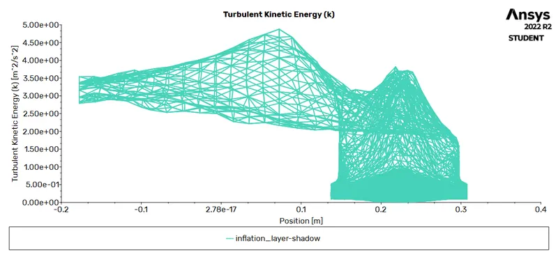
Turbulence plot for y plus :
150mm target length :
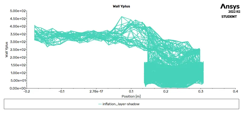
100mm target length :
The y plus layer is found in y plus calculator. the general formula to calculate y plus is
HTC prediction :
y = yplus*μ /μo*ρ
μo=square root of (wall shear stress / density ) .
wall shear stress = skin friction co efficient *0.5ρ*U^2
Heat transfer co efficient can be identified analytically based on Nusselt number .
Nusselt number is ratio of convective heat transfer to conductive heat transfer
Emprical relation of nusselt , prandltl and reynolds numbe for convection heat transfer is

Based on this the numerical and anlytical can be analysed.
link :
https://drive.google.com/file/d/126BAwZm8-lRMswDEPBYEPI8B4TOjcHtE/view?usp=share_link