Week 2 Challenge : Surface meshing on a Pressure valve
Aim :
To get practice with the given model(in this case valve) by checking its geometrical errors and perform topology clean up.
Given:
Target length : 1mm, 3mm, 5mm
element type: tria
Methodology:
1. Import the geometrical file.
2. Deleting or filling the rough geometry into full structured geometry to mesh.
3. Geometry check and Penetration checks.
4. Mesh the geometry for the targeted length and element type.
5. Measure the nodal surface distance.
6. Save the geometry accordingly.
Explanation:
1. Import the geometrical file.
FILE ----> OPEN ----> Import the geometry.
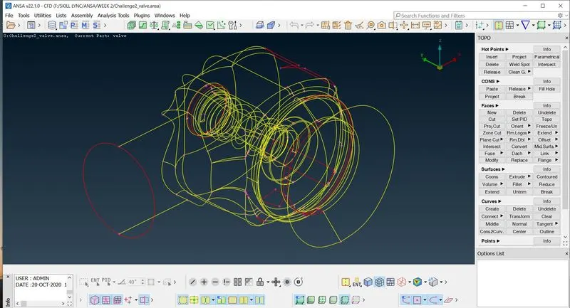
As it is a wire frame structure change into model by clicking shadow icon on the bottom of the screen.
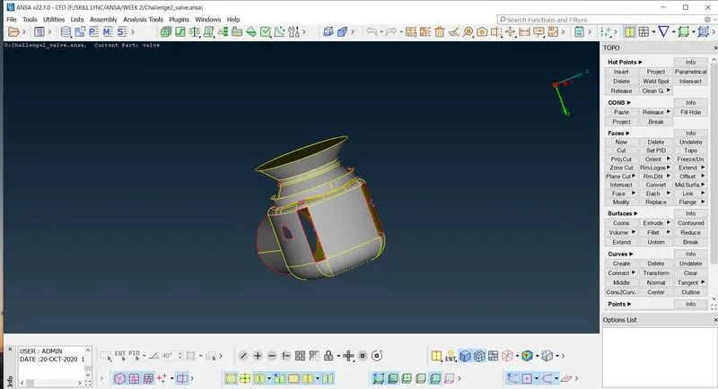
2.Deleting or filling the rough geometry into full structured geometry to mesh.
- Geometry finds with lot of discontinuties and Red colour line projects the presence of Single coons, Blue color line projects the presence of Triple coons, followed by yellow colour which shows the presence of Double coons.
- Single and triple coons are not advisable in meshing. (note: Triple coons are accepted in conditional cases).
- All the discontinued surface are filled by the following step
- TOPO DECK ----> FACES ----> NEW ----> COONS ----> select the surface needs to be filled.
- TOPO DECK ----> CONS ----> FILL HOLE ----> select the surface needs to be filled.
Either (A or B) step is used to fill the single coons of the geometry depending upon feasibility.
First 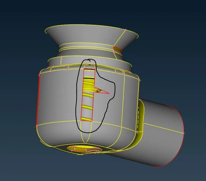 converted into
 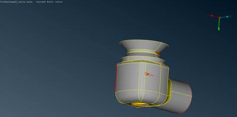 then
then 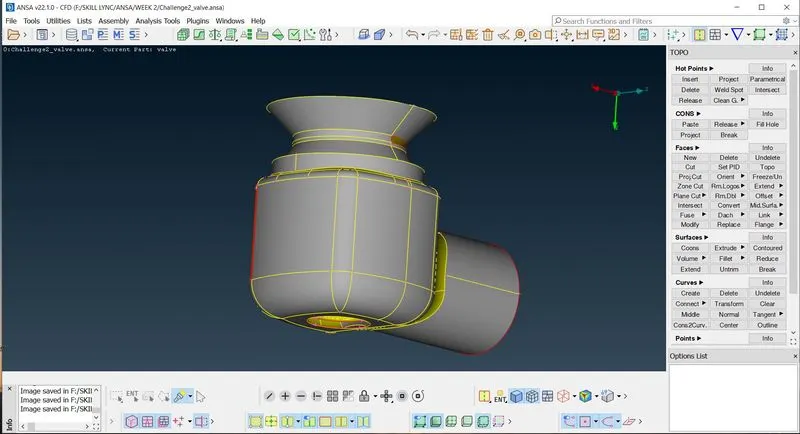
Sceond 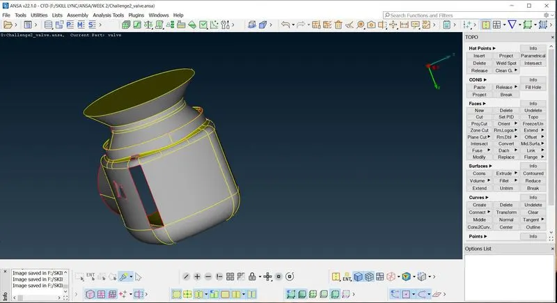 converted into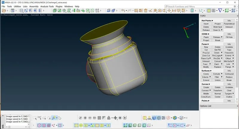
Third 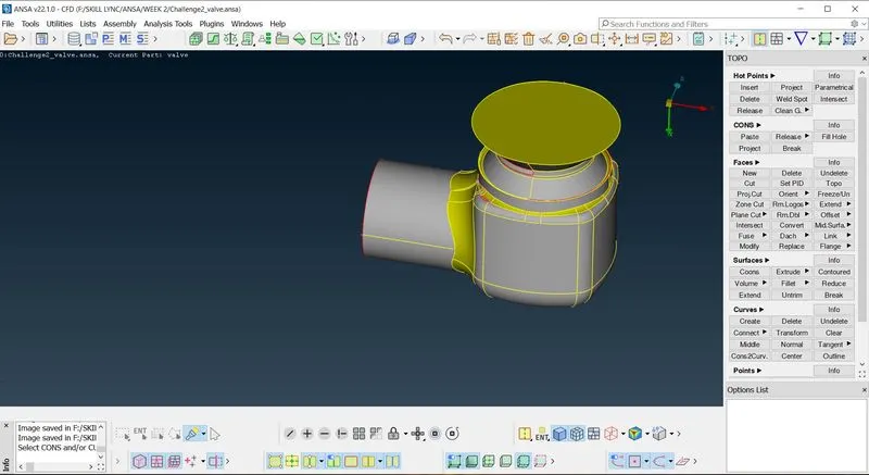 converted into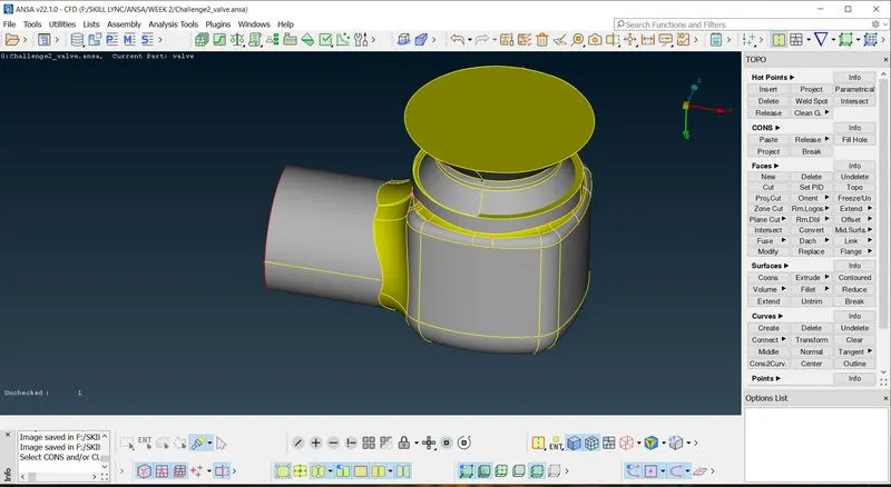
Fourth 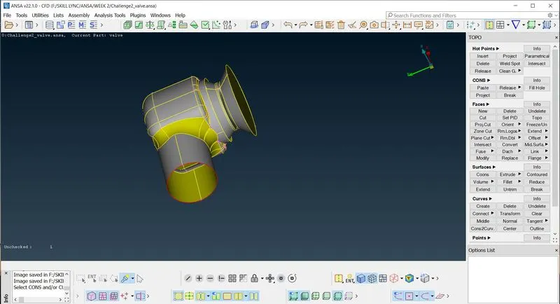 converted into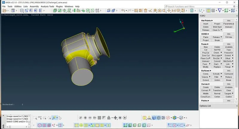
Fifth 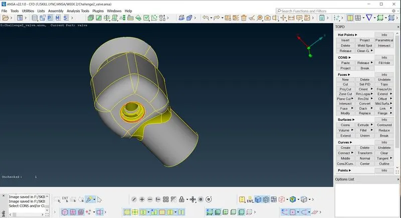 converted into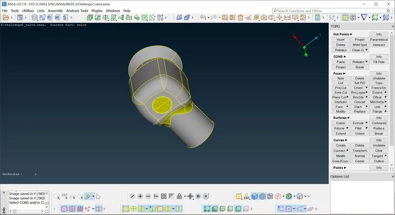
Sixth 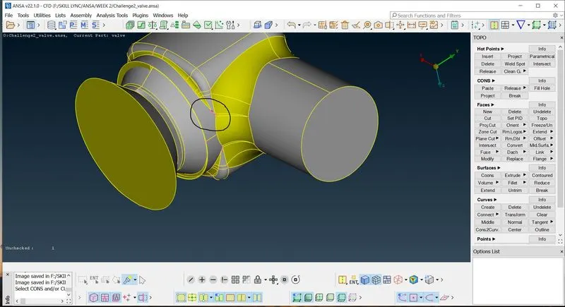 converted into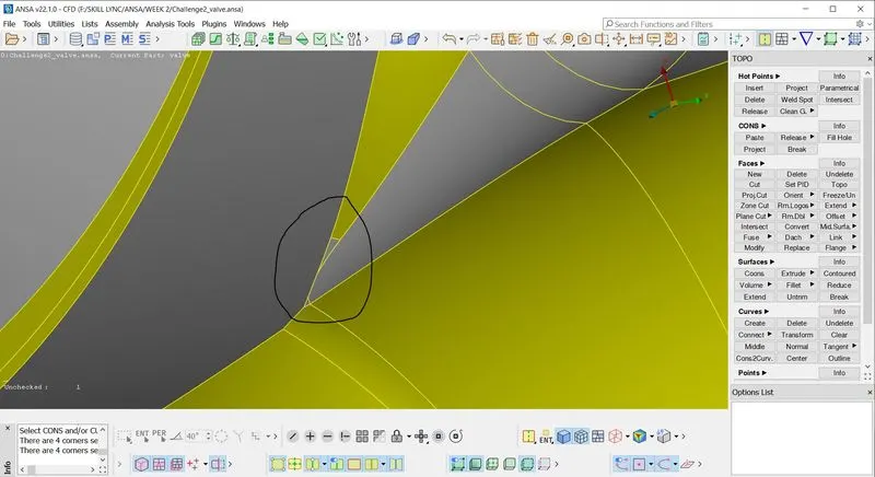
Complete geometry made by filling the surface in the external area and finally
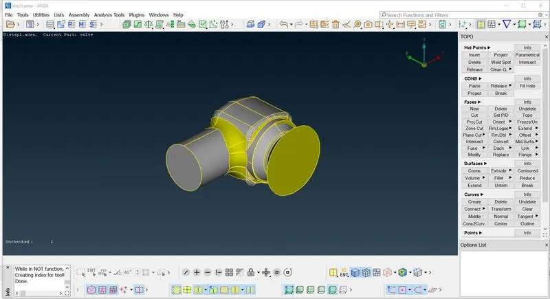
3. Perform Geometry checks and penetration test.
CHECKS MAMANGER ----> GEOMETRY CHECKS ----> EXECUTE
- This will show the errors , and it need to be rectified.
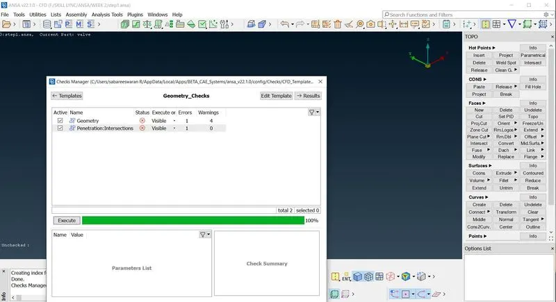
- For geometry checks error split the geometry into different Pid region by pid manager.
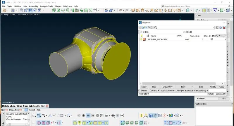
PID MANAGER ----> NEW ----> CREATE THE NAME ----> APPLY TO THE INDIVIDUAL ELEMENT
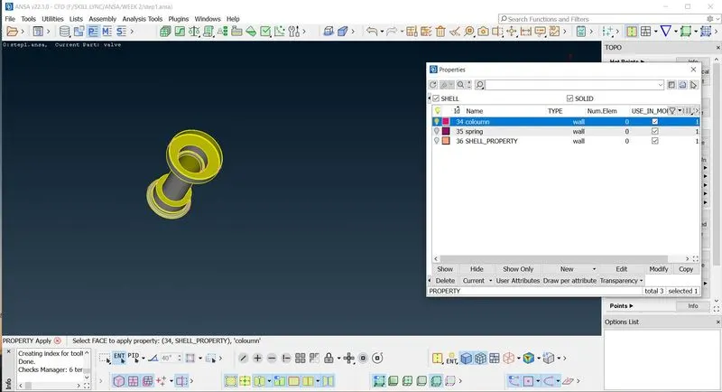
by using "not" option delete the area which is not needed and fix the PID region for the remaining element.
The different elements are:
valve head, spring, coloumn, base, body,inlet and outlet
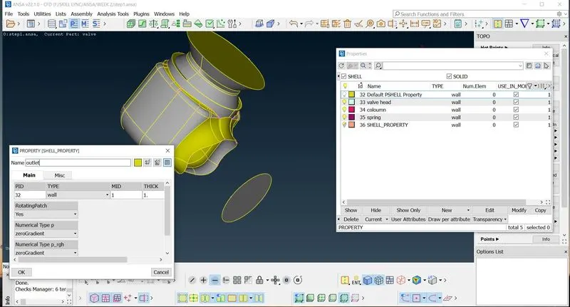
These are the different pid region which is created.
- Geometrical error are single and triple coons that has to deleted and justified.
- penetration issue at the spring and coloumn has to justified.
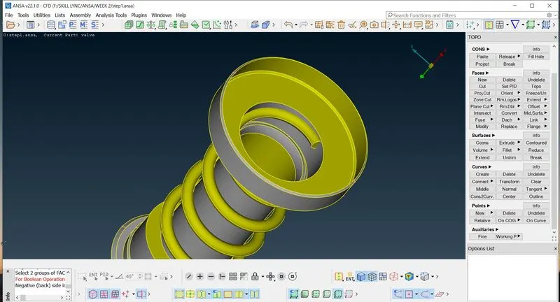
INTERSECT ----> FIRST ----> (SELECT THE SPRING ELEMENT) ----> SECOND ----> COLOUMN (MIDDLE BUTTON TO EXECUTE)
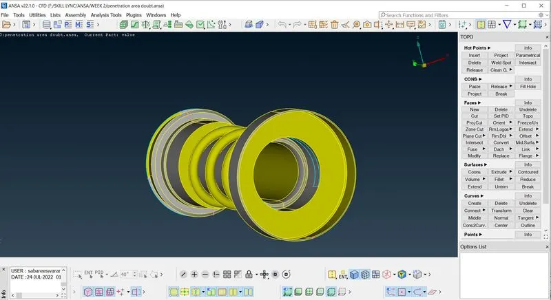
After intersecting the unnecessary surface need to be deleted.
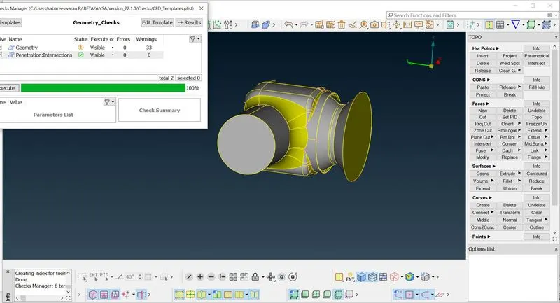
While performing geometry checks ERRORS NEED TO BE ZERO and identify warnings have justified reason.
Once verified move to mesh content.
4.Mesh the geometry for the targeted length.
Element type : tria & Targeted length : 1
MESH DECK ----> LENGTH ----> PERIMETER ----> length (1mm) ----> OK
MESH DECK ----> LENGTH ----> MACROS ----> length (1mm) ----> OK
MESH GENERATION ----> SPOT MESH ----> VISIBLE ----> OK
- Inlet and Outlet mesh
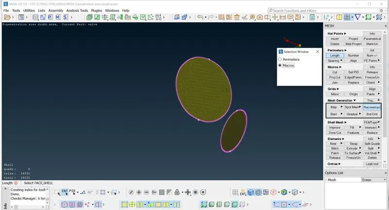
- Base mesh
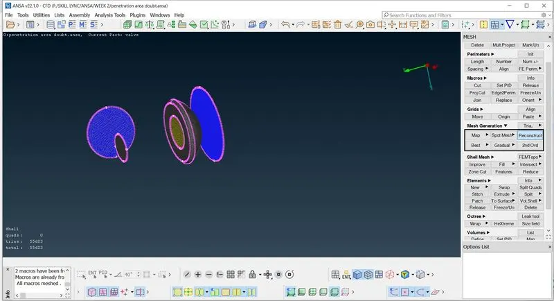
- spring and coloumn mesh
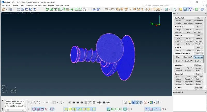
- valve body mesh
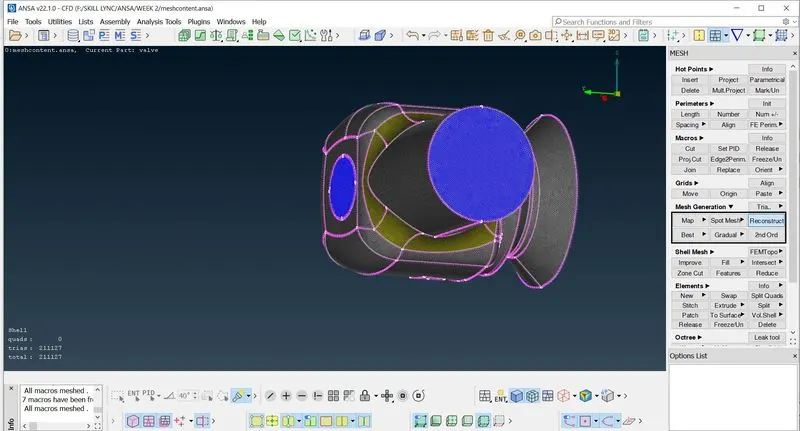
(ALL THE MESH TARGET LENGTH IS MEASURED BY USING THE MESURE OPTION)
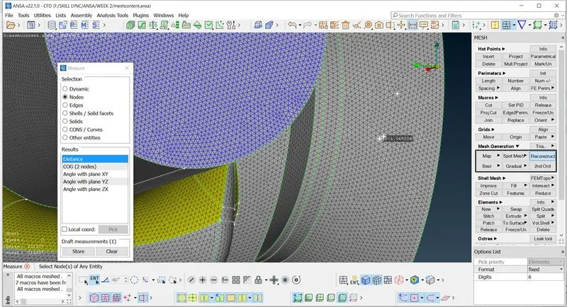
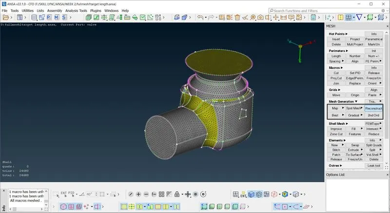
Element type: tria & Targeted length : 3mm
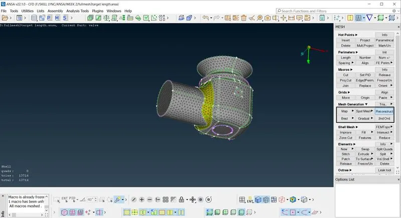
Follow the same procedure and change the targeted length as 3mm&5mm and perform the mesh .
3mm mesh element be like
5mm mesh element be like
Additional keys:
MACROS ----> FREEZE/UNFREEZE (option is used to freeze the mesh view)
LOCK ----> Is used to lock the view on the screen
I NOT ----> option is used to isolate the element from the geometry.
5.Measure the nodal surface dimension using the measure option.
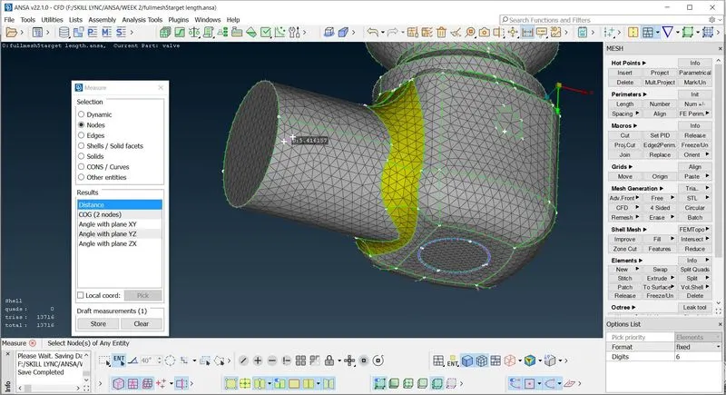
similarly all the node dimension can be measured.
6.Save the geometry accordingly
FILE ----> SAVE
CONCLUSION:
All the three given target length have been meshed in the valve geometry.
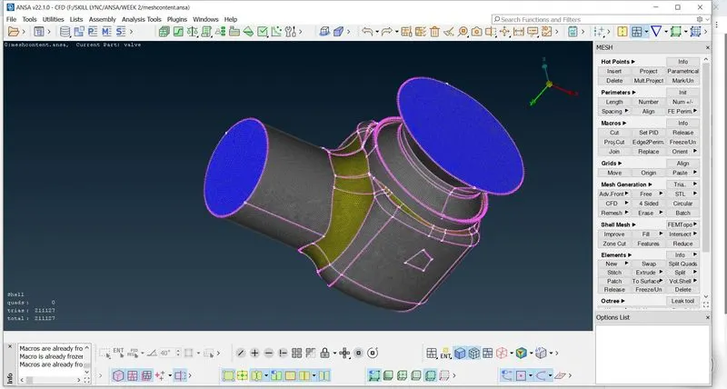
Incase (1mm) --> 1mm target length for the mesh gives a good meshed geometry where the length is small and the geometry founds to be big. mesh length easily fits the geometry.
Incase (3mm) --> 3mm target length for the mesh is slightly detoriated at the sharp sides of the spring and coloumn because the target length is moreover equal to the length of the each coons .
Incase (5mm) --> 5mm target length for the mesh quality is detoriated at the spring area were the large nodal distance covers the smaller area of the spring is the reason to cause such detoriated surface.
Developers fix the target length based onthe purpose and also based on the profile length of the geometry. In this case 1mm target length and element type tria gives a good mesh surface.
Links:
https://drive.google.com/drive/folders/1Ub-DG4iTW_H6ufC8zmqbOWrfh-Y9bZKl?usp=sharing