Week 3 Challenge : CFD meshing on Turbocharger
Aim :
For a given model perform geometrical error and do a volumetric and surface meshing
Procedure:
1. Import the model.
2. Clean up the topological geometry errors.
3. Create different PID'S
4. Perform surface meshing for the targeted length
5. perform volumetric meshing.
6. save the folder.
Explanation
1. Import the model
FILE ----> OPEN ----> import the file.
Turbo charger geometry consist of
1. body casing
2. turbo casing
3. impellar
4. blades stage 1
5. blade stage 2
6. shaft
7. inlet
8. outlet
2. Clean up the topological geometry errors
- ENABLE CROSS HATCH ----> DELETE THE OVERLAPPING SURFACE
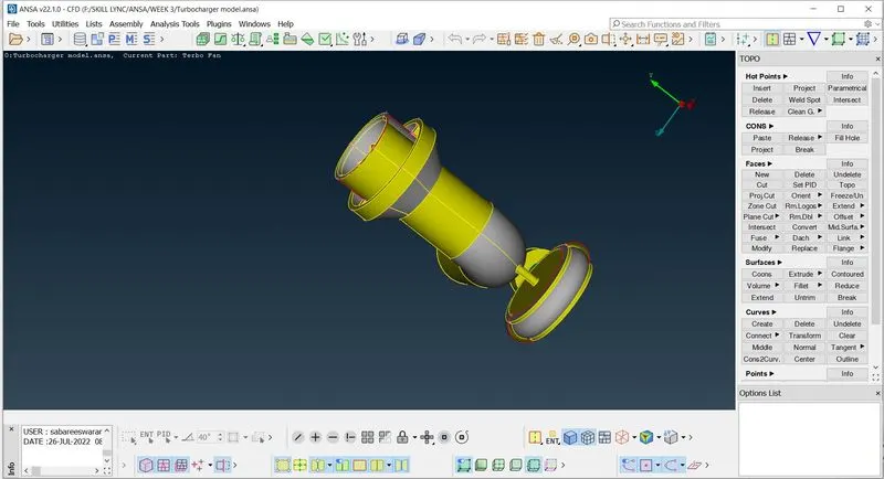
- TOPO DECK ----> HOT POINTS ----> PARAMETRICAL ----> Specify the par length.
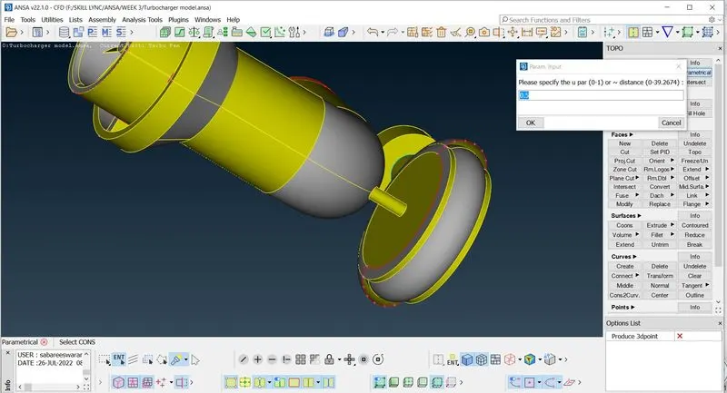
PARAMETRICAL :
This is used to create a hot points on the surface in which the surface is divided equally in a prolonged direction (direction is depend on the selection of surface ) .
using 0.5 as par length create hot points on the mentioned curved surface on both side to fill the surface. More hard points is crreated to make smooth surface as like its symmetry.
- TOPO DECK ----> FACES ----> NEW ----> COONS
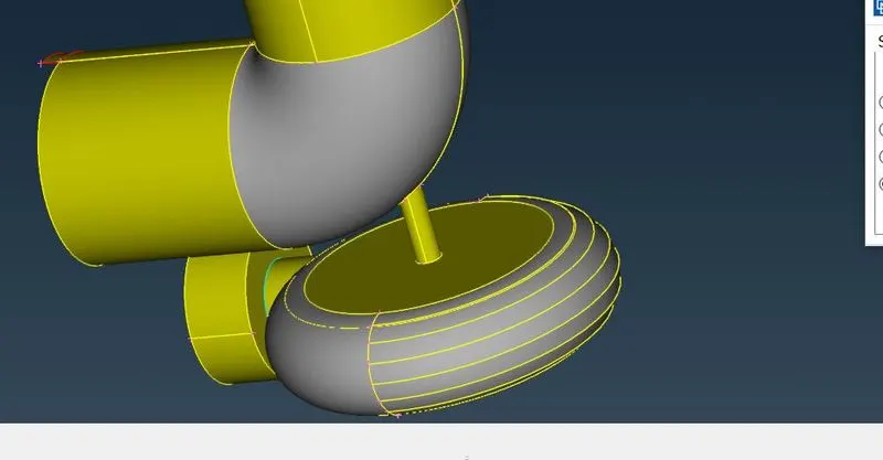
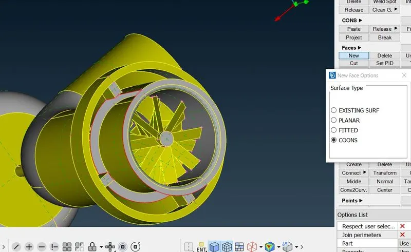
- TOPO DECK ----> HOT POINTS ----> MULTIPLE PROJECTS ----> select the hot points and project on the coon surface
multiple project is used to pick more the one surface / hot points and able to project.
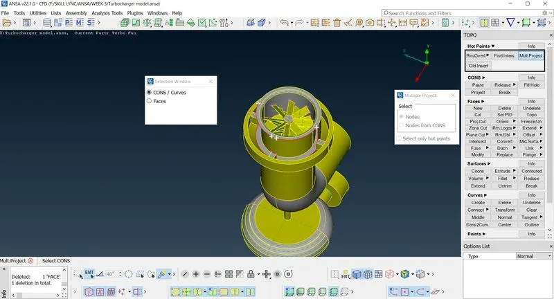
- TOPO DECK ----> FACES ----> NEW ----> COONS
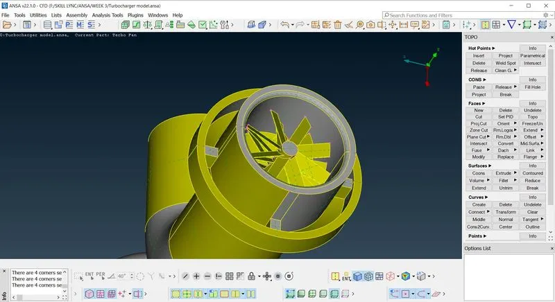
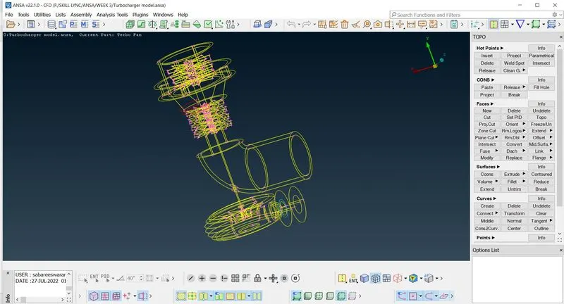
By wireframe mode to view the single and triple coons which will be consider as a geometrical error
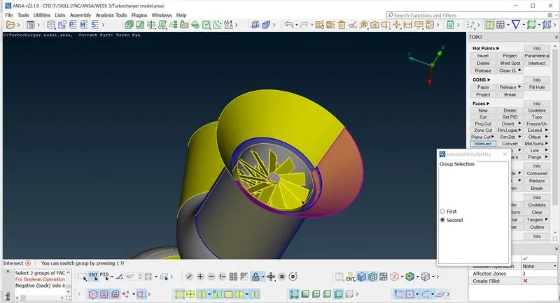
Intersect:
This is used intersect two surfaces which is in contact in order to remove the single coons or triple coons.
- TOPO DECK ----> FACES ----> INTERSECT ----> Select the two geometry ----> OK
- DELETE ----> unnecessary face ----> PERFORM TOPO ----> to get coons to mingle with surface
Project:
- TOPO DECK ----> CONS ----> PROJECT ----> Select the cons and face which is to be projected ----> INTERSECT ----> TOPO
- AUXILLARIES ----> FINE ( used to get refined cons with improved resolution)
Geometry checks :
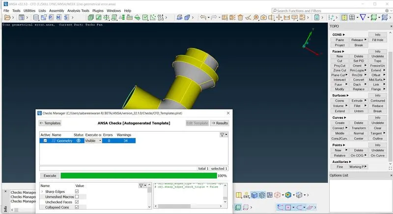
- CHECKS MANAGER ----> GEOMETTRY CHECKS ----> BOTH PENETRATION AND GEOMETRY CHECKS ----> EXECUTE
If the geometry and penetration checks founds with zero error proceed with PID assignment.
Cut and Project :
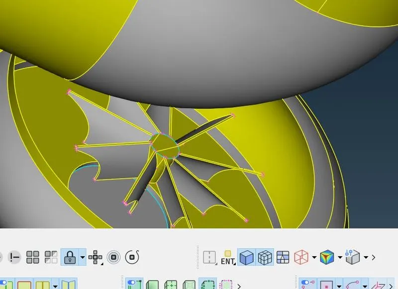
Impellor region is found discontinous
- CUT ----> Select the discontinous ----> CREATE THE COONS ----> DELETE THE OVERLAPPING SURFACE
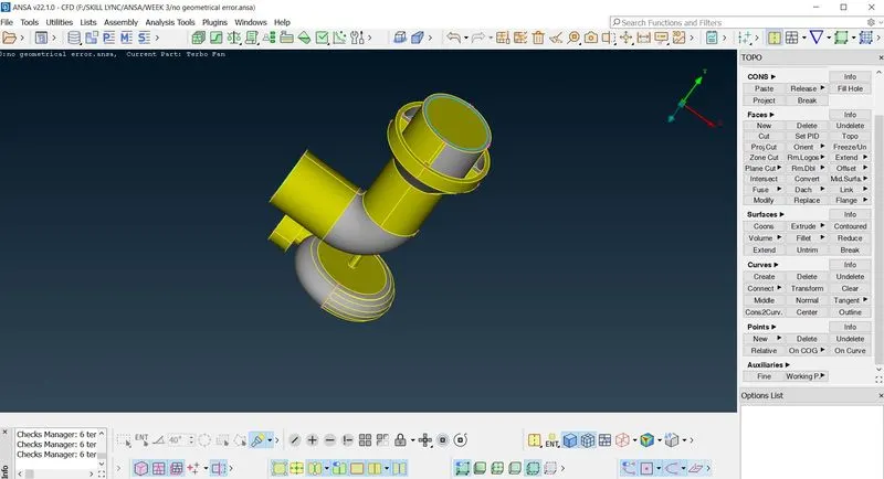
cover the geometry as a closed surface to form a water jet model and to perform surface mesh
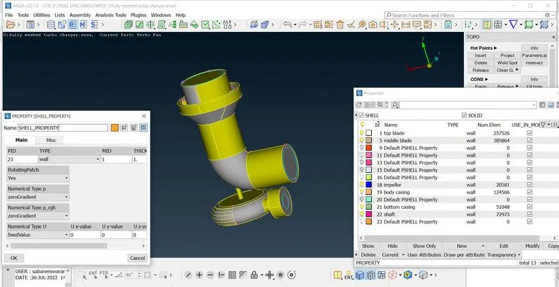
3.create different pid region
- PID MANAGER ----> NEW ----> SHELL PROPERTY ----> Select the geometry to assigned under a single PID by APPLY
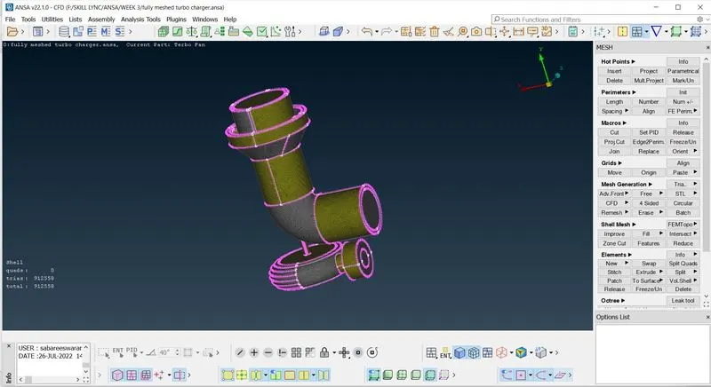
4. Perform surface mesh
- PID MANAGER ----> Select the respective PID such as ( shaft, blade stage 1,2, impellor, body casing, turbo casing, inlet, outlet)
- MESH DECK ----> LENGTH ----> PERIMETERS ----> select the geometry - targeted length (shaft, blade stage - 1mm , impellor -2mm , body casing, turbo casing, inlet, outlet - 5mm)
- MESH DECK ----> LENGTH ----> MACROS ----> select the geometry - targeted length (shaft, blade stage - 1mm , impellor -2mm , body casing, turbo casing, inlet, outlet - 5mm)
- MESH GENERATION ----> SPOT MESH ----> VISIBLE
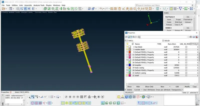
Once all the element meshed the different nodal length is checked by using measure
5. Perform Volumetric mesh
Once Surface meshing completed, next is to perform volumetric meshing.
- VOLUMERIC MESING ----> VOLUMES ----> DEFINE ----> click on whole db
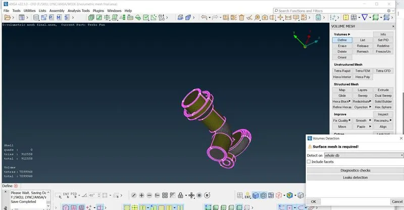
Volumes of the surface meshed geometry is auto detected and create volumes
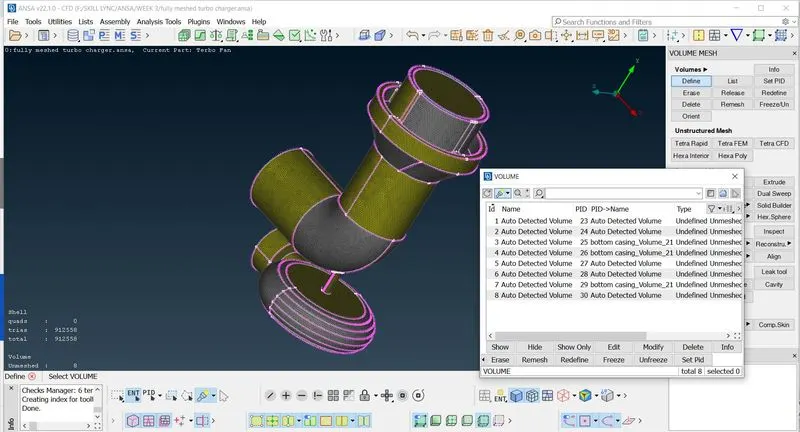
Out of the given volumes, perform volumetric mesh only on the fluid flow region , others are outer surface where you no need to perform volumetric meshing.
once the inner fluid area detected perform volumetric meshing.
- RIGHT CLICK THE DEFINED VOLUME ----> REMESH ----> TETRA CFD ----> OK (Status changed from unmeshed to meshed)
similarly do it for all the volume which is detected.
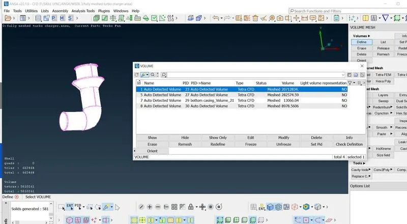
check for unmeshed surface or volumes through a image view(it will show the element type along with no of element and also detect the unmeshed surface)
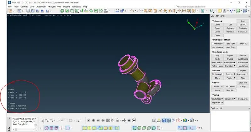
Volumetric meshing is viewed by making a cross section using 'NOT option'
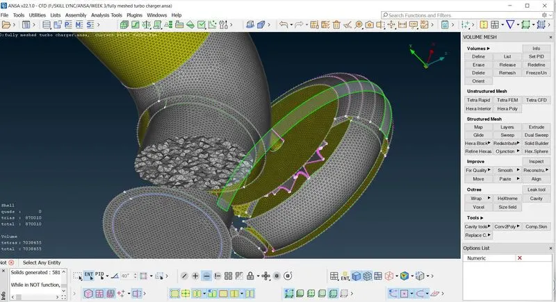
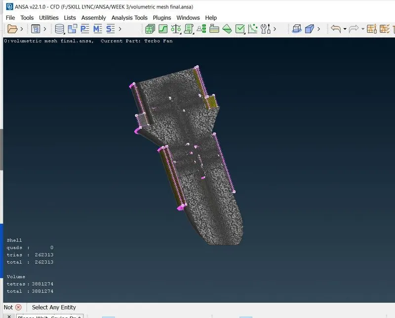
sectional view of the volumetric mesh
6. Save the folder accordingly.
Conclusion:
Surface mesh is done for various target length for different geometry the intersecting area is found to be get manitained for the larger targeted length after some distance the actual target length is achieved approximately.
To perform volumetric mesh, surface mesh to be completed.
Volumetric mesh is for 3d known as solid , surface mesh is 2d known as shell
volumetric mesh takes time to perform compared to surface meshing
Number of element tria is more in volumetric meshing compared to surface meshing (since 3D)
volumetric mesh needs to be done only on fluid flow area , the surface or dimensional area is excluded in volumetric meshing.
SURFACE MESH LINK:
https://drive.google.com/file/d/12_XmNijwG6gimVKZP6JxpeLNoHMWOaPU/view?usp=sharing
VOLUMETRIC MESH LINK:
https://drive.google.com/file/d/1pOWmMiCr4-WfQyAJUAnaQ6zKVn2U8h1A/view?usp=sharing