Week 4 - CHT Analysis on Exhaust port
Aim: To study the Conjugate Heat Transfer Analysis of Exhaust Port using ANSYS Fluent.
OBJECTIVES
The objectives of the simulation are
- Simulation of Conjugate heat transfer on exhaust manifold
- Calculation of wall heat transfer coefficient on internal solid surface
- Maintaining appropriate y+ value for the turbulence model
CONJUGATE HEAT TRANSFER
The contemporary conjugate heat transfer model was developed after computers came into wide use in order to substitute the empirical relation of proportionality of heat flux to temperature difference with heat transfer coefficient which was the only tool in theoretical heat convection since the times of Newton. This model, based on a strictly mathematically stated problem, describes the heat transfer between a body and a fluid flowing over or inside it as a result of the interaction of two objects. The physical processes and solutions of the governing equations are considered separately for each object in two subdomains. Matching conditions for these solutions at the interface provide the distributions of temperature and heat flux along the body–flow interface, eliminating the need for a heat transfer coefficient. Moreover, it may be calculated using these data.
APPLICATIONS OF CHT
Starting from simple examples in the 1960s, the conjugate heat transfer methods have become a more powerful tool for modeling and investigating nature phenomena and engineering systems in different areas ranging from aerospace and nuclear reactors to thermal goods treatment and food processing, from complex procedures in medicine to atmosphere/ocean thermal interaction in meteorology, and from relatively simple units to multistage, nonlinear processes. The applications in specific areas of conjugate heat transfer at periodic boundary conditions and in exchanger ducts.
EXHAUST PORT SIMULATION(BASELINE MESH)
The stages involved in the simulation are as follows
- Geometry
- Mesh
- Setup
- Solution
- Results
Geometry:
The first step is to import the geometry into spaceclaim and extract the fluid volume where the fluid interacts with the exhaust port for 4 cylinder inline engine.
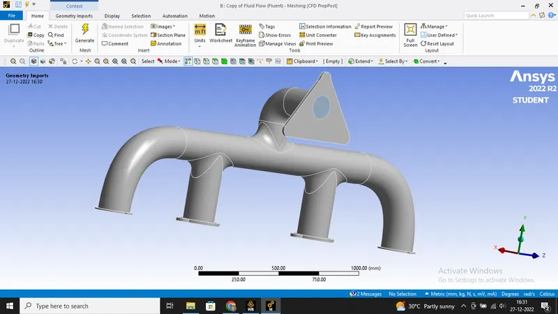
Now we show the image where we have created the fluid volume and now we have to enable the share topology.
Mesh:
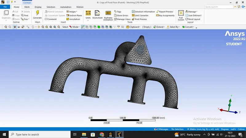
The base line mesh was created to start the simulation with the element size of 150mm and this takes the number of elements count to 137409.
Setup
The setup involves the following changes to the solver.
- Solver - pressure-based solver
- solver state - steady state
- Turbulence Model - K-omega, SST
- boundary conditions
- Inlet velocity = 5 m/s
- Heat transfer coefficient = 20 W/m^2K
- pressure outlet = 0 pascals
Results:
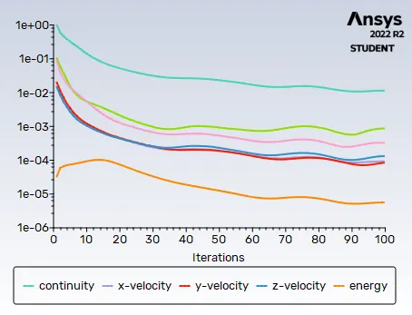
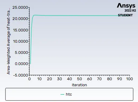
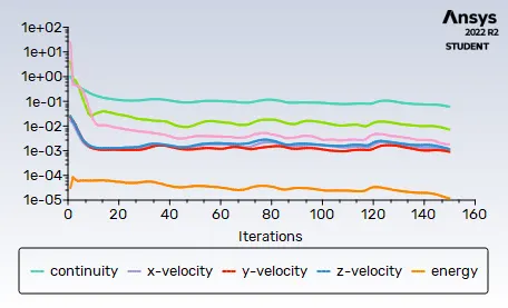
Residual plot:
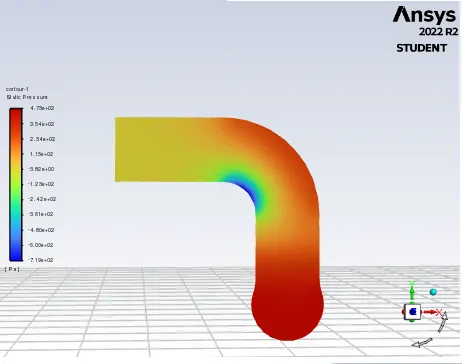
Pressure contour:
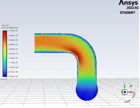
Velocity contour:
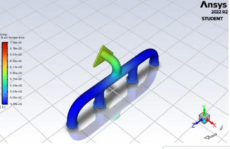
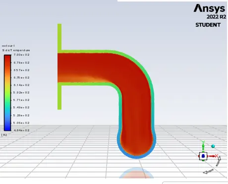
Temperature contour:
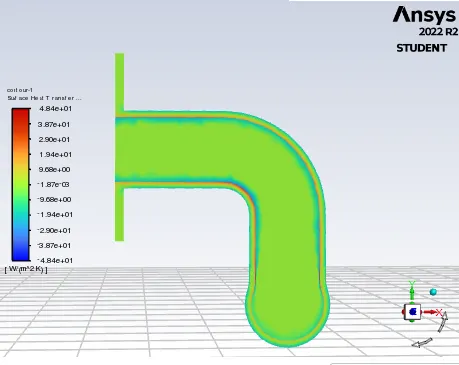
HTC contour:
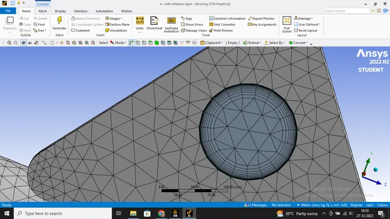
Refined mesh with Inflation layer:
Number of elements = 318646
First layer height= 0.06mm
Number of layers =18
Growth rate =1.3
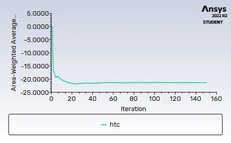
Residual plot:
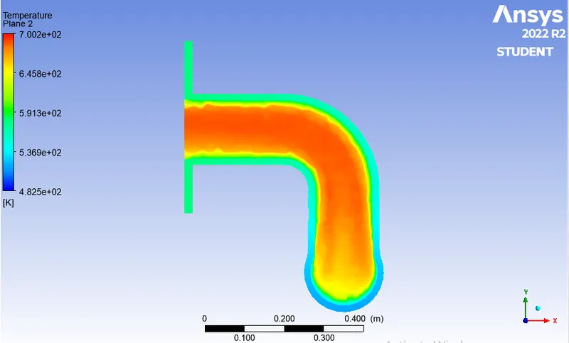
Temperature contour:
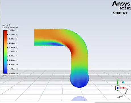
Velocity contour:
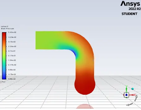
Pressure contour:
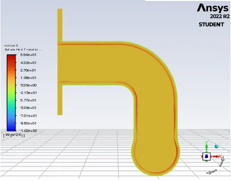
Contour of HTC:
How would you verify if the HTC predictions from the simulations are right? On what factors does the accuracy of the prediction depend on?
Nusselt number is given by:
where:
- D is the inside diameter of the circular duct
- Pr is the Prandtl number
- n=0.4 for the fluid being heated, and n=0.3 for the fluid being cooled.
Nu= Nusselt's Number
Re = Renold's number
We know that the Nusselt's number is a function of Reynold's number, which in turn is a function of flow velocity.
Therefore, HTC is directly proportional to flow velocity.
We can see from the images above that both the HTC and velocity are maximum near the outlet.
Hence, the HTC predictions from the simulations are correct.
Factors affecting Simulations:
- Number of elements in mesh - Finer mesh gives more accurate results. Inflation layers around the boundary - Inflation layers which provide body fitted mesh provide accurate analysis of geometry. It increases the quality of mesh near the boundary interface and helps to capture smooth plots of different quantities.
- Setting share topology - Mesh should be conformal for smooth transferring of mesh in different zones.
- Selection of proper turbulence model according to y+ values.
Conclusion
From the base line mesh which doesn't have inflation layer and from the Refined mesh we can conclude that The model with inflation layer can trap better wall adjacent values and conditions. Thus it signifies the importance of the inflation layer in capturing near-wall phenomenons.
As a fact we know that finer the mesh accurate the values are. The viscous models and solvers should be chosen according to the requirements. A good understanding of solvers and models is needed for CHT analysis.
Y plus values should be maintained depending on the solvers. Comparing the contours of temperature between the baseline mesh and refined mesh, we have observed that temperature is more accurate in case of refined mesh with an inflation layer.