Week 4 - CHT Analysis on Exhaust port
PROJECT REPORT
AIM:
To perform an experiment of conjugate heat transfer and list the importance and application of such problems
CHT – Conjugate Heat Transfer:
Conjugate heat transfer corresponds with the heat transfer in which both heat transfer with solid and heat transfer between fluid both are taking place. Heat transfer between solid is known as conduction and heat transfer between fluids in known as convection, where this both take place is an be called as conjugate heat transfer
Conduction heat transfer happens in solid when faster kinetic energy molecules collide with the molecules with low-speed kinetic energy, and heat transfer takes place
Convection process not happens only convection it takes place along with conduction as the heat transfer along the fluid like air take place with conduction process so, there are many examples of CHT like, Air cooling process, Heat sink, any solid carrying hot fluid etc.
Wherever, the solid and fluid interface takes place this type of CHT can be solved by providing a Heat transfer coefficient which varies by material been used
MODELLING:
Here we are using a inline four-cylinder exhaust manifold, Where CHT is going on with an heat transfer coefficient. Firstly, Fluid volume is extracted and the remaining part is solid with some heat transfer coefficient and there is going to be exchange in heat between the hot exhaust air and the manifold
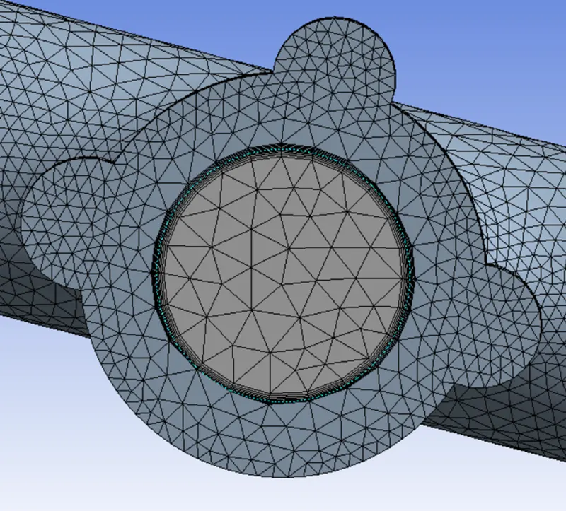
As there is exchange of heat in solid and gases there is shearing between both and so the mesh matches between both volumes
MESH:
Finer mesh with cell count of 399040 is used for simulation
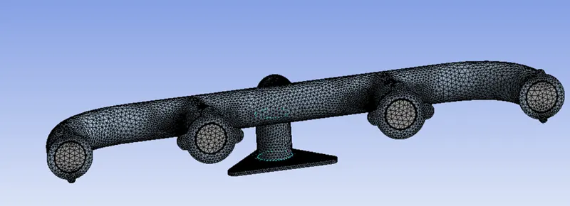
Share tropology is used between both volumes and inflation layers are added to capture proper heat transfer between solid and liquid
SETUP:
Pressure base solver is used with steady state and energy equation enabled. Turbulent model K-epsilon is used for solving
BOUNDARY CONDITION:
Material: Air
Inlet – Velocity inlet – 5 m/s Temperature of 700K
The outer wall – convection, Heat transfer coefficient of 20w/m^2K
Free stream temperature - 300K
Outlet – Pressure Outlet
RESUDAL:
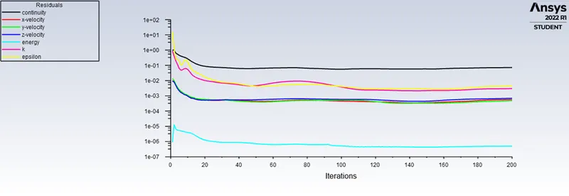
The process slowly converge around 90 to 120 iterations and we can see proper distribution of heat
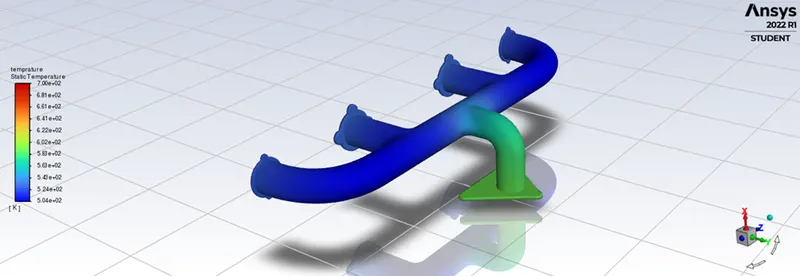
TEMPERATURE CONTOUR:
VELOCITY PLOT
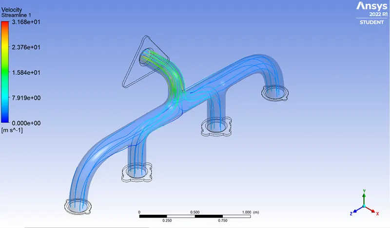
As we can see velocity is lower at the inlet and higher at the outlet, because of the mass conservation the area at the outlet is low than compare to the all four inlets are so the velocity increase to maintain the balance. Also, as the velocity increases, we can see the temperature is also high at the outlet which is shown in below dig.
Velocity Distribution
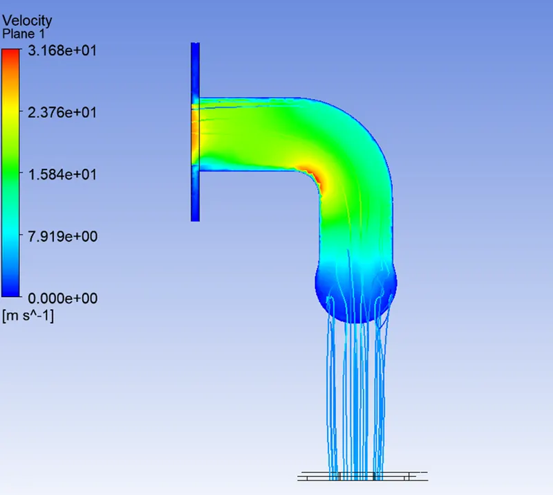
Observe that the velocity is highest at red area, the same are where the wall heat transfer coefficient is highest
HEAT PLANE
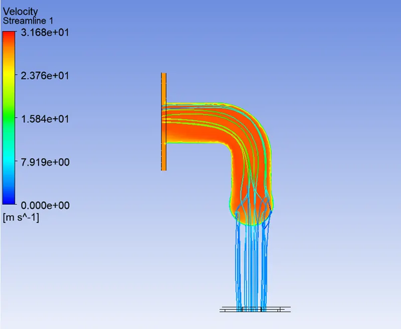
Compare the result with the base line mesh, The refining mesh model gives more accurate results. Adding inflation layers give advantage of accurate velocity calculation at the outlet
Y+ calculation:
Y+ value is dimensionless number which can be define as the value above the plate where the boundary layer is created by fluid, which shows the maximum value of layer creation by which we can check our mesh around the edge where boundary layer will be created. It can be define as a check for the user that the mesh is reliable around the critical area and the velocity is accurate
In our case we are using the K-epsilon model and the wall function we are using is Standard wall function. The lover limit in such case for Y+ value is 11.225
So, substituting the value of Y+ in the formula we can find the minimum layer thickness of first nod of our grid on the edge
After substituting all values, we get value for thickness of first cell as 3mm which is fine in our case as our inflation layers have 5 layers in 5 mm distance i.e., our first layer has the thickness of 1mm so we can say our mesh is within the parameters of value for Y+
HTC VARIFICATION:
HTC – Heat Transfer Coefficient
In CHT conduction and convection occurs, in this process we use natural cooling where Reynolds number depends on Nusselt number
Where, Nu = hl/k
So whenever increase in velocity will result in increase in HTC which will result in increasing in convection
The factors that affect HTC are
PROPERTIES OF FLUID
MOVEMENT OF THE AIR
GEOMETRICAL DOMAIN
CONCLUSION:
In CHT calculation the wall heat coefficient is an important factor, to determine the temperature accurately which depends on the materials involved and velocity of fluid, as the velocity increases the HTC increases and result in increase in temperature