Week 4 Challenge : CFD Meshing for BMW car
Aim: To check and solve all the geometrical errors on and assign appropriate PIDs and also to deploy the surface mesh on the car surface.
Procedure:
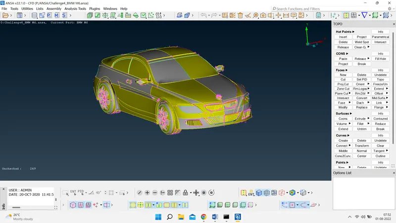
- Import the CAD model.
To import the CAD model we follow the below steps...
Go to file -> open -> browse the location of the CAD model -> select it and click on open.
- Identifying & cleanup of the topological / geometry errors .
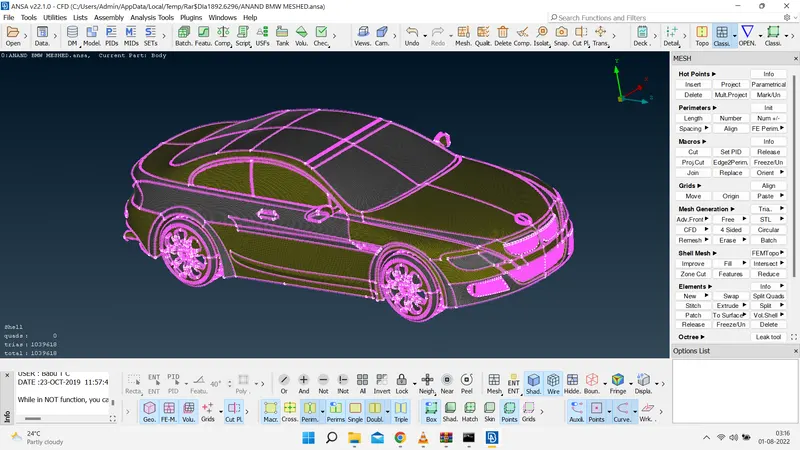
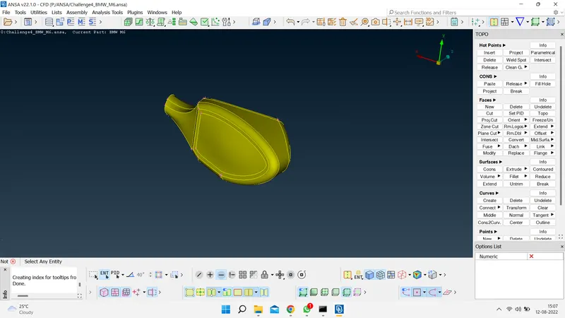
- Before performing any topo clean up , you can observe that the resoution of compenents are not very much good . So to have a better resolution let us first go to mesh deck and decrease the mesh length by selecting the whole model and giving 1mm mesh length .Now you can observe that in the below image the resolution of car is pretty much good .
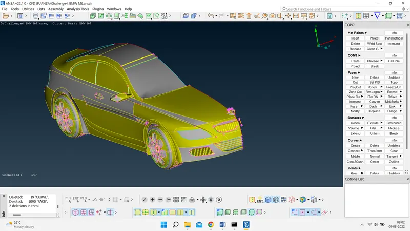
- The given car model has a symmetry on a central axis, the best way of approach is to delete the half of a model and eliminate the topological errors and then meshing on one side & finally perform the symmetry to get the full model again.
- Initially, there were many errors , each of them should be rectified systematically by one after other. The errors are being corrected by selecting the individual features of the car like grills, lights, wheels, logo, windshield , side grill etc., seperately.
- So by following above points , let us select one by one and clear topo errors .
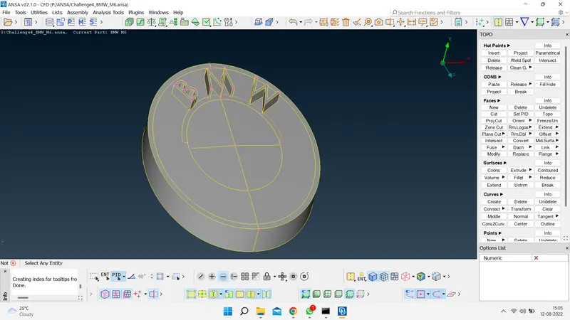
a) Logo
Before Correction:
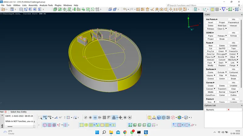
After Correction:
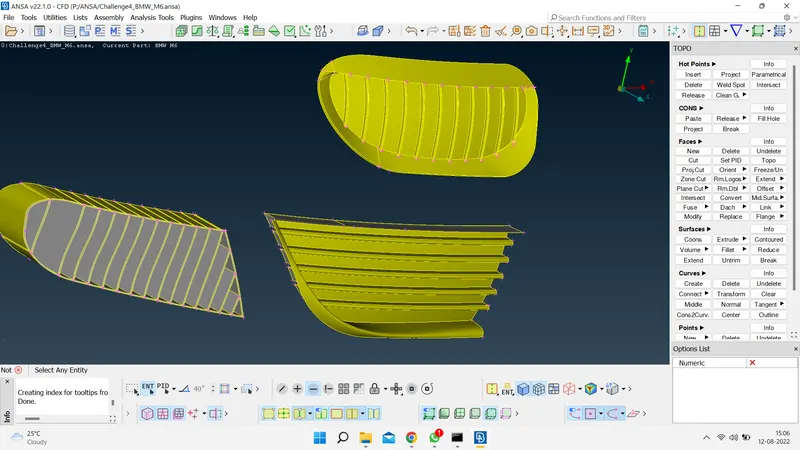
b) Grills:
Before Correction:
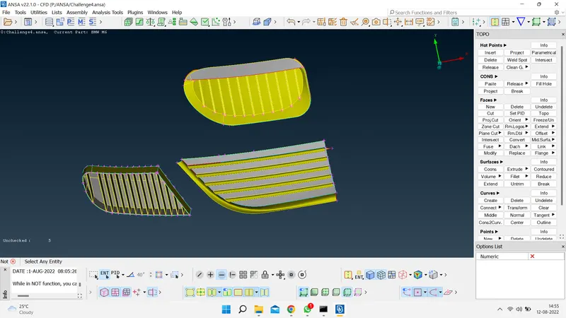
After Correction:
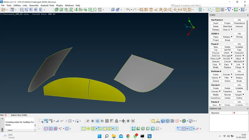
c) Windows
Before Correction:
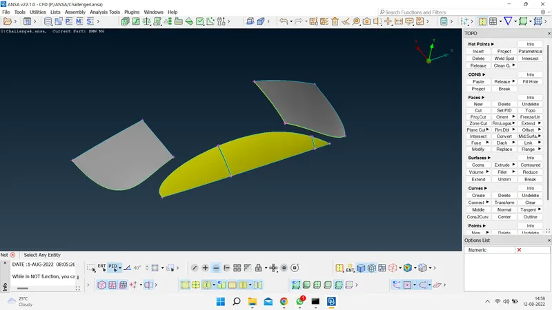
After Correction:
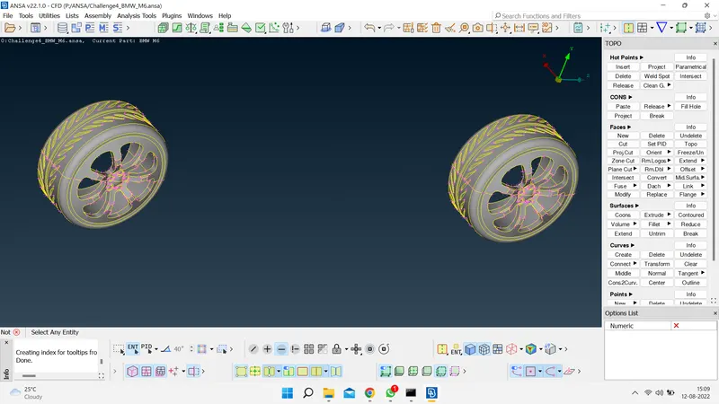
d) Rims and Tyres
Before Correction:
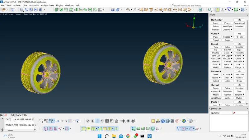
After Correction:
e) Silencer
Before Correction:
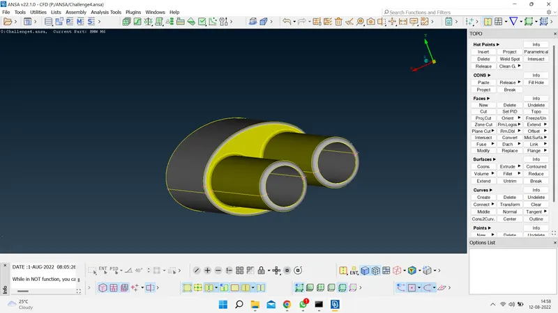
After Correction:
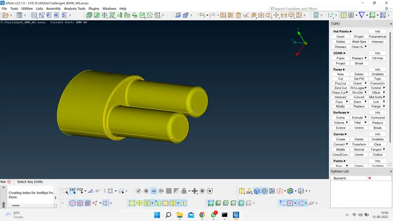
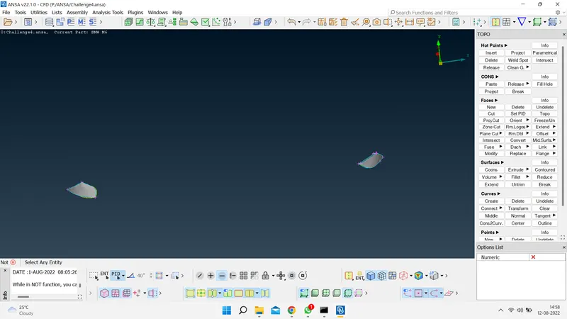
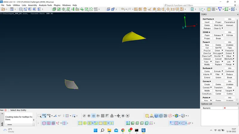
f) Light
Before Correction:
After Correction:
g) Mirror
Before Correction: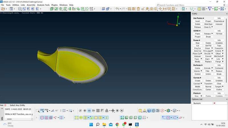
After Correction:
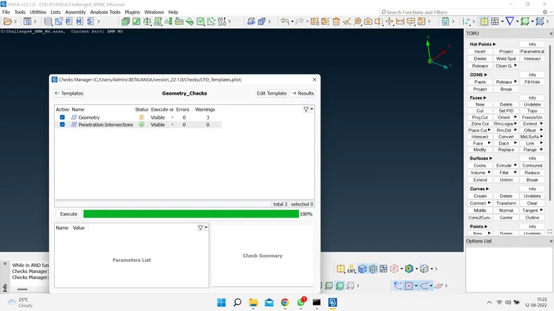
- Geometry and penetration check-up.
- After cleaning-up all the topological errors , the geometry is checked using geometry checks under checks manager.
- Setting-up of relevant PIDs.
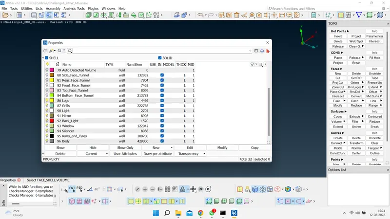
- In this step we assign the PID for different parts and give a name and colour to differentiate between the components and ease up the working on the components individually.This is also done to specify names to different boundary conditions for various parts.We need to activate cross hatches before setting-up PIDs.
- If you open properties manager at the top , you will have some default PID's which are assigned. We have to create new PID's to assign for our components. Inorder to create new PID , right click on properties manager -> click new -> then select pshell -> then again select pshell -> then give name in the popup box -> then ok .You can change the colour by double clicking on the colour box -> then ok .
- In the similar way create PID for all the components.
- Then next thing is assign these PID's to the components of the geometry .
- To apply , we select /click on the PID to apply in the PID manager -> then right click on it -> then click on apply -> then in the geometry select the cross hatch of the surface you want to assign -> then middle click . In the similar way we have to apply PID's we have created . To give the PID we select with the different type of selection available to select the exact surface needed.
- Then after assigning the PID , delete the empty orginal PID's which has no components assigned by using compress .
- In the below image you can see that list of PID's we have assigned.
- Defining the element size or length and setting the mesh parameters & creating the surface mesh and resolving the errors in the surface mesh.
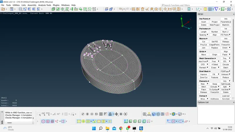
- Here we perform all the three tasks ,defining the element size or length and setting the mesh parameters, selection of meshing type and generating surface mesh of the CAD model and resolving the errors in the surface mesh by selecting each PID one by one and perform above tasks .
- Before meshing we have to give quality criteria .Here we select openFoam solver deck,so that we get the quality criteria.
- Here as we have different surfaces , we will use different quality criteria for different surfaces , we will change mesh length as per our surface complexity and surface size . If surface is small we have to use smallest target length , if larger we use accordingly.
- But before doing these tasks , we will follow following steps so that we don't have any off elements later in meshing stage . We will try to remove small surfaces that are smaller than our min mesh length , we will directly remove the cut ,which are unnecessary if found small. If that cut or feature line is necessary , if we remove that cut it may loose shape , in that type of scenario me make a cut at another location and remove the orginal cut causing problem , so that there is not much change in geometry .The new cut should also satisfy the minimum length criteria . If not able do cut or that feature line is very important to maintain shape of geometry ,then we will reduce the min length value so that ,our element length would not fail.By following these steps we will evaluate all the PID's / components .
- By following these processes we completed evaluating our model and next thing is to do meshing.
a) Logo
b) Windows
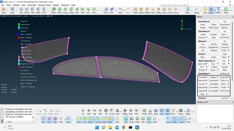
c) Mirror
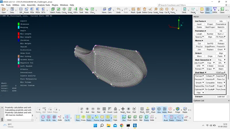
d) Silencer
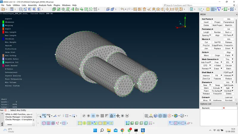
e) Lights
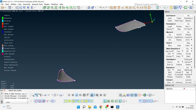
f) Rims and Tyres
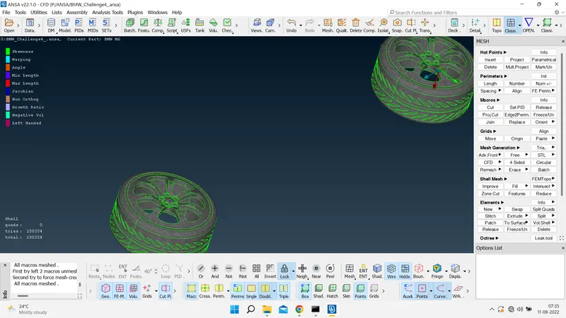
g) Grills
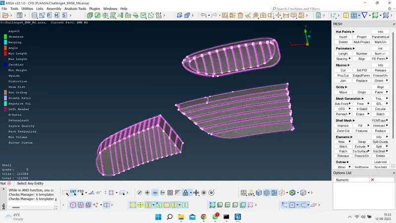
h) Body
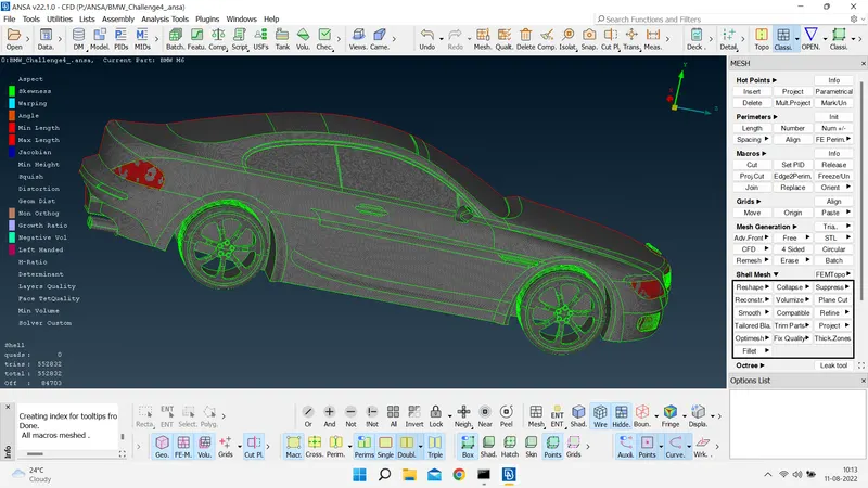
- Creating the Full Model Using Symmetry Option.
- Here we Perform the symmetry to get other half of the model .
- The Second Half part of the model which is symmetric about the centre line is created by using the Function 'Transform'.
- Transform:- This function is used to Translate, Rotate, scale, mirror & Relocate an Entity.The selected Entity can be moved to a new position or copied the same at a new location.
- Transform feature can be selected from the utility browser and it asks for what to be performed in the same function such as move, copy and link. In copy & move 5 features can be observed.
- As we are performing mirror, go to symmetry after selecting copy and use 3 point to create a symmetry about a centre line.
- The 3 points should lie on the line about which the symmetry is required & for accurate result the three points should be at different locations three dimensionally.
- Transformation Option: Asks whether to Create a Seperate PID or Retain in the same PID, also whether the offset is required for the new parts.We keep it to default as not offset or change of PID is needed.
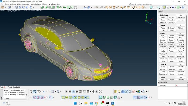
- Creating the wind tunnel for external flow CFD analysis and surface mesh of wind tunnel.
- To perform external flow CFD analysis a wind tunnel has to be created around the car. It is created in TOPO mode as a Rectangular box. The Dimensions of the wind tunnel is also important so as to capture the exact flow around car. The dimensions are as follows:
- Inorder to create a Wind tunnel, first create a point by selecting relative at 80mm from centre by selecting a hot point at a distance of 80 mm to bottom .
- By taking that point as reference , we create anotheer point to front of car at a distance of 654 + 4* 1300 = 5854 mm (654 mm is distance from centre to front of car and 1300 mm is length of car ).
- Then we create another point at the back at a distance of 610 + 6* 1300 = 8410 mm (610 mm is distance from centre to back of car and 1300 mm is length of car ).
- Then we create another two points on both sides of car , with the help of front and back of car , which we have created , such that we can join all the four points with the help of curve and create a surface there with the help of 4 curves .This completes creation of bottom part .
- Then we create top face by using offset at a distance of 375 + 3* 1300 = 4275 mm (375 mm is distance from centre to top of car and 1300 mm is length of car ).
- Now using these two surfaces we create new surfaces on all sides and close the volume , such that it forms a wind tunnel .
- Now we create and assign PID's for the wind tunnel walls.In the below image we can see that PID's are created and assigned.
- The below image is the wind tunnel we have created.
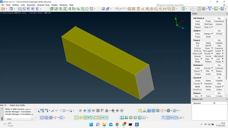
- Next thing is to do surface mesh to the wind tunnel .
- Now that the wind tunnel has been modelled, it has to be surface meshed first, such that the mesh size gradually grows from top to bottom.
- If we have refined mesh ength at the top ,then we will have lot of cells and lot of computational effort is required to solve .So , we give varying mesh length .
- This can be done by using the spacing option under perimeters in mesh utility menu.
- choose geometry biasing option & set the dmin value as 20 and dimit value as 100 and facot as 1.1 and select all the four vertical perimeters.But before that we surface the top part by giving a length of 100 mm and bottom part with a length of 20 mm .
- Then generate surface mesh. In the below image we can see that the mesh length is varying and increasing from bottom to top .
- In the below image we can see that the surface mesh is completed successfully for whole model and wind tunnel and mesh length is varying,increasing from bottom to top .And also there are lop of elements .
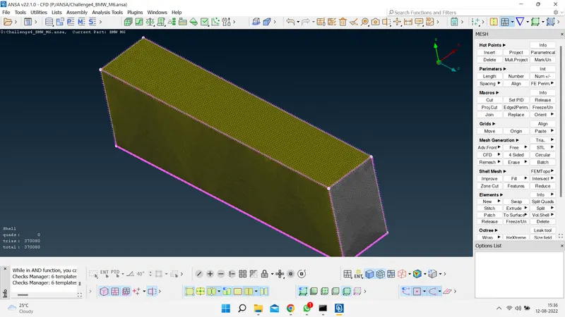
- Generating Volumetric Mesh
- Now as surface mesh is completed ,next thing is to do volumetric mesh . To do volumetric mesh we have to define volumes . Then ANSA auto detects volumes , in that we keep only the volume between car surface and wind tunnel , and as tyres and silencer are not attached , then each of them forms one volume means 4 tyres and two silencers 2 volumes which ae the volumes we delete .We keep the first volume as we are doing external flow analysis .
- In the below image we can see the required volume between car surface and wind tunnel .
- In the below image we can see the volumes which are not required and needs to be deleted .
- Now as there is only one volume left ,for volumetric mesh to be done we use tetra CFD under unstructured mesh .But as the volume created by wind tunnel is very large and as it is of lot of meters and our mesh length is in still mm , it will create lot of elements ,So it will take lot of time to finish volumetric mesh .So we can guess the volume created will be hallow inside of car and other parts where the volumes we deleted and whole other location will be filed with cells .So we cwill stop here with surface mesh as volumetric mesh further takes a lot of computational effort .
- In the below image we can see the final mesh before performing volumetric mesh .
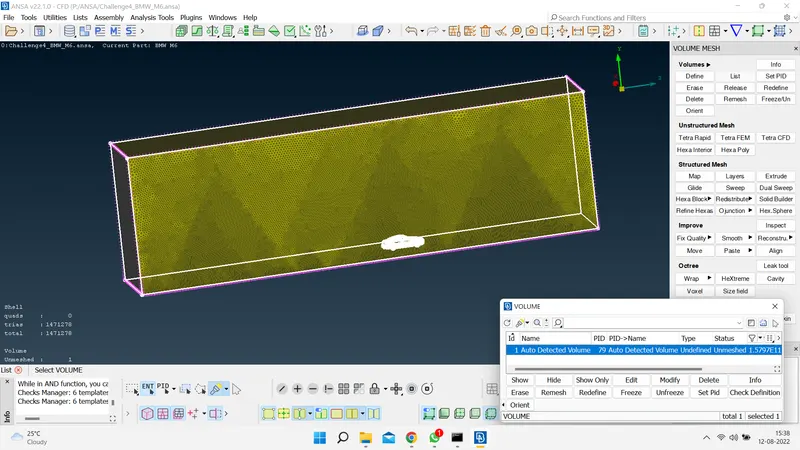
CONCLUSIONS:
The BMW M6 Model is cleaned thoroughly and the wind tunnel is set up. The surface mesh is also generated and the quality of the mesh is improved.