Week 3 Challenge : CFD meshing on Turbocharger
Aim: To eliminate the topological errors that are acquired in the given Turbo Charger CAD model and perform surface and volumetric meshes with different mesh lengths for different components and do the required actions for those meshes.
Procedure:
1) Eliminating Topological Errors
Clear the errors which are acquired during the design. There was some glitching on the surface of the model i.e presence of unwanted components in the inner parts of the model, which is due to imperfect design. These errors are identified by single cons or Tripple cons on the surfaces. Do geometry check to visualize the Single cons (not acceptable and remove them) and Tripple cons (if possible try to remove them) and also do the Penetration check.
Here is the error-free model: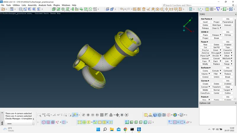
2) Assigning PIDs
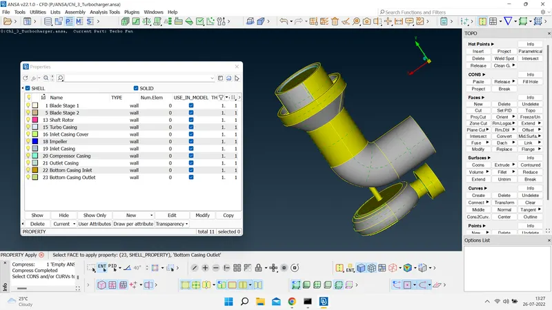
Then the next phase is to assign the Property IDs (PIDs). This is used to differentiate each component with different names and colors and to perform different meshes too. The bulb in the selected PID is glow based on whether the selected PID is visible or not. For the invisible inner components, the bulb will not glow.
we just the assign the pids to the model in the properties tab to
- blade stage 1
- blade stage 2
- shaft rotor
- turbo casing
- inlet compressor casing
- outlet compressor casing
- inlet casing cover
- compressor casing
- impeller
- turbo casing inlet
- turbo casing outlet
3) Compress the model
Before meshing we need to compress the model to delete the unwanted faces, nodes point empty parts, and pids. The compress option is used to view only the visible components in the model. This option generally simplifies the model by not showing the invisible components. The most important to know about the compressor option is, that once compression is done, we cannot retrieve those components in the model.
4) Meshing: 2D Mesh
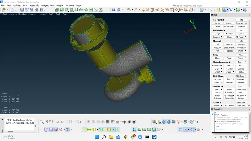
we meshed the model by using the free mesh tool using the element shape as tria.
The mesh length for different pids are
- blade stage 1:1mm
- blade stage 2:1mm
- shaft rotor:1mm
- impeller: 2mm
- compressor casing:5mm
- turbine casing:5mm
- internal compressor casing:5mm.
After meshing due to the difference in the mesh lengths at the intersection of the shaft rotor with impeller and compressor casing and turbo casing at that intersection points the mesh is not accurate so we have to re-mesh on those unmeshed surfaces. After this, it can be seen that in the meshing operation of the compressor casing which has a mesh length of 5 mm, and the shaft rotor which has a mesh length of 1 mm, there was a sudden decrease in the interface of the casing and the shaft. It is not considered an error in meshing, but in terms of visualizing, we should consider that.
5) Meshing: Volumetric Meshing (3D Mesh)
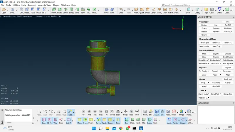
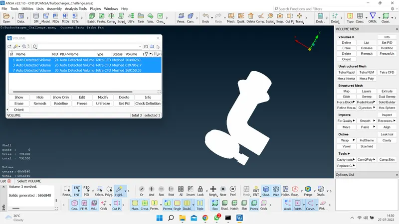
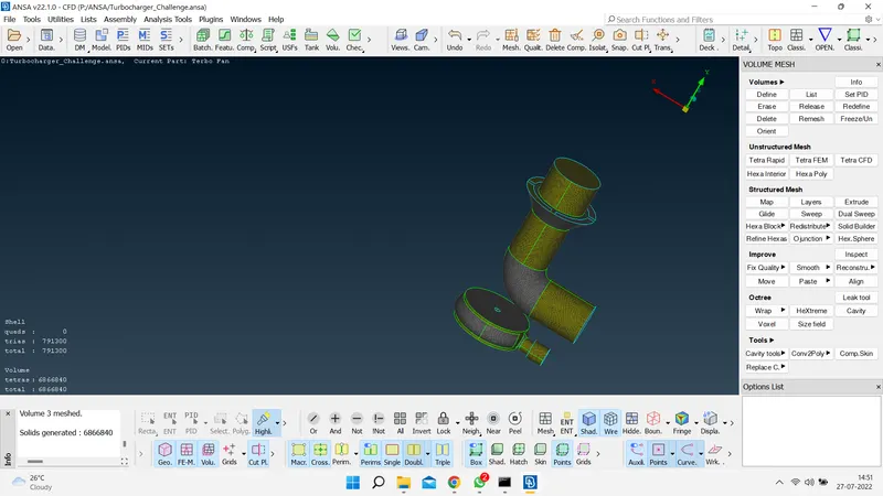
After completion of the surface meshes to create the volumetric mesh first we created the volumes at the openings assigning pids to them and we meshed them. the volumes that are created now the model is ready for 3d meshing. Now we get into v. mesh option and we perform the volume detecting option hence 8 volumes are created as shown below. we now delete the unwanted volumes or volumes that were not present. After deleting the unwanted volumes we have the volumes shown below. Now it is time to perform the 3rd mesh or volumetric mesh by using the unstructured mesh using tetra CFD mesh.
Learning Outcomes:
From this project, I have learned how to perform surface meshing and volumetric meshing and get exposed to different tools in the ansa
Meshed Turbocharger Link:
https://drive.google.com/file/d/1L5fjN4IBtkjXVUCuQoQBGSarJSwoSPkM/view?usp=sharing