Week 4 Challenge : CFD Meshing for BMW car
Aim:
- To clean the geometry.
- Mesh the components part by part.
- Eliminate off elements present in the mesh.
Take away:
At the end of this article one will be able to,
- Use different tools to clean the geometry.
- Understand the quality criteria assigned to each and every PID.
- How to tackle the off elements if present in the mesh.
==============================================================================
NOTE: THIS PROJECT CONTAINS LOT OF ERRORS. REPETATION OF THE SAME TOOL WILL NOT BE DEMONSTRATED.
==============================================================================
PRE CLEAN UP GEOMETRY:
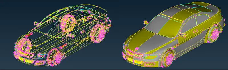
- There are lot of red and blue cons.
- Red cons are edges with one surface attached and blue cons are edges where three surfaces meet.
- So the goal here is to remove red cons and avoid the formation of blue cons.
- This will be done part by part for easy access.
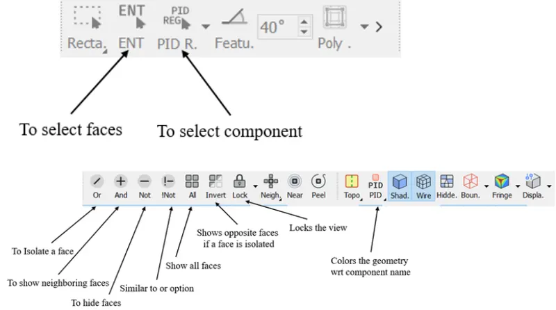
Essential Tools:
==============================================================================
--> Resolution:
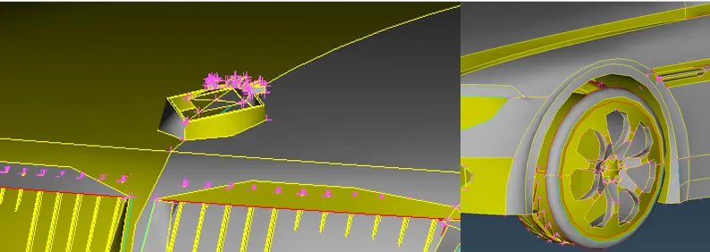
- As observed the geometry has a very poor resolution.
- This can affect the physics while running the simulation.
- This can be done by navigating to LENGTH option in MESH DECK (MESH DECK >> PERIMETERS >> LENGTH).
- Assign a value of 1mm.
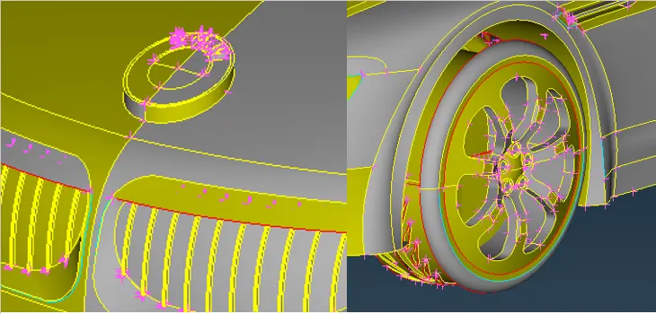
- Resolution is much better than before.
- Now we can resolve the errors part by part.
==============================================================================
>> Exploring the UNIVERSAL DELETE option:
- Since the model is symmetrical, we will be deleting one half of the car geometry, clean the remaining half and the apply symmetry optoin after completeing the clean up.
- UNIVERSAL DELETE option is present in the top ribbon.

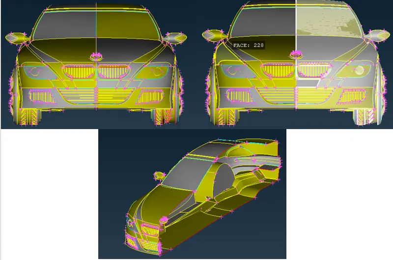
- Now we will workout on the remaining half of the geometry.
>> Exploring the PASTE option:
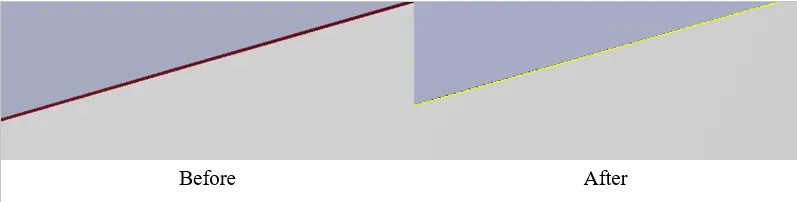
- This is used to paste one con onto other con.
- Select PASTE option. (TOPO DECK >> CONS >> PASTE).
==============================================================================
Bottom grill clean up:
- There are lot of unnecessary surfaces.
- Objective here is to keep a common volume inside the car so we will be deleting/modifying few surfaces.
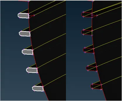
- The above selected surfaces are not required. So we can go ahead and delete the surface.
- We have to create a comman volume.
>> Exploring the PROJECT option:
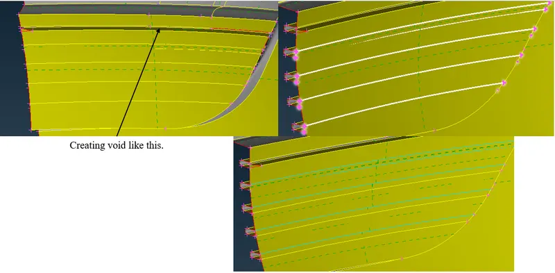
- This will project the cons on the surface.
- Select PROJECT option. (TOPO DECK >> CONS >> PROJECT).
>> Exploring the NEW option:
- This tool is used to create new surface/face.
- Select NEW option. (TOPO DECK >> FACES >> NEW).
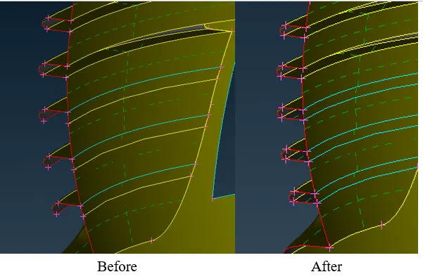
>> Exploring the EXTEND option:
- This tool will extend the cons on a particular surface of interest.
- It only works for red cons.
- Select EXTEND option. (TOPO DECK >> FACES >> EXTEND).
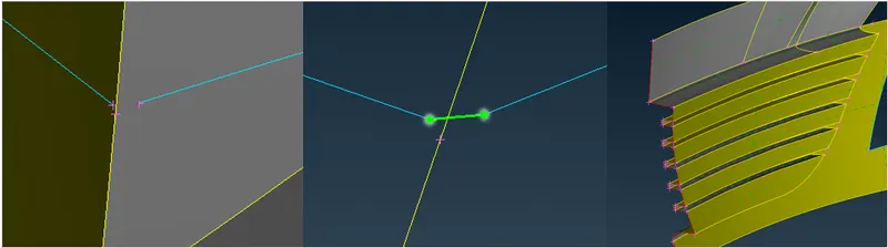
- The final objective is shown below:
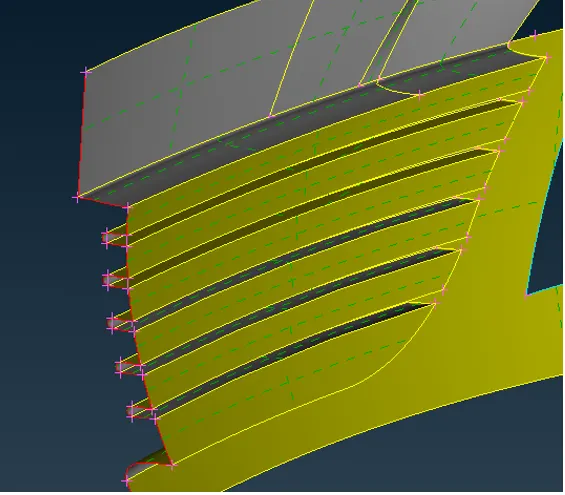
- The red cons will go away once we do symmetry.
==============================================================================
Side grill clean up:
- Objective is to create a common volume.
- Eliminate the red cons and avoid blue cons.
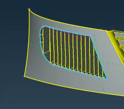
- We will be removing the triple cons first.
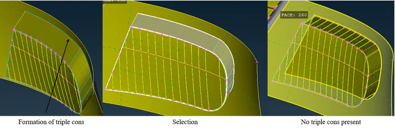
- It is quite evident that there is no triple cons present there after using the UNIVERSAL DELETE option.
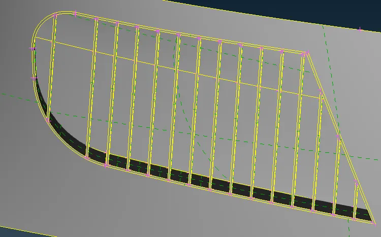
- The ribs in the above figure will form its own local volume.
- Inorder to avoid local volume formation, we must open the ribs from the rear end.
- Delete the surfaces as shown in the figure below:
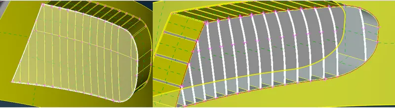
- Now its time to make some modification to the existing surface.
- This is done using the CUT option. (TOPO DECK >> FACES >> CUT).
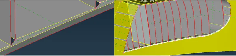
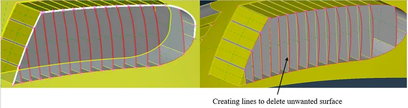
- Similarly, we will be modifying the upper surface.
- We will be creating lines to delete unwanted surfaces.
- This can be done using CUT option to create the lines. (TOPO DECK >> FACES >> CUT).
- And lateron surfaces can be deleted using UNIVERSAL DELETE option.
>> Exploring the FILL HOLE option:
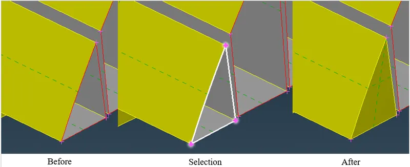
- This tool is used to fill an empty surface.
- Select FILL HOLE option. (TOPO >> FACES >> FILL HOLE ).
>> Exploring the PARAMETRICAL option:
- This tool allows us to create a hot point at some distance from any local reference location.
- Select PARAMETRICAL option. (TOPO DECK >> HOT POINTS >> PARAMETRICAL).
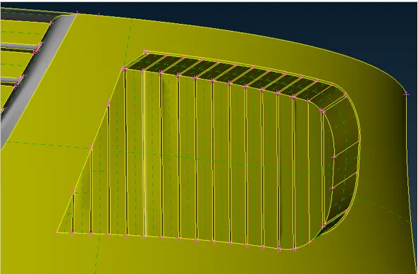
- The final output should be as shown in the figure below:
==============================================================================
Logo clean up:
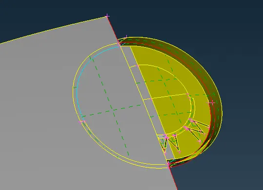
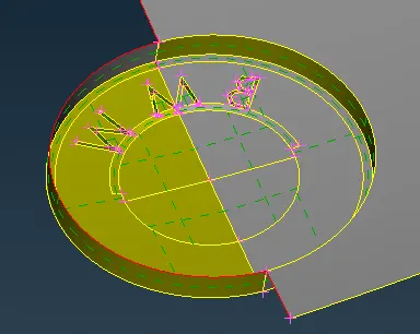
- Major clean up is required at the bottom of the logo.
- We must clean the the unwanted surfaces using UNIVERSAL DELETE option.
- Final output must be like the figure shown below:
- We can go ahead and delete the internal surfaces newa the windshield and rear of the car.
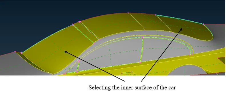
- Resolved output can be seen below:
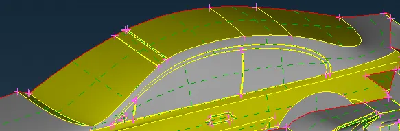
- There are no single and triple cons present near the windsheild, rear and the windows.
==============================================================================
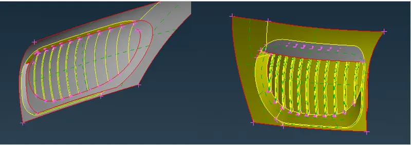
Upper grill clean up:
- Obejctive here is to keep common volume inside the car.
- Make sure that we do not form local volume.
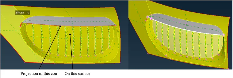
>> Exploring the PROJECT option:
- This tool allows us to project cons on seleted surface/face.
- Select PROJECT option. (TOPO DECK >> CONS >> PROJECT).
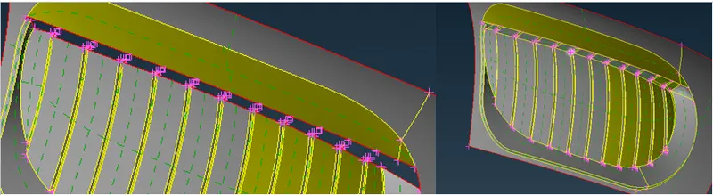
- We will be projecting cons on to surface as shown in the figure below:
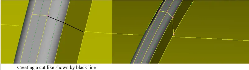
>> Exploring the PROJECT CUT option:
- This tool allows you to create a cut perpendicular to the choosen surface and hot point of a con.
- Select PROJECT CUT option. (TOPO DECK >> FACES >> PROJ.CUT).
- Next step is to delete the top surfaces using UNIVERSAL DELETE option as shown below:

- We will be cleaning up the bottom surface of the grill to patch the region and not form a localized volume.
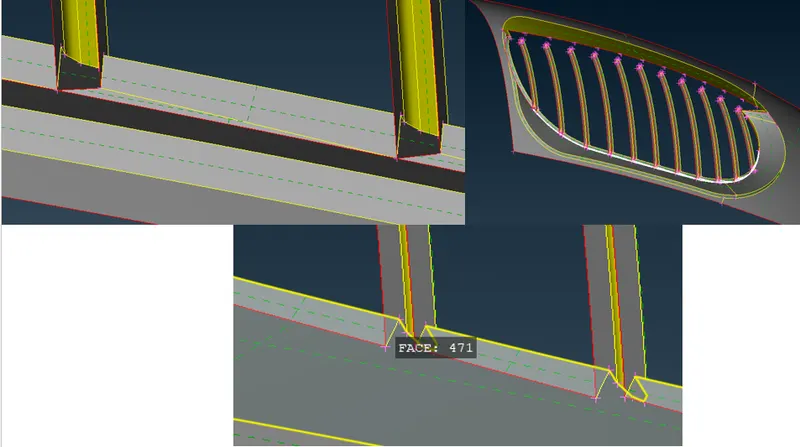
- Now we can go ahead and create new surfaces as shown below:
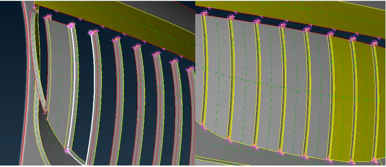
- Lastly we have to close the region.
>> Exploring the MULTI PROJECT option:
- This tool helps us to create multiple hot points with respect to local reference hot points.
- Select MULTI PROJECT option. (TOPO DECK >> HOT POINTS >> MULTI PROJECT).
- This solves the final piece off this part as shown below:
==============================================================================
Doorside feature cleanup:
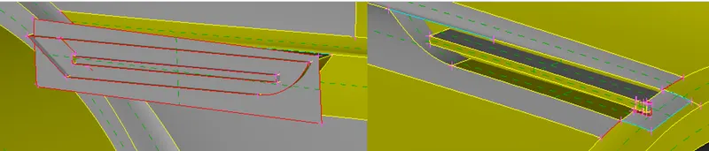
- As visible in the above picture, there are lot of single cons and triple cons with intersecting surfaces.
- We need to clean up those areas with appropriate tools.
>> Exploring the INTERSECT option:
- This tool is used when we see there are three surface meeting and not forming a triple con.
- Select INTERSECT option. (TOPO DECK >> FACES >> INTERSECT).
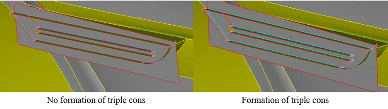
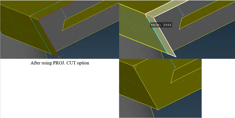
- There is face which needs to be trimmed, but the cons are incomplete.
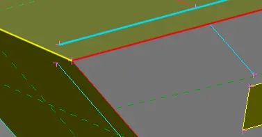
- With the help of PROJ. CUT option we can delete that surface.
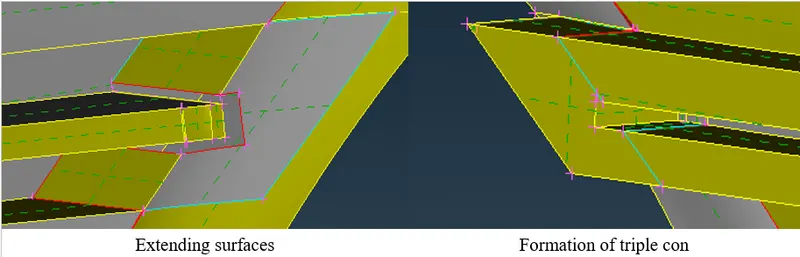
- Next is to extend few surfaces to eliminate the chances of formation of localized volume.
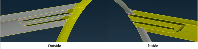
- Still some modification is required. It is done using EXTEND, UNIVERSAL DELETE, CUT etc and many other options.
- Finally, the end result should be some what like as shown in the figure below:
==============================================================================
Mirror clean up:
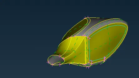
- Objective here is to remove the triple cons.
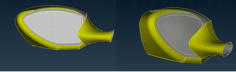
- As you can see there are no triple cons present.
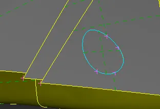
- Since we do not want localized volume to be formed, we must delete this region.
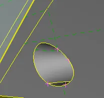
- The clean up mirror is done.
==============================================================================
Tire clean up:
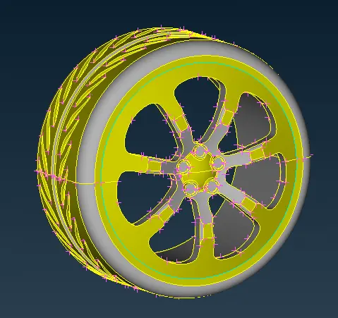
- We will be removing triple cons and overlapping surfaces if present.
- This can be done by hiding few surfaces and deleting unecessary surfaces using UNIVERSAL DELETE option.
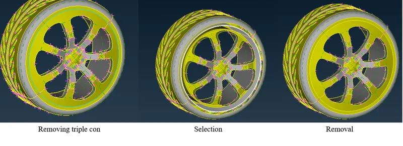
- Similarly procedure is for the second tire.
==============================================================================
Rear car clean up:
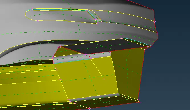
- Triple cons are visible. Simply delete with UNIVERSAL DELETE option.
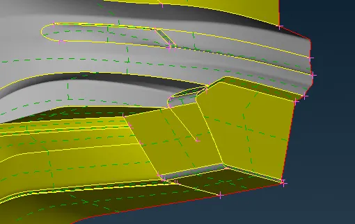
- The rectified figure can be found below:
==============================================================================
Floor clean up:
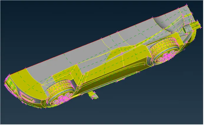
- There are lot of surfaces penetrating into different surfaces.
- The objective here is to removme those surfaces.
- This can be done using UNIVERSAL DELETE option.
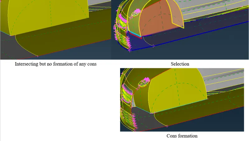
- If any surfaces meet and do not form any cons, then it is best prcatice to perform INTERSECT option. (TOPO DECK >> FACES >>INTERSECT).
>> Exploring CONS2CURVE option:
- This tools helps in creating curves out of existing cons.
- Objective here is to leave footprints for later use.
- Select CONS2CURVE option. (TOPO DECK >> CURVES >> CONS2CURVE).
- It will change the con colour to purple.

- There are lot of uneven surfaces which needs to be deleted.
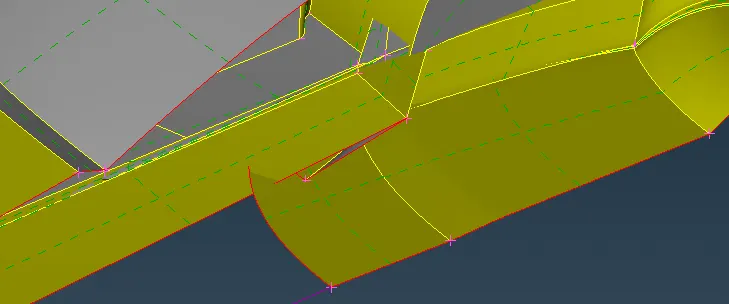
- Since there are lot of surfaces intersecting and not forming an cons, we must use INTERSECT option.
- Select INTERSECT option. (TOPO DECK >> FACES >> INTERSECT).
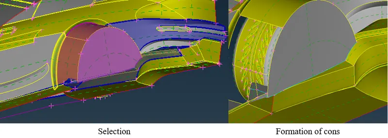
- Comparing befor and after of the floor, the after is much cleaner and has les overlapped surfaces as seen in the below figure:
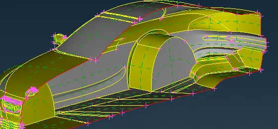
- This concludes the topology clean up of each and every part.
==============================================================================
Assigning PIDs:
- The next phase of the pre-processing is to assign PIDs to respective component.
- This allows you to work with the model fluently without any chances of facing any error or creating confusion over similar looking parts.
- Figure below shows the default PIDs assigned to the component:
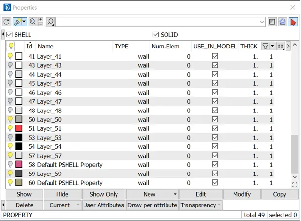
- To create new PID, right click and you will see NEW option. Selecting NEW, will allow you to set and apply PIDs.
- Some created PIDS are shown below:
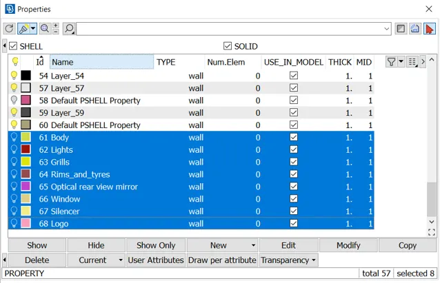
- PIDs highlighted in blue are newly created PIDs.
- Inorder to APPLY PIDs, we will isolate the component and then assign the PIDs.
- For example, in order to assign the Logo PID, we will isolate the logo and then assign it by right clicking on logo and select APPLY.
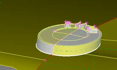
- After assigning the bulb will turn on.
- Similar is the procedure for assigning other PIDs.
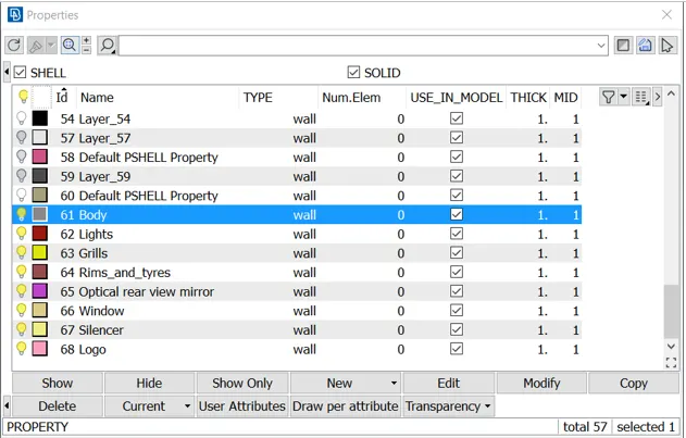
- As seen in above figure, all the newly created PIDs have glowing bulb, which means all are assigned properly.
- Now next step is to delete the default created PIDs by ANSA.
- This can be done by selecting COMPRESS option present in ribbon at top left corner.
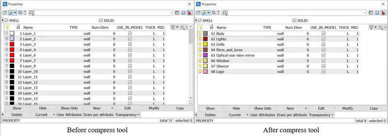
- This is the end of assigning PIDs.
==============================================================================
Meshing:
>> Exploring the QUALITY CRITERIA option:
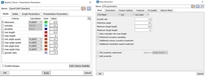
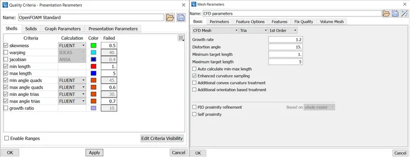
- This tool allows us to set set the quality of mesh before hand.
- Later it meshes the surface/volume maintaining the bounds of the specified quality criteria.
- Some of the quality checks can be found in the below figure:
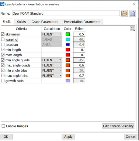
- Lets say the element skewness is less than 0.5 (see above figure), then it will show that particular element in green colour.
- Next step is to assign mesh elements part by part but one at a time.
- Below is the list of target lengths:
- Body - 3 mm
- Lights - 4 mm
- Grills - 1 mm
- Rims and Tyres - 2 mm
- Optical Rear view mirror - 2 mm
- Window - 2 mm
- Silencer - 3 mm
- Logo - 1 mm
==============================================================================
Meshing the logo:
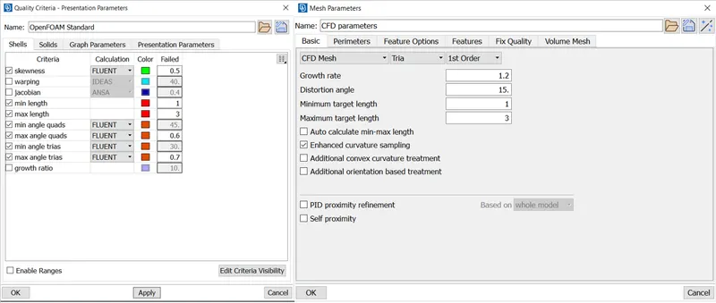
- Before initiating the mesh, MESH PARAMETER and QUALITY CRITERIA must be assigned.
- Target Length = 1 mm
- Maximum Length = 2 mm
- Minimum Length = 0.4 mm
- Select LENGTH option. Assign same mesh length value for both perimeter and macros (MESH DECK >> PERIMETERS >> LENGTH).
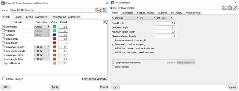
- Select SPOT MESH option. (MESH DECK >> MESH >> MESH GENERATION).
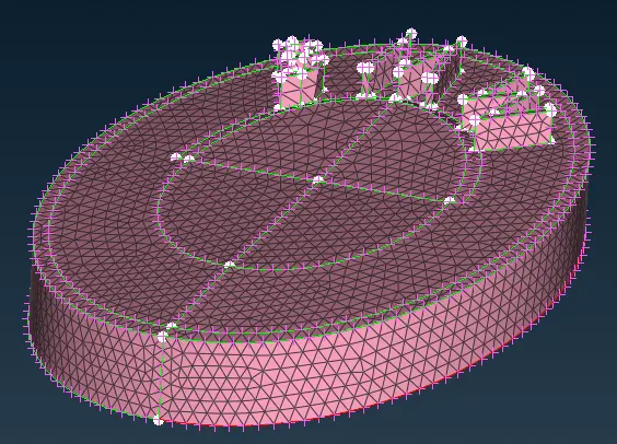
- In order to check quality criteria matches or not, we must enable HIDDEN mode.
- At the left hand side one can see the criteria.
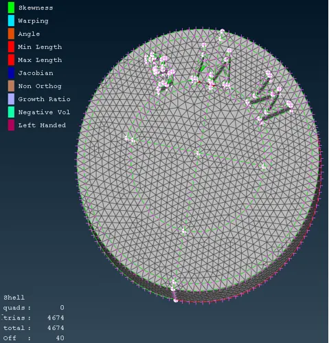
- Off elements can be removed using RECONSTRUCT option.
- Select RECONSTRUCT option. (MESH DECK >> SHELL MESH >>RECONSTRUCT).
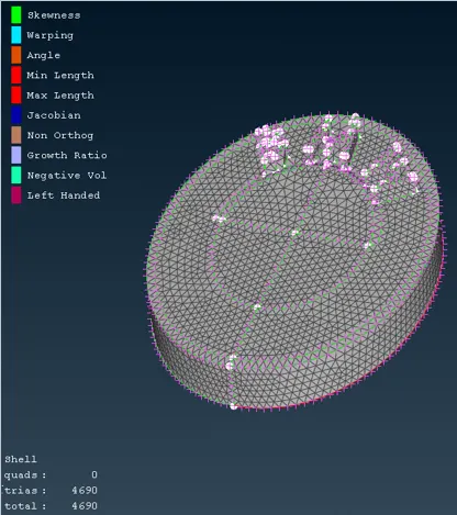
- As seen, there are no off elements present after using RECONSTRUCT option.
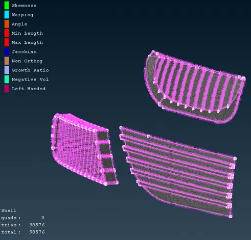
Meshing the Grills:
- Before initiating the mesh, MESH PARAMETER and QUALITY CRITERIA must be assigned.
- Target Length = 1 mm
- Maximum Length = 2 mm
- Minimum Length = 0.3 mm
- Select LENGTH option. Assign same mesh length value for both perimeter and macros (MESH DECK >> PERIMETERS >> LENGTH).
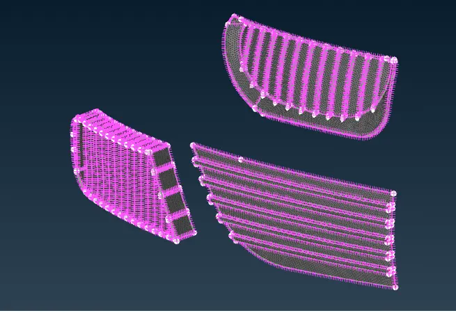
- Clear the off elements using RECONSTRUCT option.
Meshing the Window:
- Before initiating the mesh, MESH PARAMETER and QUALITY CRITERIA must be assigned.
- Target Length = 2 mm
- Maximum Length = 3 mm
- Minimum Length = 1 mm
- Select LENGTH option. Assign same mesh length value for both perimeter and macros (MESH DECK >> PERIMETERS >> LENGTH).
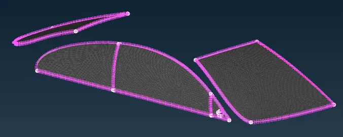
- Mesh can be seen below:
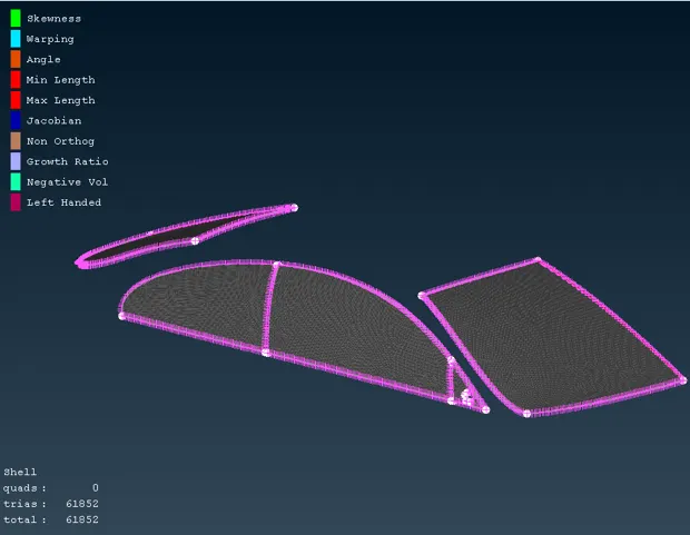
- No presence of off elements. As it can be seen in the below figure:
Meshing the Lights:
- Before initiating the mesh, MESH PARAMETER and QUALITY CRITERIA must be assigned.
- Target Length = 4 mm
- Maximum Length = 5 mm
- Minimum Length = 3 mm
- Select LENGTH option. Assign same mesh length value for both perimeter and macros (MESH DECK >> PERIMETERS >> LENGTH).
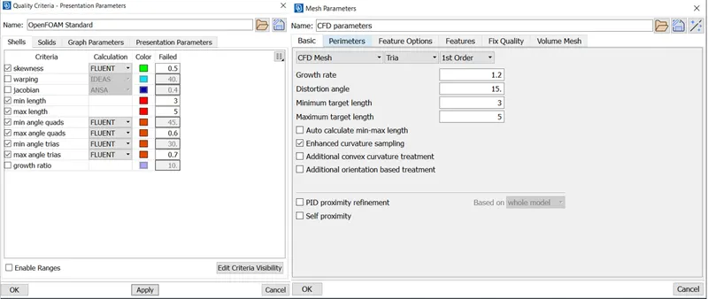
- Mesh can be seen below:
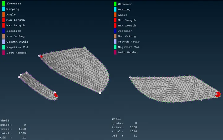
- Number of off elements are 11.
- This can be resolved by using SPLIT option. (MESH DECK >> ELEMENTS >> SPLIT).
- By clicking the desired edge it will split that edge.
- If this does not work, use SMOOTH option. (MESH DECK >> SHELL MESH >> SMOOTH).
- Even this does not work then use MOVE option. (MESH DECK >> GRIDS >> MOVE).
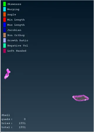
- No off elements are present.
Meshing the Rims and Tyres:
- Before initiating the mesh, MESH PARAMETER and QUALITY CRITERIA must be assigned.
- Target Length = 2 mm
- Maximum Length = 3 mm
- Minimum Length = 1 mm
- Select LENGTH option. Assign same mesh length value for both perimeter and macros (MESH DECK >> PERIMETERS >> LENGTH).
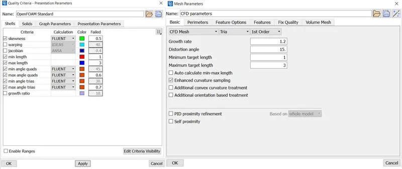
- Mesh can be seen below:
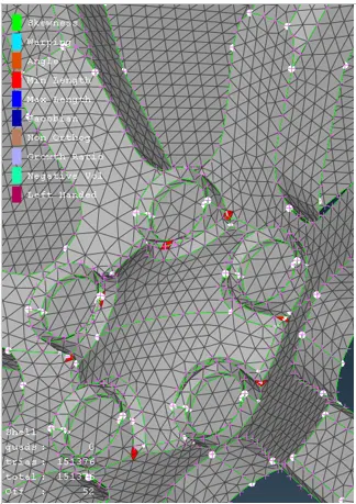
- There are lot of off elements near the nut bolt area.
- Can be resolved by performing topo clean up.
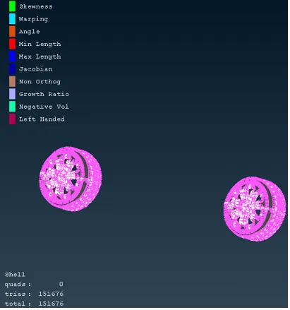
- No off elements are present.
Meshing the Silencer:
- Before initiating the mesh, MESH PARAMETER and QUALITY CRITERIA must be assigned.
- Target Length = 3 mm
- Maximum Length = 5 mm
- Minimum Length = 1 mm
- Select LENGTH option. Assign same mesh length value for both perimeter and macros (MESH DECK >> PERIMETERS >> LENGTH).
- Mesh can be seen below:
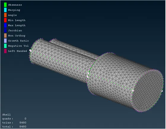
- It does not have any off elements.
Meshing the Rear View Mirror:
- Before initiating the mesh, MESH PARAMETER and QUALITY CRITERIA must be assigned.
- Target Length = 2 mm
- Maximum Length = 3 mm
- Minimum Length = 1 mm
- Select LENGTH option. Assign same mesh length value for both perimeter and macros (MESH DECK >> PERIMETERS >> LENGTH).
- Mesh can be seen below:
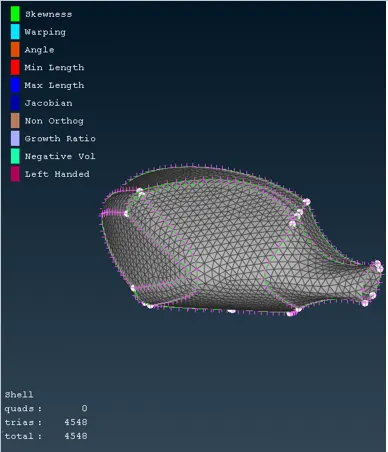
- There are no off elements.
Meshing the Body:
- Before initiating the mesh, MESH PARAMETER and QUALITY CRITERIA must be assigned.
- Target Length = 3 mm
- Maximum Length = 5 mm
- Minimum Length = 1 mm
- Select LENGTH option. Assign same mesh length value for both perimeter and macros (MESH DECK >> PERIMETERS >> LENGTH).
- While using perimeters option, deselect the edges in conjucntion with the body PID.
- It will assure the mesh of the other elements do not vanish.
- To remove the off elements, one must assign the global element criteria.
- Considering the smalllest feature in the car and possible areas of skewness formation.
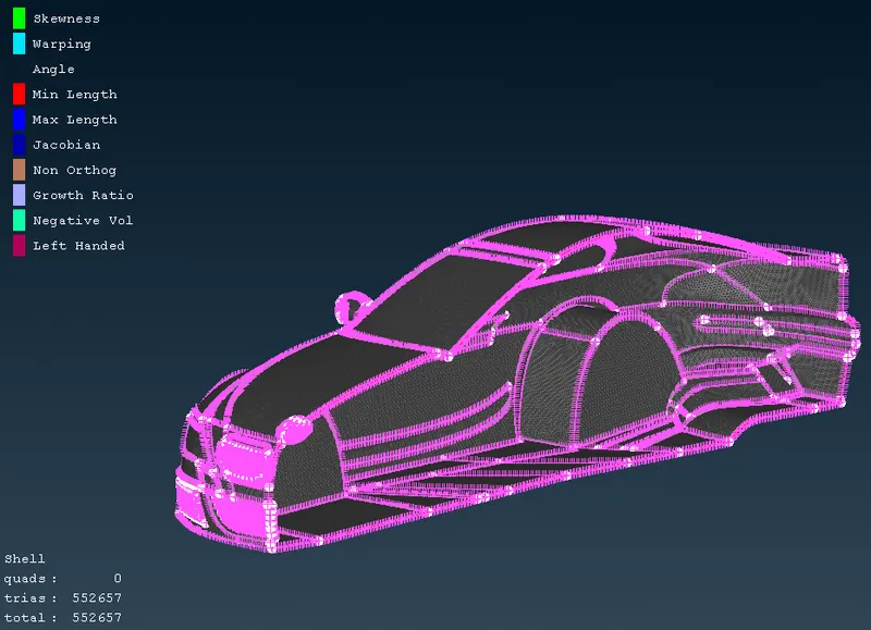
- Finally, there are no off elements present and we can head to create wind tunnel.
- Surface meshing of PIDs end here.
==============================================================================
Symmetry of the model:
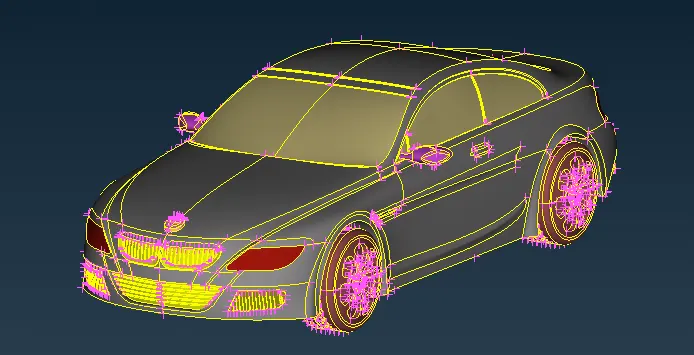
- Select proper view for proper selection of the model.
- Select TRANSFORM option present at the right hand side of the viewport.
- Select COPY option. It will ask you to select the entities to copy.
- Select the entire car except the logo.
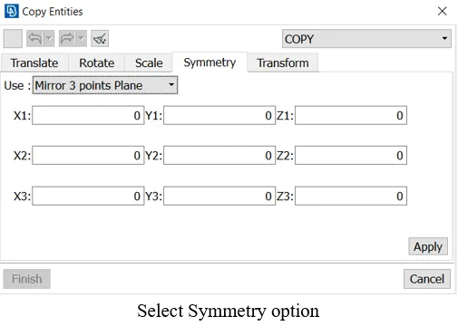
- Select any three point along the line representing as the symmetry plane.
- Take a peek at the figure below, representing the entire car.
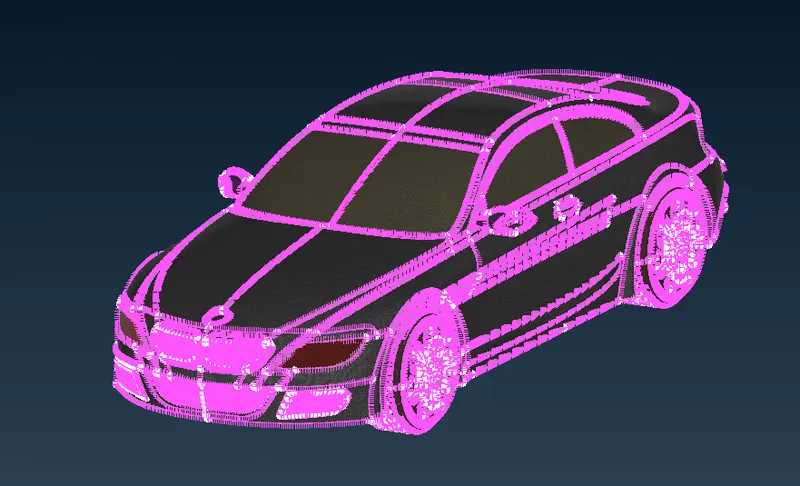
- Next step is to create Wind Tunnel.
==============================================================================
Wind Tunnel:
- There are few standards to be followed to make a wind tunnel.
>> Exploring the RELATIVE option:
- This tool helps in creating a point relative to an already selected point in either x,y or z direction.
- Select RELATIVE option. (TOPO DECK >> POINTS >> RELATIVE).
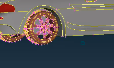
- A point is created.
- With the similar approach we can create more points using RELATIVE option.
- Front Point = 5854 mm.
- Rear Point = 8410 mm.
- Top Point 3900 mm from top point.
- Side Point = 1300 for both sides.
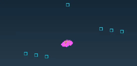
- These points can be used to create curves.
- Select CREATE option. (TOPO DECK >> CURVES >> CREATE).
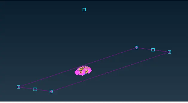
- Using this one can create surface/face.
>> Exploring the OFFSET option:
- This tool helps in creating a surface/face offset from selected entity.
- Select OFFSET option. (TOPO DECK >> FACES >> OFFSET).
- Offset value = 4275 mm.
- Finally, the wind tunnel looks like this:
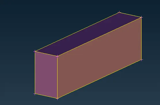
Meshing the Wind Tunnel:
- As we are closer to the car, we expect to have a finner mesh and as we move away from the car, we expect to have a coarser mesh.
- Turn off the maximum and minimum length quality critera
- Top surface = 100 mm.
- Bottom surface = 20 mm.
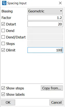
- For side, inlet and outlet we have to give variable mesh length.
- This can be done by using SPACING option.
- Select SPACING option. (MESH DECK >> PERIMETERS >> SPACING).
- It will ask few inputs. Please refer below figure:
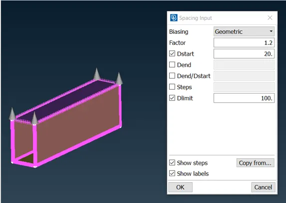
- Select the vertical edges of the box as shown in the figure below:
- Finally the mesh in the front and side looks like the figure below (same is for other wind tunnel surfaces):
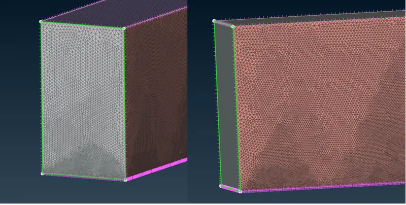
- Finally there are no off elements and all the surfaces are meshed.
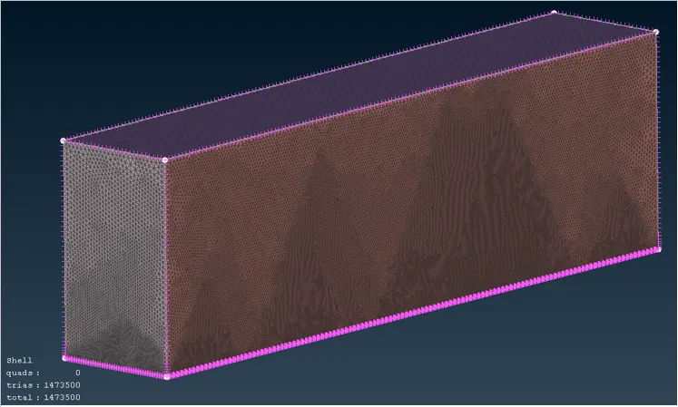
NOTE : In this task volumetric mesh is not performed as it will take lot of time to mesh. Hence the discussion is also not done.
==============================================================================
Conclusion:
- Learnt how to create a half model.
- Topology clean up part by part with the help of different tools.
- Assigning appropriate PIDs.
- Meshing PIDs one at a time.
- Deligating with off elements and it rectification using different tool approach.
- Creating symmety of the half model.
- Creating wind tunnel and assigning relevent mesh length and variable mesh length.