Week 4 Challenge : CFD Meshing for BMW car
AIM:
To study and perform surface meshing on BMW car and also to create a wind tunnel(perform surface meshing).
OBJECTIVE:
For the given BMW car first, we have to solve the geometrical errors on the half portion and perform them with the given Target length and element Quality criteria(TRIA). Once the meshing of the half model is done perform the symmetry to another side and also take care of the meshing size element error and off element. Finally, we are creating the wind tunnel for the BMW car model to do the surface meshing for the given target length and element quality type.
TOOLS USED:
- FILL HOLE
- HOT POINTS(INSERT)
- TRANSFORM(SYMMETRY)
- TOPO
- CONS(PROJECT)
- CONS(RELEASE)
- FACES(EXTEND)
- DELETE
- FACE(FITTED)
- FACE(PLANNER)
- FACES(CUT)
- FACES(OFFSET)
- FACES(ORIENT)
- CURVES(CREATE)
- CURVES(DELETE)
- CURVES(CONS2CURVE)
- AUXILIARIES(FINE)
- PERIMETER(LENGTH AND MACROS)
- PERIMETER(SPACING)
- MESH GENERATION(ERASE)
- SHELL MESH(RECONSTRUCT)
- SHELL MESH(SMOOTH)
- ELEMENTS(SPLIT)
- GRIDS(MOVE)
- GRIDS(PASTE)
- SPOT MESH
- CFD MESH
- UNFREEZE
- V MESH( VOLUME=>DEFINE)
- VOLUMES(LIST)
PROCEDURE:
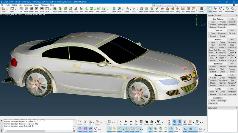
- Initially, we get a BMW car model and we convert from the PID option to the ENT option so we get the below-shown figure.
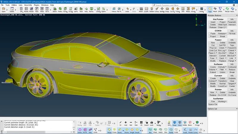
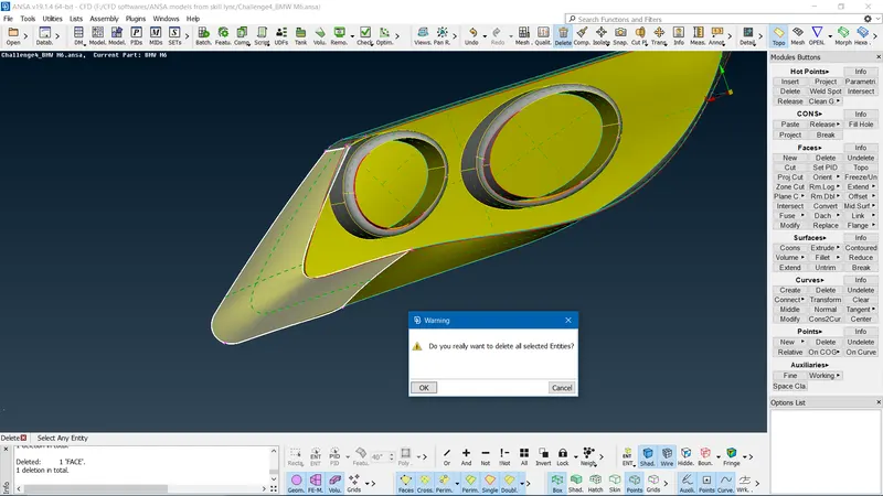
- As we can see from the above figure we can see single cons and triple cons issues also intersection errors once the checks manager is done on the entire car model. The first step of proceeding with the car models taking care of the geometrical error of the entire car which would be a tedious process for solving the entire car model. The best solution is to delete the half symmetrical surface solve for geometrical errors and do surface mesh then copy the solved half model to the other surface. But first, we delete half the surface of the car(Surface with minimal errors) as shown below figure.
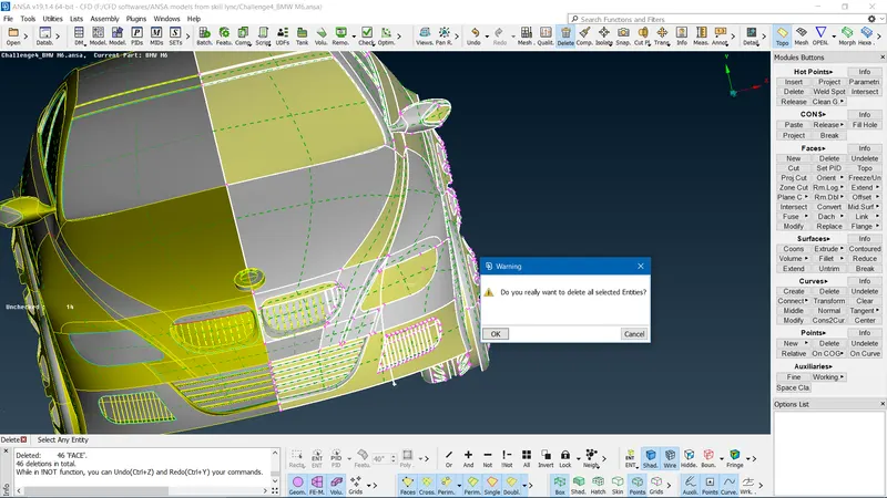
- Once the half surface of the car model is deleted we do the checks managers we find out numerous errors such as single con, triple con, intersections, and overlapping surface. These errors have to be solved one after the other in order to get clean geometry for meshing.
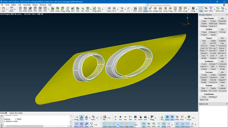
- First, I started with the front headlights since there are many triple cons issues as shown below.
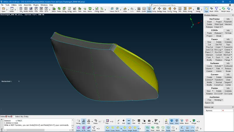
- With headlights, we need outer important surfaces so we determine the necessary surface first by using the NOT option and studying the adjacent surfaces(If it is confusing to see the front light with other entities we isolate them by using the NOT option and INVERT option ). Once it's determined we DELETE the option to delete the unwanted surfaces to clear the geometry error issues as shown below.
- Once the geometry clean-up is done geometry check managers are to check for the errors, if there are no errors we proceed with the alternative parts of the car for cleaning up the geometry.
- Note that the main purpose of deleting unwanted surfaces is to prevent the meshing complexity of the car model.
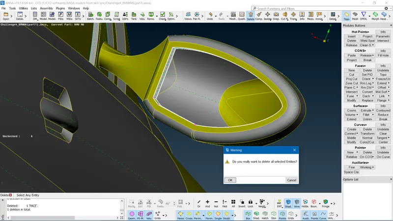
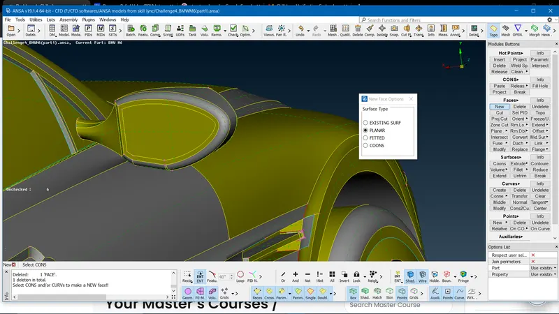
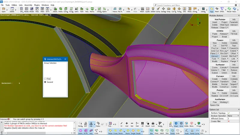
- In the Optical Rear view mirror, we can find there are unwanted surfaces for meshing first we delete these surfaces and use FACES==>NEW==>PLANNAR option==>ok to create a simple plane surface. Also, we find the intersection error between the Optical Rear view mirror surface and car body this is taken care of by using the FACES==>INTESECT option to select respective bodies==>ok. Finally, use the CONS==>PROJECT option==> to select the cons and surface to be projected and delete the unwanted surface (as shown below figures).
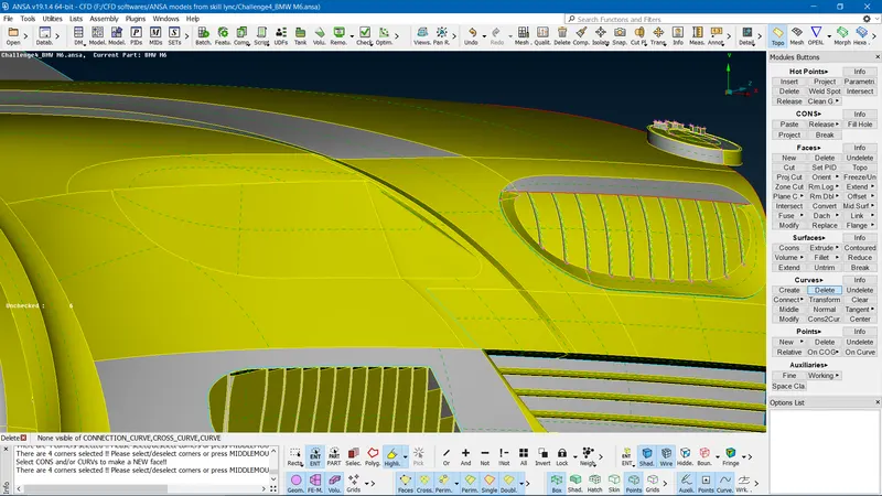
- Now as we go to the Top and Bottom grills add we find there are many intersections and triple con issues so this has to be taken one by one very consistently for getting better mesh quality on these surfaces.
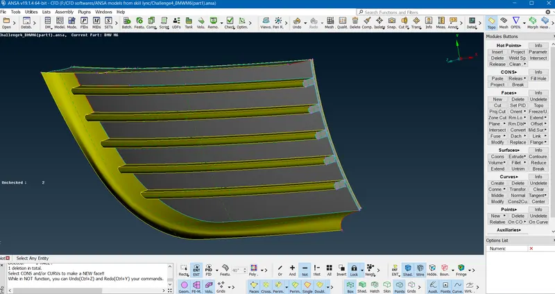
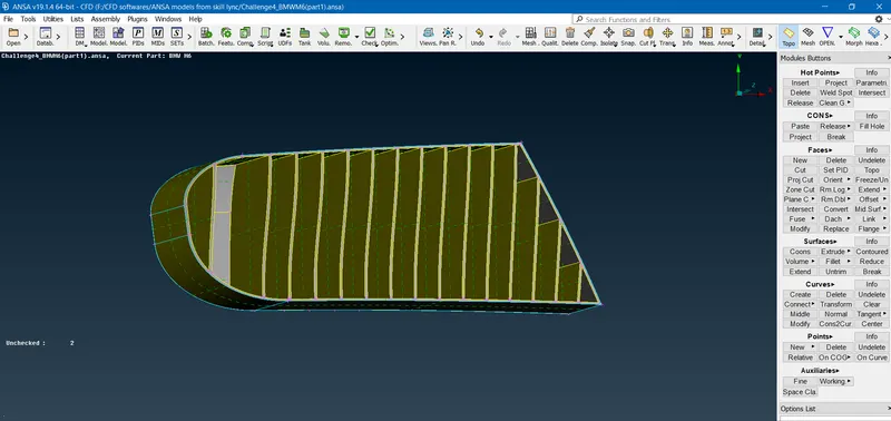
- On grills, the first step is to delete the unwanted surfaces to take of TRIPLE con issue.
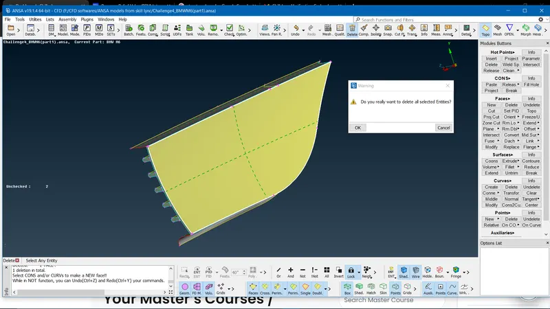
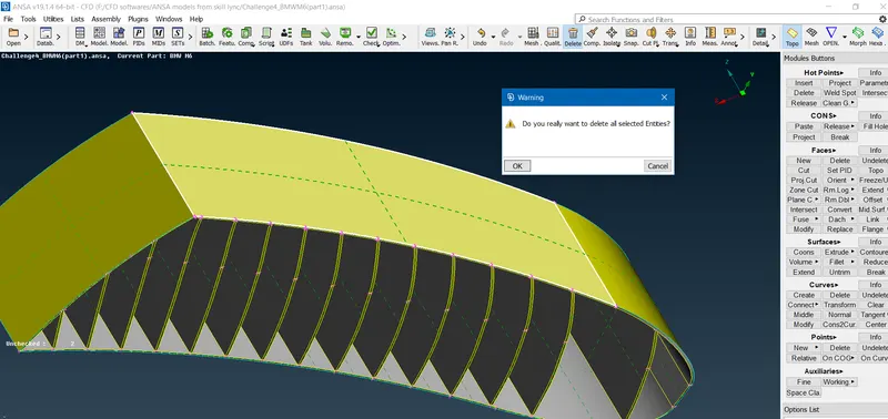
- Next, In the following step once the unwanted surfaces are deleted we create a suitable simple surface for meshing by using FACES==>NEW==>PLANNAR option==>ok. And the entire back surface of the grills is created to have air-tight geometry. This is done one by one and is a tedious process but good for surface meshing.
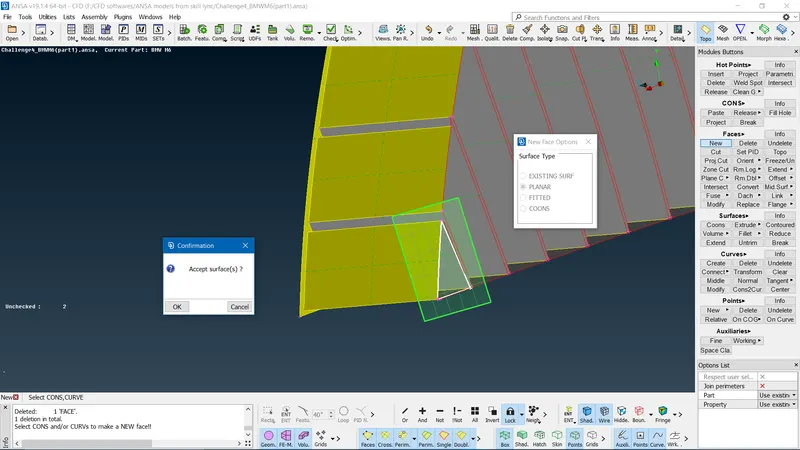
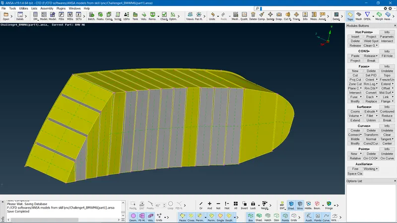
- For the top part of the grill geometry, we have to create an air-tight surface which is challenging(creating individual back covering components).
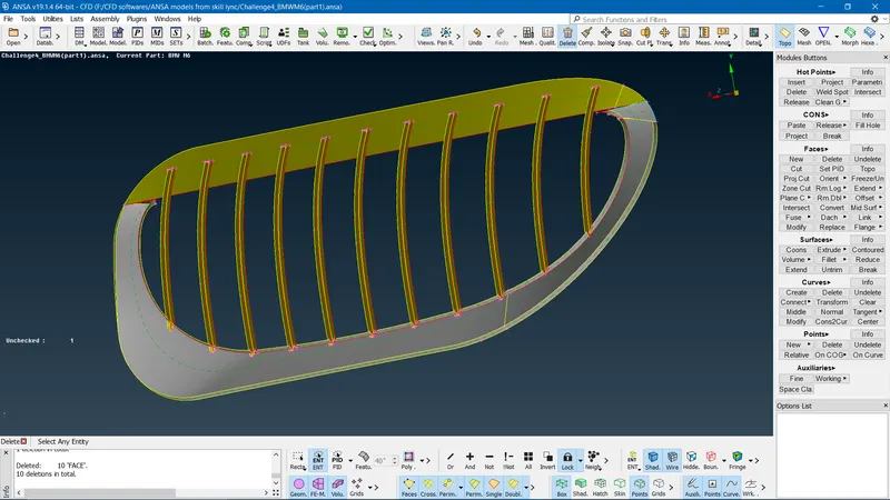
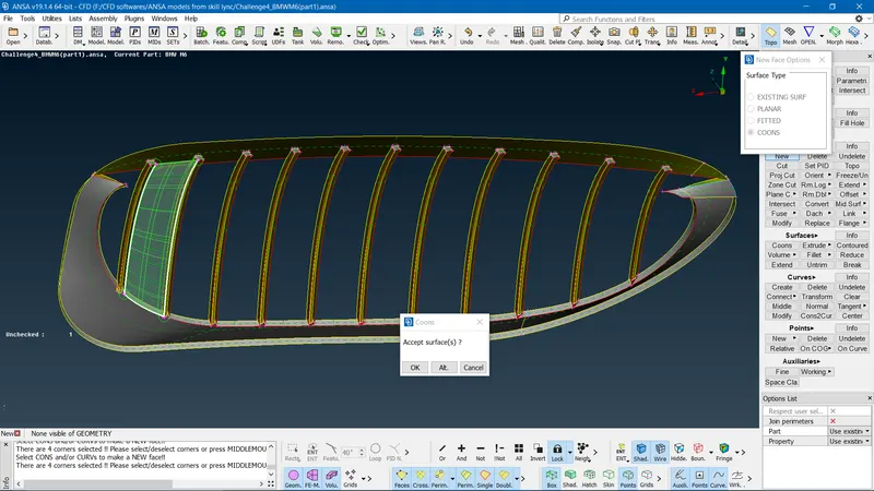
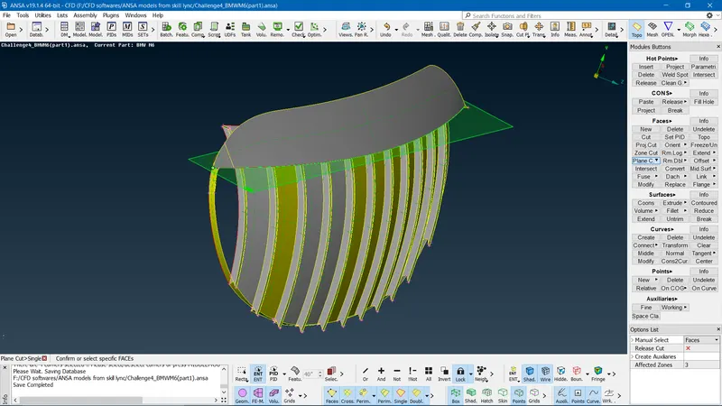
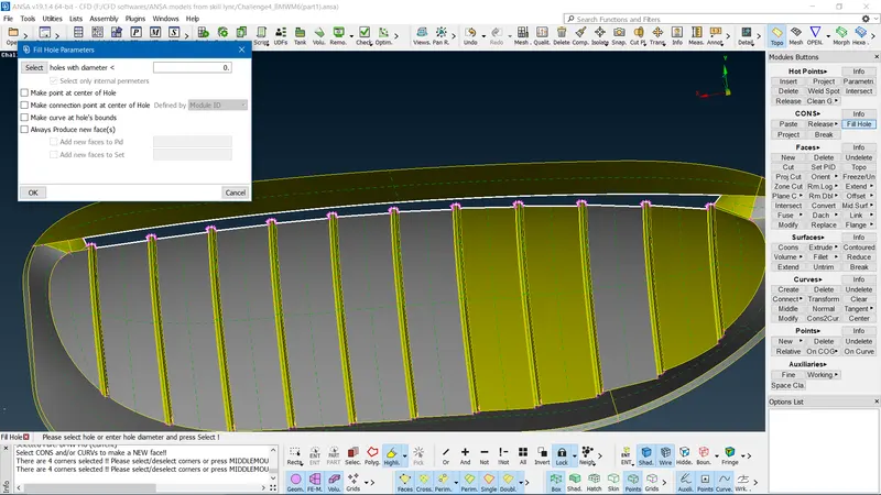
- Individual air-tight geometry is created one by one by using FACES==>NEW==>COONS option==>ok. Once the entire back surface of the grill is covered we notice there is an uneven surface so we do a clean plane cut by using FACES==>PLANE CUT==>select the respective HOT POINTS==>ok. Small single cons and triple con errors are taken care and geometry is created at the plane cut surface(By using drawing curves CURVES option, HOT POINTS INTERSECT option, PROJECT option) and finally use CONS==> FILL HOLE option as shown below.
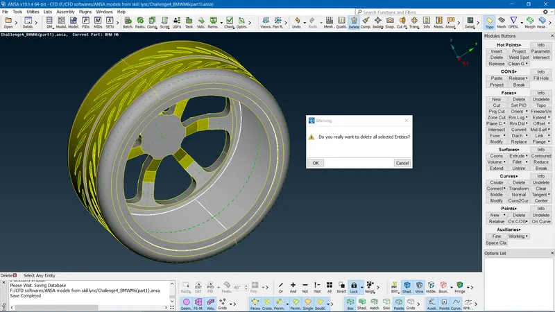
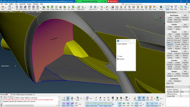
- The wheel is also taken care of by deleting the unwanted errors also intersection errors by using the FACES==>INTESECT option to select respective bodies==>ok.
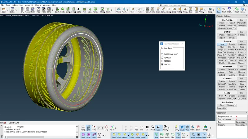
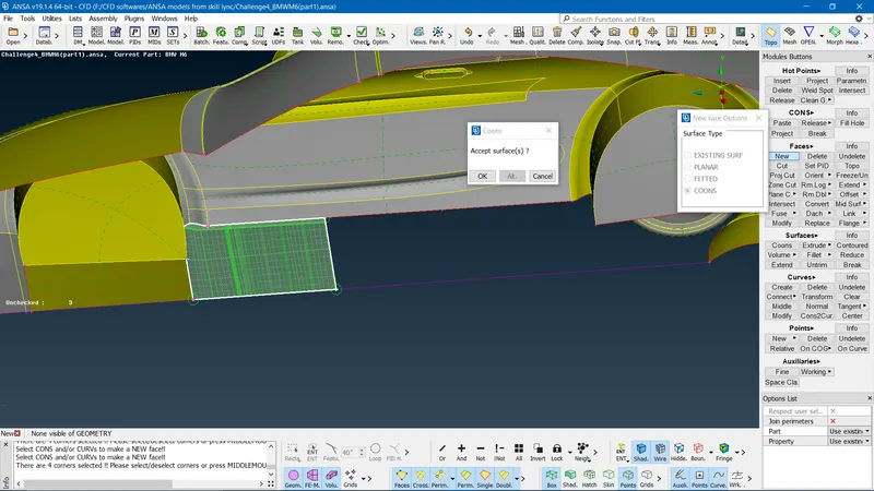
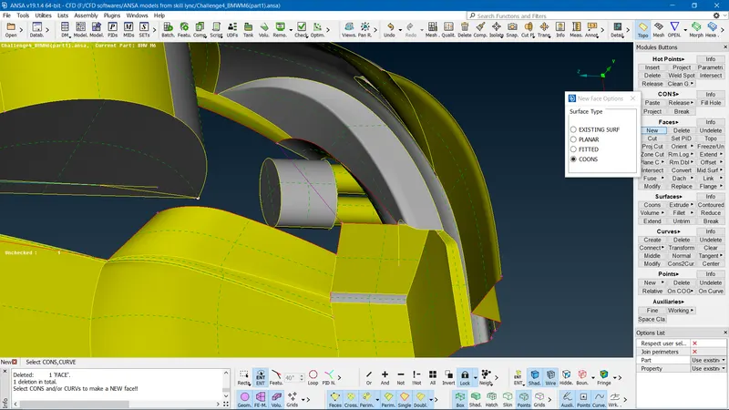
- Once the majority of the components of the car are free from respective errors we move on to the body of the car. The bottom body surface of the car is created to get a smooth plane surface which is created in ordered function by constructing curves(CURVES option) and creating faces using FACES==>NEW==>COONS option==>ok respectively(as shown below).
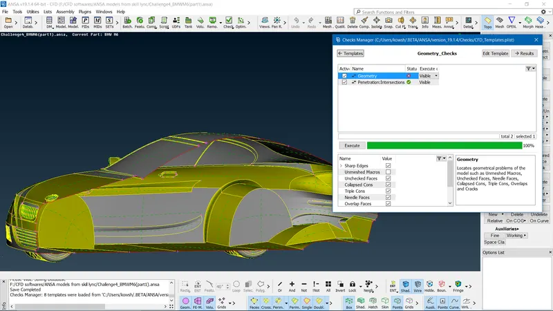
- Since we have cleaned up the entire half of the car model to have confirmation we do CHECH MANAGER to check for errors. We do get some single con error at the end cut surface of the car which is ok because we are going to do the symmetry option at the final stage and I get the following results.
- We create PIDs for individual components of the car by opening the PID option==>right clicking on Shell property==>create new shell property==>apply each component into the newly created component==>ok.
- Sometimes we get intersection errors this can be due to the quality of the geometry this can be resolved by increasing the quality of the geometry.
- So once we are finished with the geometrical cleanup we go for the meshing process. This is done by changing the TOPO option to the MESH option.
SURFACE MESHING THE BMW CAR
- For the surface meshing of the BMW car, we cannot select the entire car and mesh once and for all because we have different target lengths given so according to the target length and type of meshing we have to mesh each and every component of the car separately.
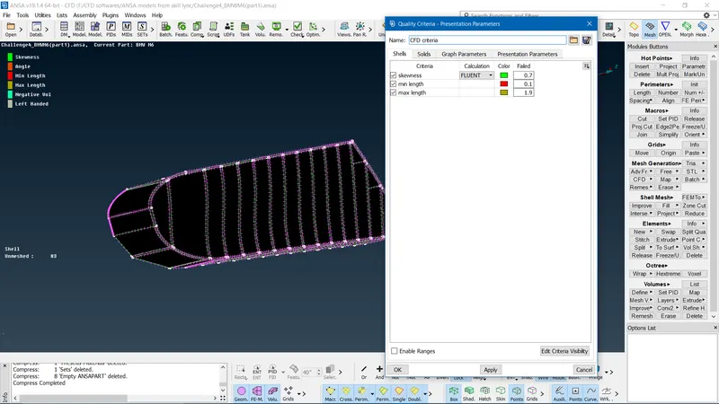
- First, we edit the QUALITY CRITERIA by selecting the required parameters such as MINIMUM AND MAXIMUM LENGTH ALSO SKEWNESS.
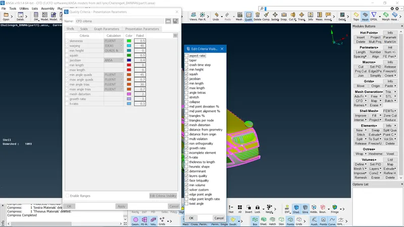
- The following step would be to predict which type of meshing(SPOT MESH or CFD MESH) would be good enough for the individual components.
- To get finner mesh for complex geometry we use CFD mesh whereas SPOT mesh is used for simple geometry.
- Steps for CFD MESH
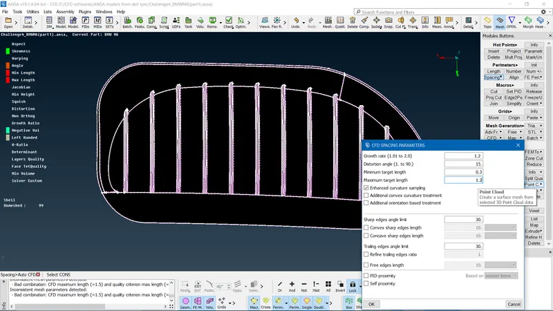
- Initially, we take the component we give the target length under PARAMETER==>SPACING OPTION==> select AUTO CFD option we get pop up window==> give CFD spacing parameters such(PERIMETER AND MACROS individually)==>specify minimum and maximum target lengths==>ok.
- Under MESH GENERATION==>Select CFD option==> visible.
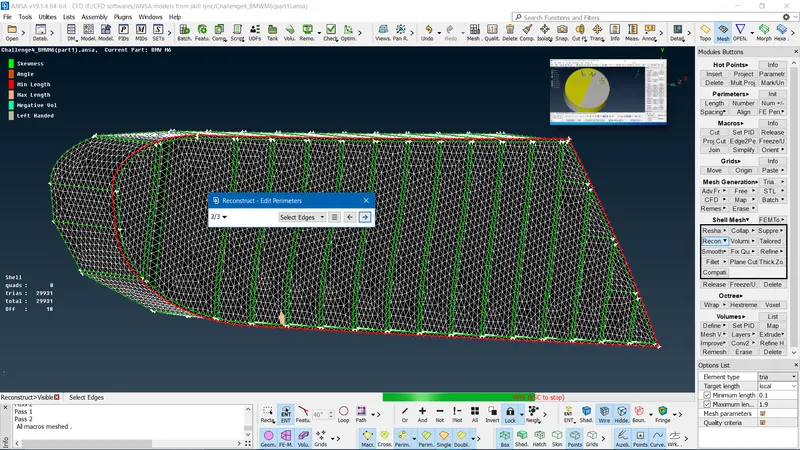
- If we get too many OFF elements we do reconstruct by going to the SHELL MESH option ==>select RECONSTRUCT option==>select visible==>ok.
- Still, if we get off elements where elements are failing for minimum/maximum/skewness we use various operations.
- Under GRIDS options==> select MOVE option==> select each node(This option is used to move individual nodes for our satisfaction).
- Under GRIDS options==> select PASTE option==> select two individual nodes(This option is used to intercept to nodal elements).
- Under ELEMENTS option==> select SPLIT option==> select the maximum nodal length(This option is used to split the element).
- Under MESH GENERATION==> select ERASE option ==>select surface or entire body(This is used to unmesh the component).
- If we get too many OFF elements we do reconstruct by going to the SHELL MESH option ==>select SMOOTH option==>select visible==>ok(To smooth the meshed surface).
- The following steps are repeated for all other components of the car till we get no off components in the meshed surface.
- Note there are off elements(minimum/maximum/skewness) errors at boundary surfaces of each part this ok because there is a difference in target length between the components hence this ok.
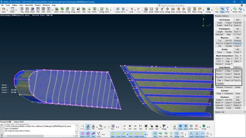
- Also once the meshing of a particular component is done we freeze the component by using the FREEZE option so that there are no changes that can be done to the component.
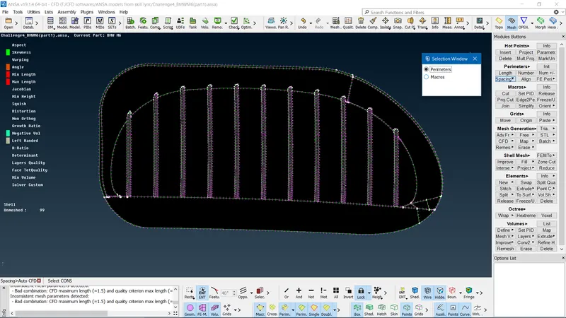
- Steps for SPOT MESH
- Initially in PARAMETERS option==> select LENGTH option==> pop up window(PERIMETER AND MACROS)==>Individually give target length==>ok.
- Under MESH GENERATION==> select SPOT MESH==> select the surface/body to be meshed.
- Here the spot meshing is done for the car body surface.
- If we get too many OFF elements we do reconstruct by going to the SHELL MESH option ==>select RECONSTRUCT option==>select visible==>ok.
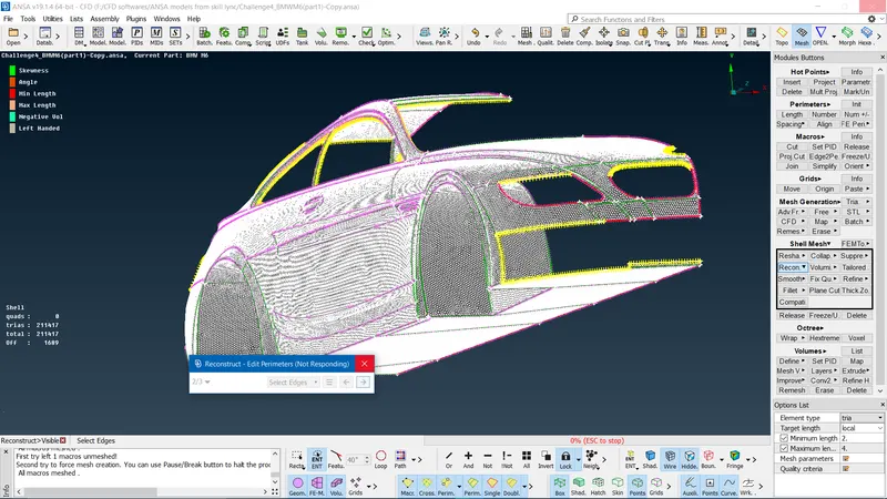
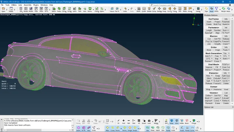
- Once the meshing is successfully done for the half surface of the BMW car we get the final meshed car model as shown below.
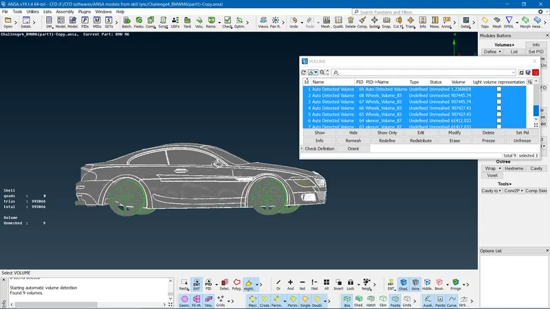
- The surface meshing of the BMW car is done next step is to detect the volume of the car to ensure the car volume is created or not. This is done by going to the VOLUME MESH option==>to predict the volume under the VOLUMES option==> select DEFINE option==>select dB ==> ok. we get the volume that is predicted for the car as shown below.
CREATING THE WIND TUNNEL AND PERFORMING SURFACE MESHING
- To create a wind tunnel first we have to predict the exact coordinates with respect to car length(x). The measured distance of the car x=1306mm.
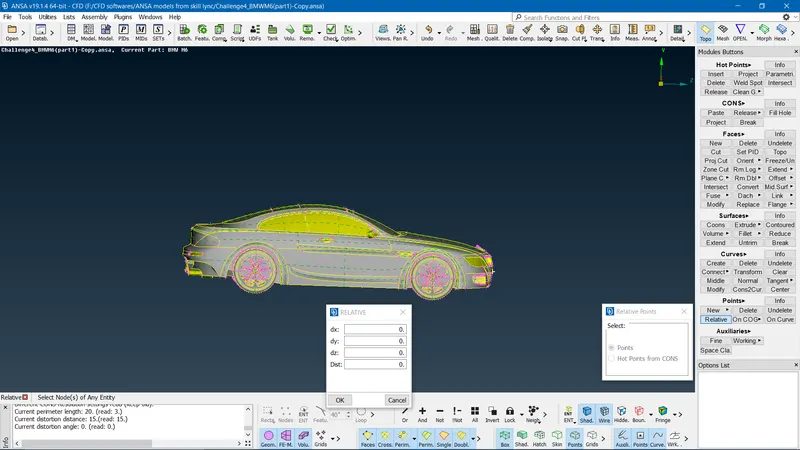
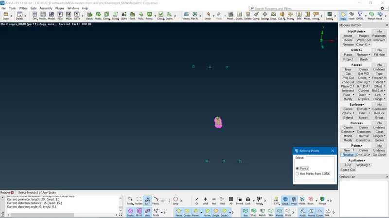
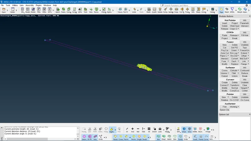
- Initially, we are creating relative points their measurement is given as frontal relative point is distance 4x, rear relative point distance is 6x, top relative point distance is 3x, sides relative point distance is x. These points are plotted with reference to the center plane of the car using POINTS==>select the RELATIVE option to calculate the distances ==> enter the values in their respective coordinates. Use the CURVE option to connect all the relative points created. Finally, we are creating the bottom surface of the wind tunnel by using FACES==>NEW==>COONS option==>ok.
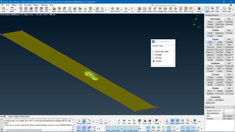
- The top surface of the wind tunnel is created by offsetting the bottom surface at a distance of ground clearance+height of the car+3x. This offsetting is done by using the OFFSET option==>select the nominal surface==>enter the offset distance==>ok. Once both surfaces are done create the side surfaces of the tunnel by using FACES==>NEW==>COONS option==>ok.
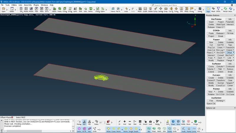
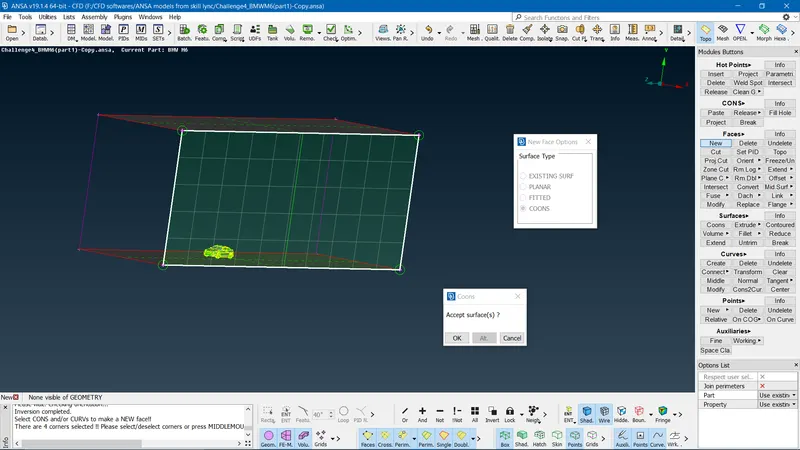
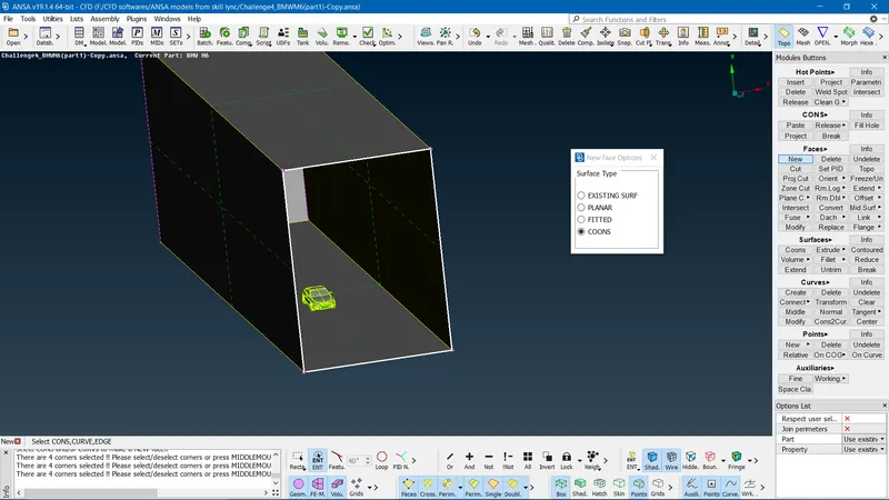
Once the wind tunnel is created we move on to the surface meshing of the wind tunnel
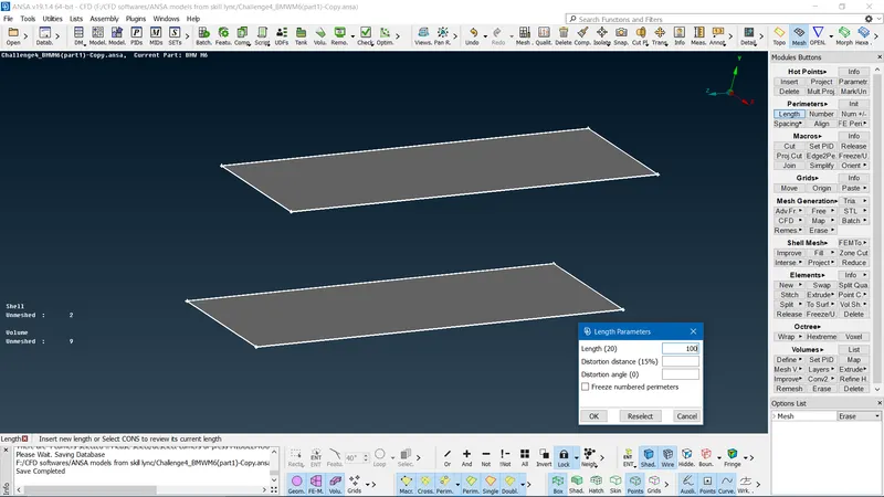
- Since the surface of the wind tunnel is simple we use SPOT MESH. Note the important point that we need refined fine mesh at the bottom surface of the wind tunnel because we have the car model and we need to study the characteristics and values affecting the surface of the car.
- Initial we mesh the top surface of the car by using PARAMETERS option==> select LENGTH option==> pop up window(PERIMETER AND MACROS)==>Individually give target length==>ok.
- Under MESH GENERATION==> select SPOT MESH==> select the surface/body to be meshed.
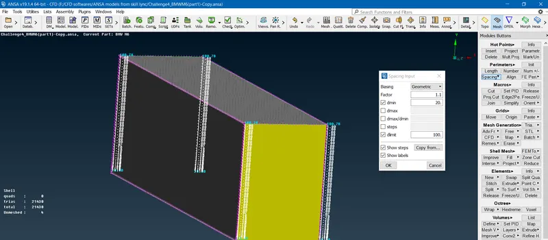
- Since the mesh should vary from bottom to top (20mm to 100mm) for side surfaces we use under the PERIMETER option==> select the SPACING manual option==> we get pop up window to assign factor=1.1, dmin=20mm, and dlimit=100mm==>select the edges==>ok. Finally SPOT MESH option.
- Once the sides of the wind tunnel mesh we notice that perimeter and macros are created respectively hence we do direct the SPOT mesh option to the bottom surface.
- Hence the surface mesh is created for the wind tunnel as shown below.
RESULT:
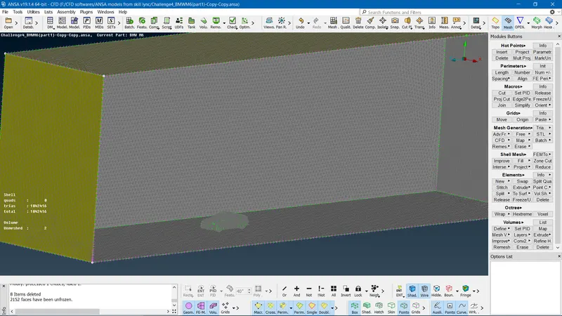
LINK FOR THE BMW CAR ANSA MODEL:
https://drive.google.com/file/d/1qdiHW__NgN--pBCQI1-SAzyOYmt5UEgL/view?usp=sharing
CONCLUSION:
I have successfully solved the geometrical errors for the given BMW car and surface meshed for different target lengths and element type(TRIA). So here we notice that spot mesh cannot be used for all the components with complicated geometry hence I have opted for CFD mesh. As we can see the surface meshed for components(mirror, wheels, silencer, optical mirror, windows, grills) of the car is an unstructured mesh with finner mesh elements. Spot mesh is used on the car body surface. And our main aim is to create an air-tight geometry to perform aerodynamic analysis on the external surface of the car so this can be checked in the V mesh option by how many volumes are present or created. Finally, I create a wind tunnel for the BMW car model and meshed the surface.