Week 4 Challenge : CFD Meshing for BMW car
TOOLS USED:
1. TOPO toolbar: Helps in fixing the topology of the model.
- Insert:It creates hot points on cons or 3d curves.
- Topo: This function automatically creates topological conditions between selected adjacent CONS.
- Project: It defines a new hot points or new cons as the projection of existing hotpoints or cons.
- Parametric:Defines new hot point on a existing curve or con parametrically.
- Multi-Project: It defines a multiple new hot points as the projection of existing hotpoints at a time.
- Cut: splits or joins existing faces.
- Intersect: Used to define the intersection between two surfaces penetrating each other.
- Create new surface
- Coons: This is an easy way to define a new surface by its boundary curves.
- Fitted: The FITTED option is used for the definition of a non-planar Face. The created Face fits to the selected boundaries.
- Conc2Curve: This function defines 3D-curves from existing CONS, shell/solid edges, Line Elements end Cross-sections.
- Relative: This function creates new 3D-points that lie on a given relative position from a number of selected points.
- Orient: It sets a uniform orientation direction to all visible Faces according to the orientation of the majority of the Faces.
2. Mesh toolbar : Helps in meshing using different mesh algorithm and mesh tools.
- Length: Helps in setting the element length on selected perimeters or macros.
- Spot mesh: It creates automatic mesh for macro and finite element shell mesh areas by using special meshing method for macro areas and gives better result than free mesh in case of weld joints.
- Reconstruct: Performs re-meshing after examining existing mesh to correct problematic areas and optimize the overall quality of the mesh according to the mesh parameters.
- Spacing: Manual control of nodal spacing and distribution on perimeter segment. It can be used when there are varying mesh lengths.
- Split: It helps in spliting quadrilateral and triangular shell elements into smaller ones.
- Move:Help to mode nodes.
- Orgin: This function moves the selected grid points to their original position
3.V. Mesh toolbar: Has tools for volumetric mesh.
- Volume>Define: It automatically defines multiple volumes using already meshed macros or FE-model mesh.
- List: Activates list function
4. Set PID: This function assigns selected Faces, Shells or Groups of entities to an existing or new PID.
5.Universal Delete: The delete option is used to delete all the entities which are selected.
6. Loop: Helps to select multiple cons connected to each other at a time.
7. Fill Holes: Fills the holes and holes present in the model.
8. Compress: Compress files size by removing unwanted and unused entities.
9.Wire: To see model in wire frame mode.
10. These tools are used to see entities or hide entities and are very useful while inspecting then model for errors.
Not tool: Use to hide a surfaces or PID.
And tool: Helps to find the neihbouring surface belonging to selected con or PID.
!Not tool: Help in isolating multiple surfaces and PIDs.
Or tool: Isolating a surface or a PID.
Lock tool: To lock isolated PIDs or surfaces.
Neighbour: To see the neighbouring surfaces or PIDs.
11.Cross-Hatches: Activate and deactivate cross hatches on the model surfaces.
12.PID properties: It is helpful to name the PIDs present in the model and facilitates property management.
13. Compress Tool: To remove alll unnecessary PIDs in PID manager.
14. Measure tool: Helps to measure distances and dimension lengths.
15.Transform Tool: It is used to Translate, Rotate, Transform, Scale, Symmetry or Mirror selected entities (Faces, Points, Elements etc).
16.Cut Plane: It helps to cut the plane as per required orientation.
AIM:
- To check and solve all geometrical errors on half portion and assign appropriate PIDs.
- To perform meshing with the given Target length and element quality criteria.
- To recreate the full car model using symmetry.
- To create wind tunnel and volumetric mesh with tetra elements.
SOLUTION:
Model Given:
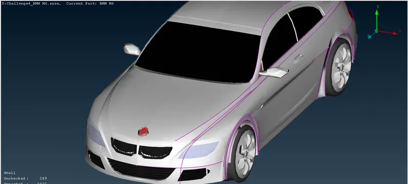
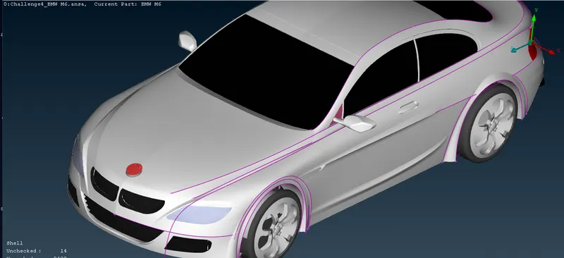
The car components have low con resolution. To fix it we will use Mesh>Perimeter>Length\
Setting Perimeter and macros values to 1mm.
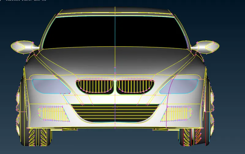
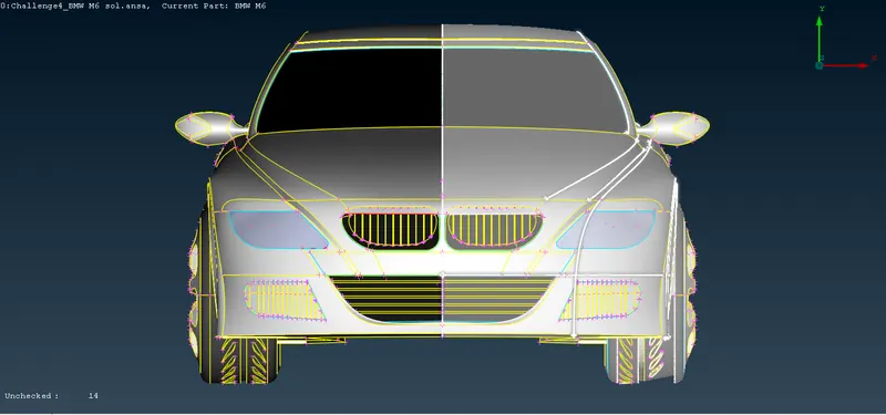
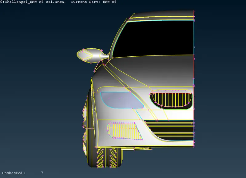
As the car is symmetrical except logo use Not tool to hide logo and delete the half of the car from front view:
Now usig Delete tool to remove symmetrical half of the car.
Topo Cleanup:
Fixing the headlight as there is a triple con present.
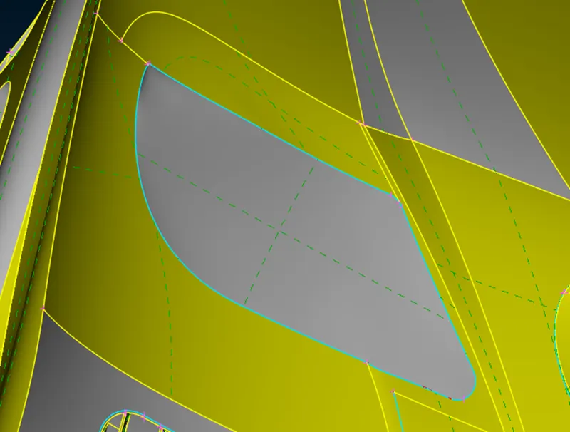
After deleting unnecessary entities of headlight :
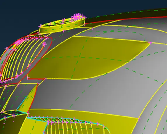
Single cons is found that can be fixed using paste tool and removing the triple con seen in the wireframe mode by deleting extra surface:
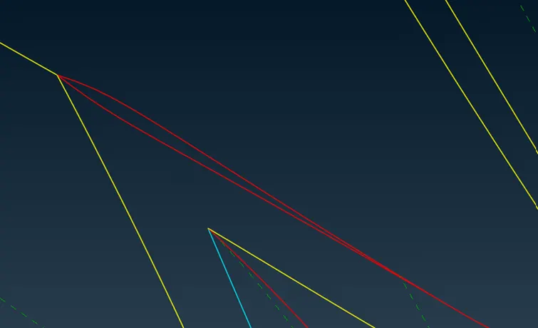
Now, moving to the Grilles:
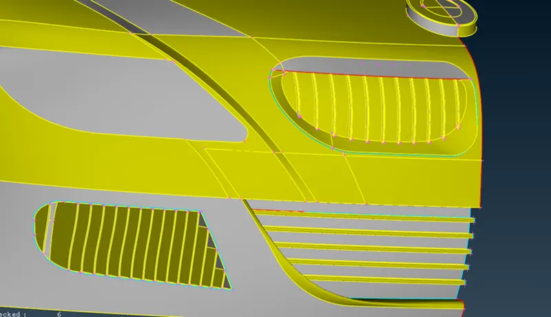
Inspecting for single cons and triple cons:
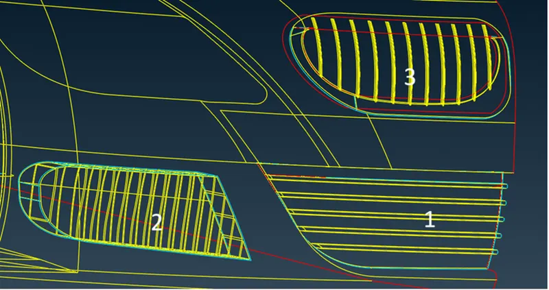
Working on Grilles-1's single cons, triple cons and extra surfaces :
Tools used to patch the surface: Delete, Cons>Paste,Cons>Project, Hot Points>Delete, Faces>cut, Faces>New
(a)Isolating Grilles-1
And deleting the side surfaces of all fins.
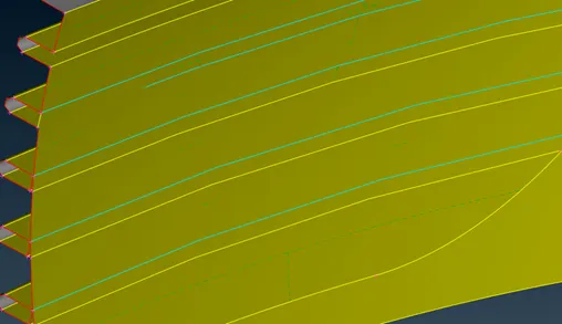
(b) Deleting the entities from the inside of the grill-1 by using delete tool.
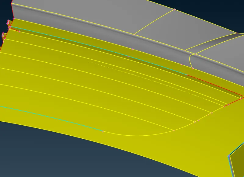
(c) FIxing the surface by removing triple cons and single cons using paste,cut,delete and project tools
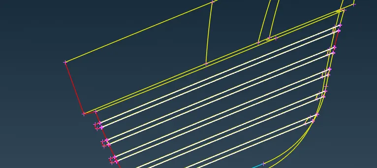
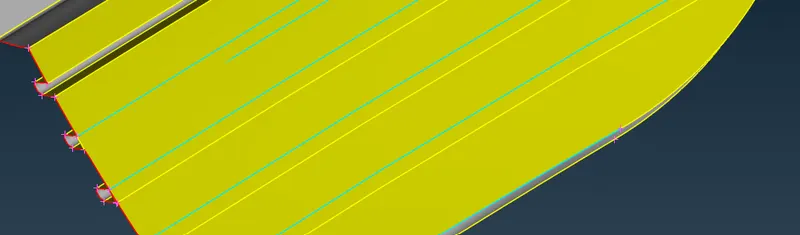
(d)Eliminating surfaces that are not connected by simply deleting selected surfaces:
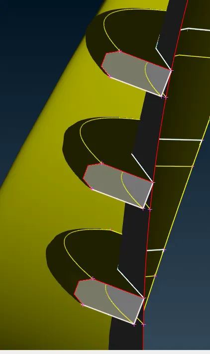
(e) remove the curved surfaces using Cons>project and fix the single cons
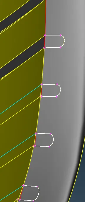
Small gaps was found in the cons that are connected using cut.
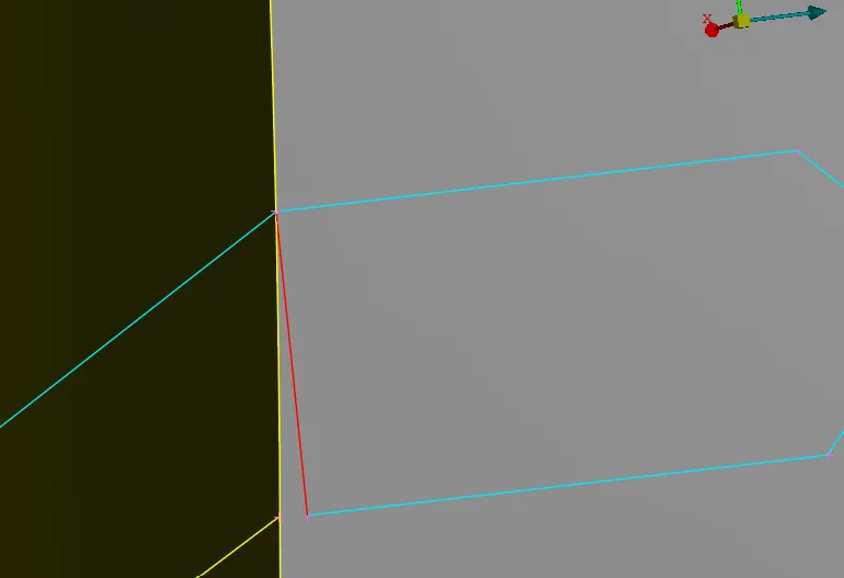
Repeating the same process for other similiar surfaces.
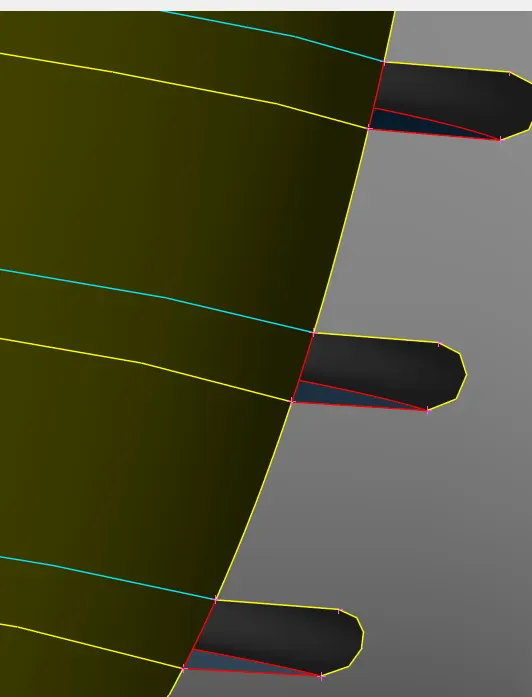
(f) Using New>Coons form new surfaces for all the fins
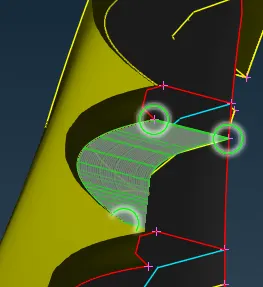
After applying new surfaces:
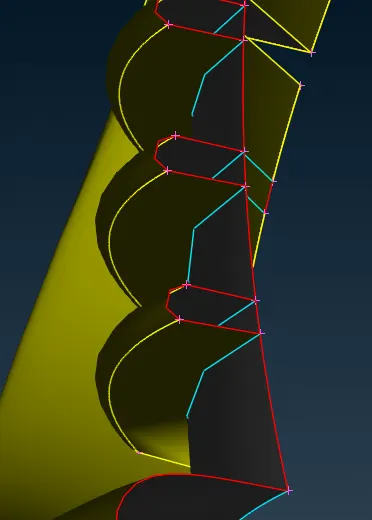
(g) Eliminating volumes using tools like delete tool.
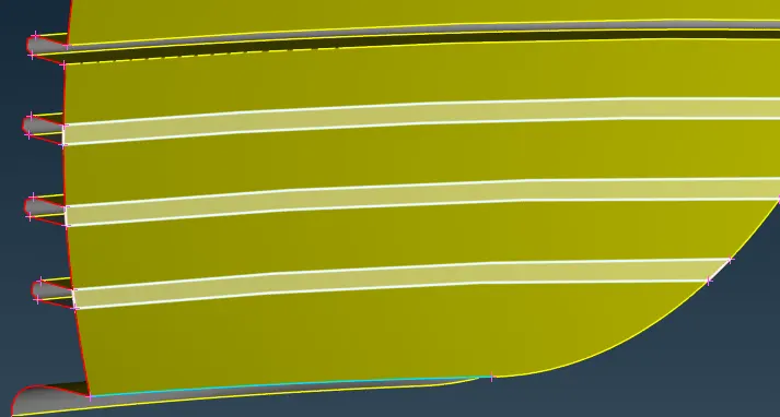
Final result:
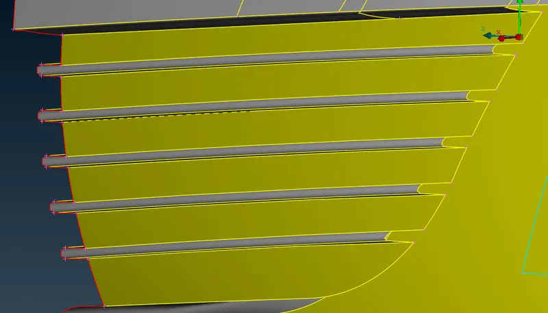
Working on Grilles-2's single cons, triple cons and extra surfaces :
Tools used to patch the surface: Delete, Cons>Paste,Cons>Project, Hot Points>Delete, Faces>cut, Faces>New
(a) Isolating Grilles-2
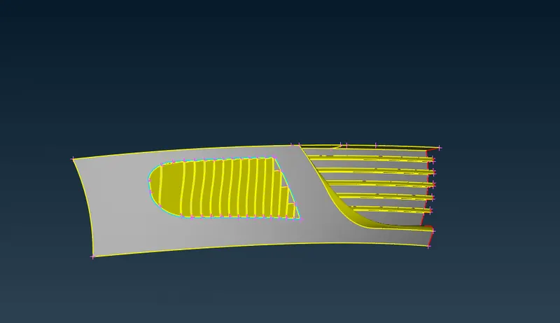
(b)Eliminating extra surfaces and unwanted volumes
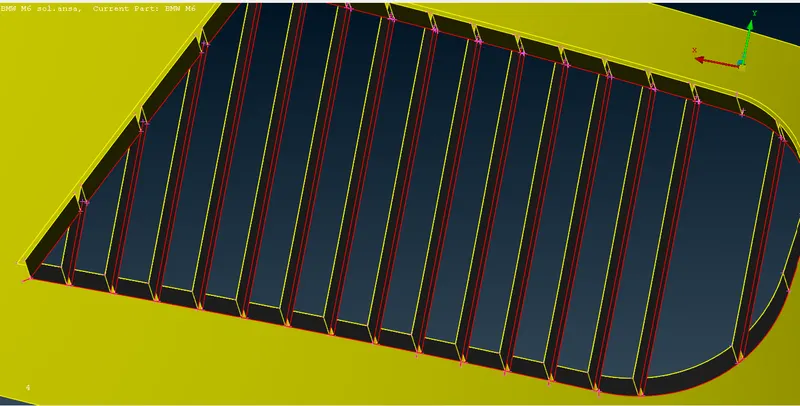
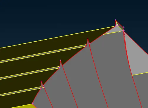
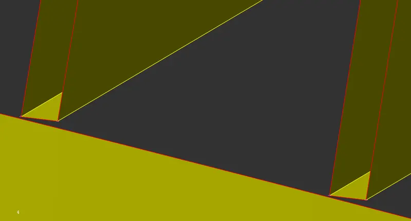
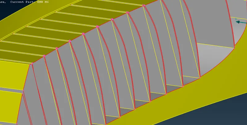
(c) Now we will use cut tool to eliminate surfaces present in the figures below
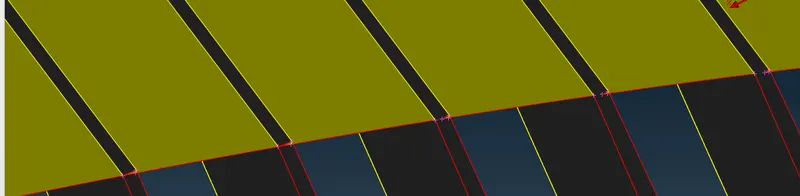
(d) Eliminating smaller surfaces using cut and delete tool:
(e) After cleaning surface and using new faces tools where required:
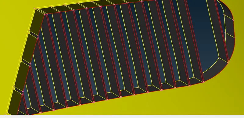
(f) With fill hole and New>Fitted tools, new surfaces are created
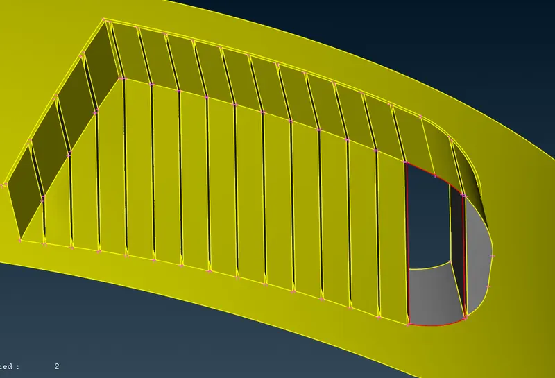
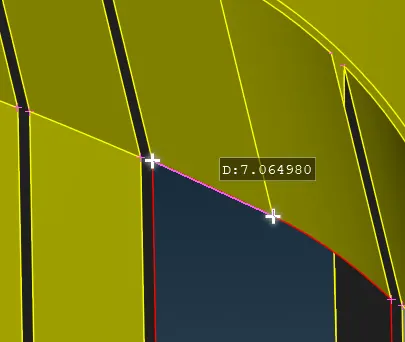
(g) Using measure tool, to find distance between the hot points and copy to the opposite con
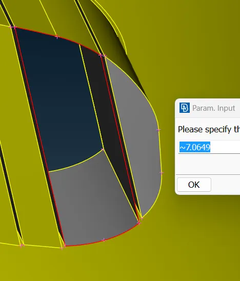
(h) Now filling the gap using New>Fitted tool and fixing the remaining last surface we get.
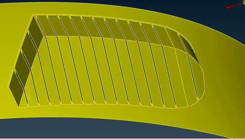
Inspecting grilles-3 by isolating the entity using !Not tool and lock tool:
(a)
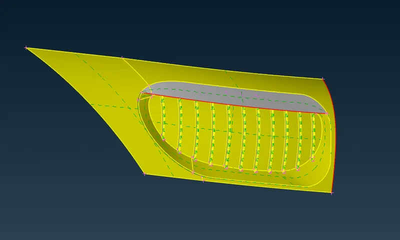
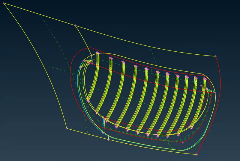
Lots of single cons are present and triple cons.
(b) Removing Triple cons by simply deleting extra surfaces forming volumes:
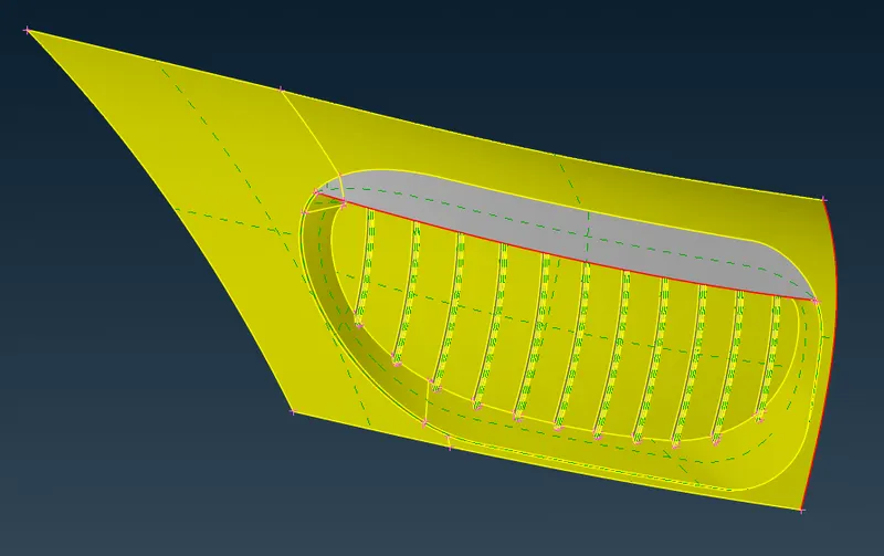
(c) Project the selected con on the grilles:
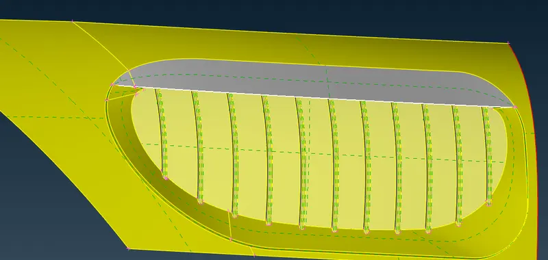
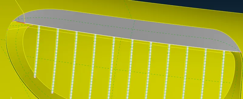
(d) Using Project cut tool to make perpendicular cuts on grilles fins:
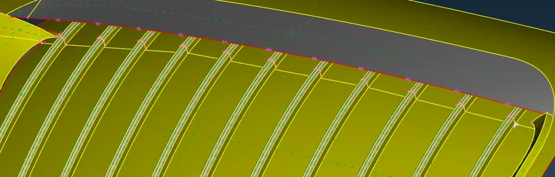
(e) Use extend tool to extend the selected cons to the surface:
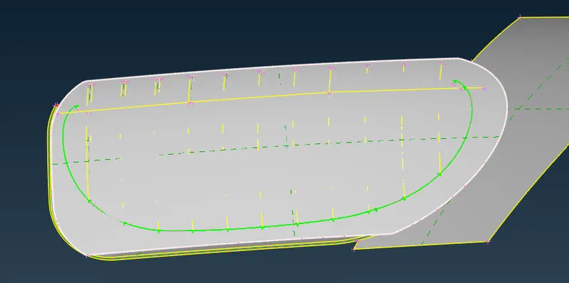
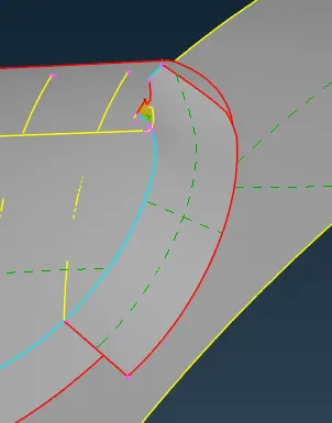
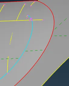
(f) Remove all the extra surfaces after intersect tool has been used using delete tool:
 =>
=> 
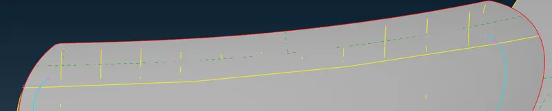
(g) Using cut tool:
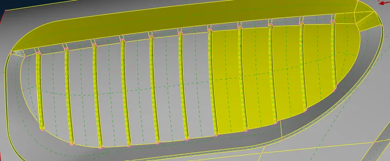
(h) Using faces>cut, Proj. cut, Hot Points>Project, Hot Points>Parametrical and Faces>New>Coons tools the Grilles-3 was completed
Working on car's feature shown below:
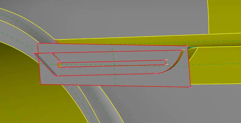
(a)Deleting the extra surfaces:
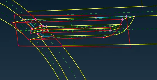
In this wireframe mode, it was observed that the surfaces are not in contact. Thus, using intersect tool.
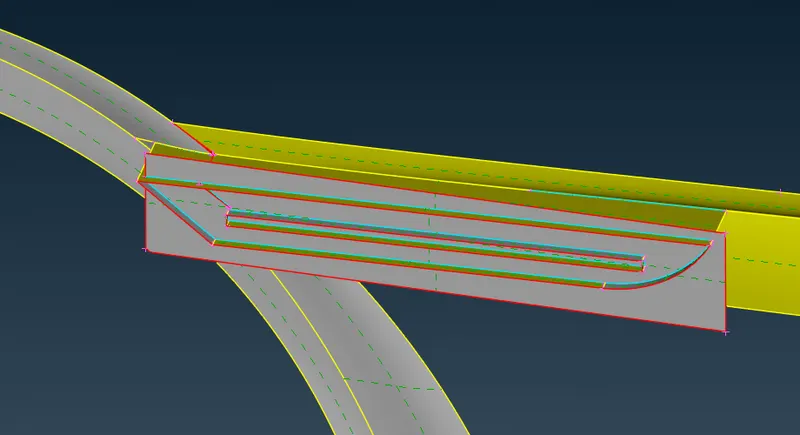
(b) Now, removing the extra surfaces producing triple cons with the help of delete tool and connecting the cons that are needed to be connected using cut tool and deleting the unwanted surfaces.
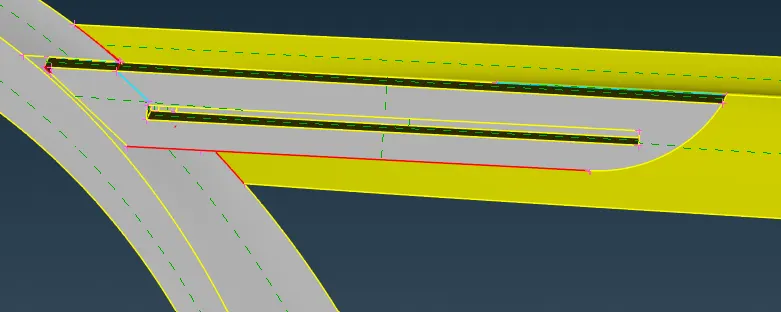
(c) Fill hole tool is used to fill the gap in the surface.
Eliminating triple con and volume by using extend and cut tools on the following surface below:
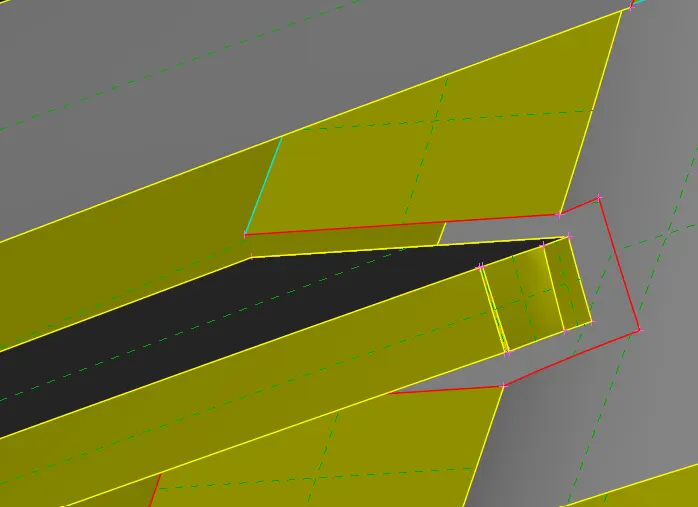
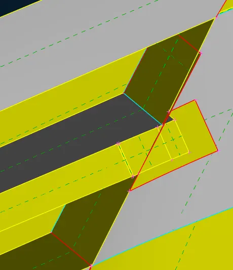
(d) Removing the extra surface using cut and delete tool:
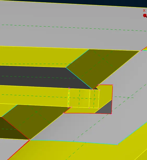
(e) Using Extend, cut, delete, paste, new>Fitted/Coons and fill hole tools the irregularites were removed.
Eliminating unecessary volumes:
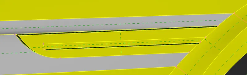
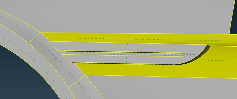
Fixing Rear View Mirror and nearby surfaces:
(a) Fixing the two single cons present using cut-delete-New>Coons tool
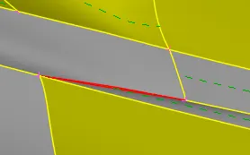
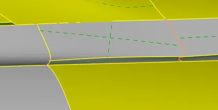
(b) Removing the triple cons from the inside of car near the rear view mirror by deleting associated surfaces.
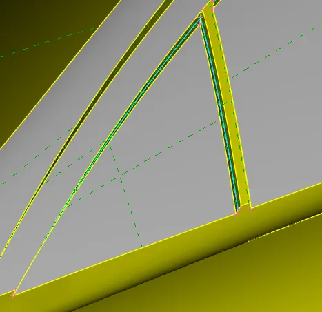
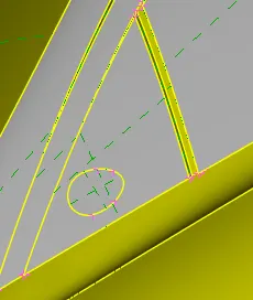
(c) Isolating the rear view mirror using !Not tool:
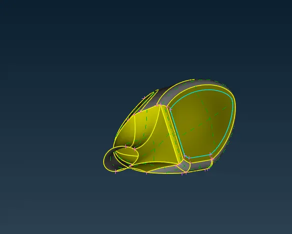
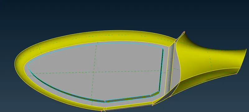
(d) deleting surfaces to eleminate triple cons.
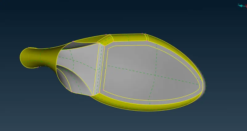
(e) Now connecting the volume of the side rear view mirror to car volume by deleting the common surface of the side mirror and surface.
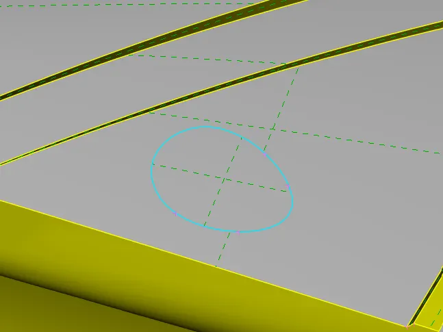
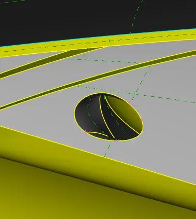
Fixing Front wheel
(a) Isolate the wheel:
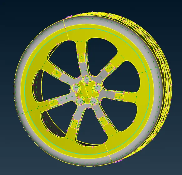
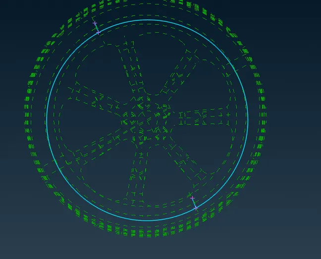
As per the above wireframe mode, 3 triple cons are present.
(b) Hide the top surface of Tyre using not tool:
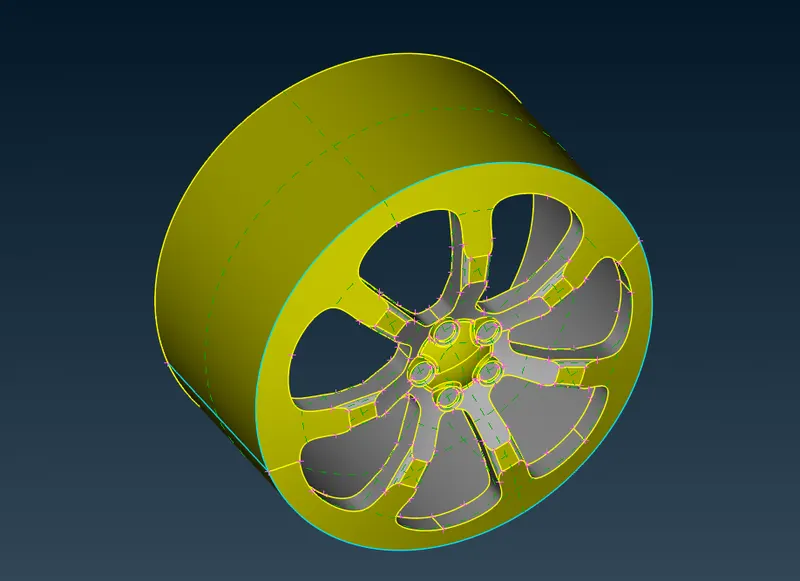
(c) Delete the surfaces to eliminate the volumes:
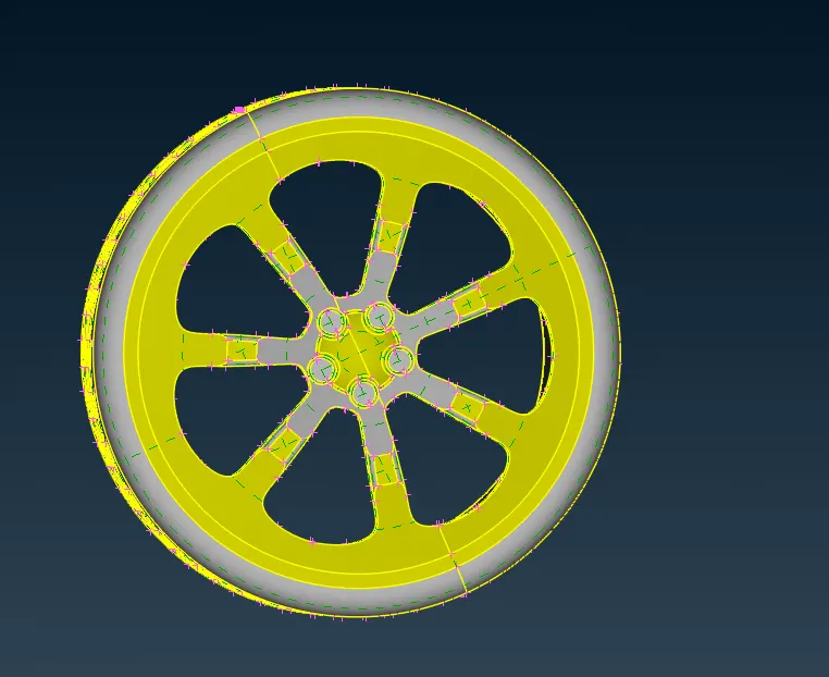
(d) Two red cons are present at the back of the wheel, that is rectified using delete and New>Coons tool:
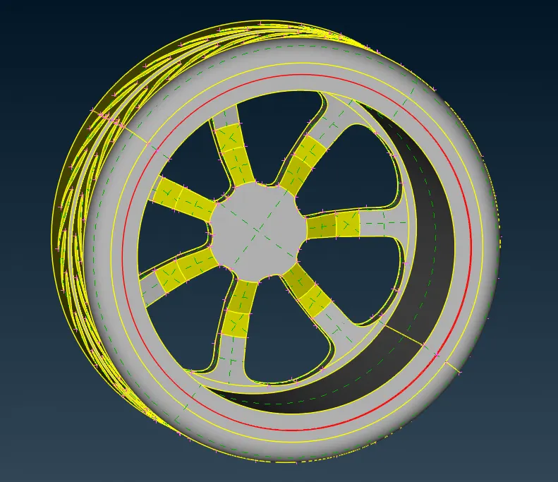
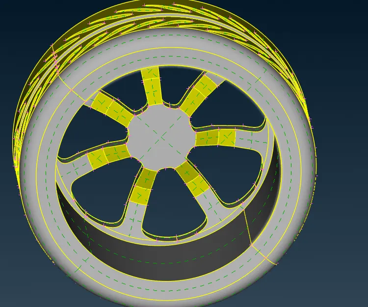
Fixing rear wheel:
(a) Isolate the rear wheel
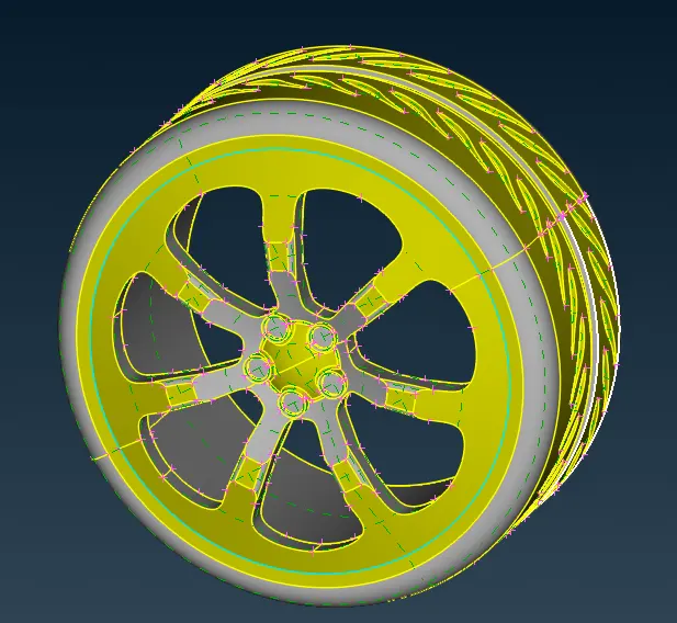
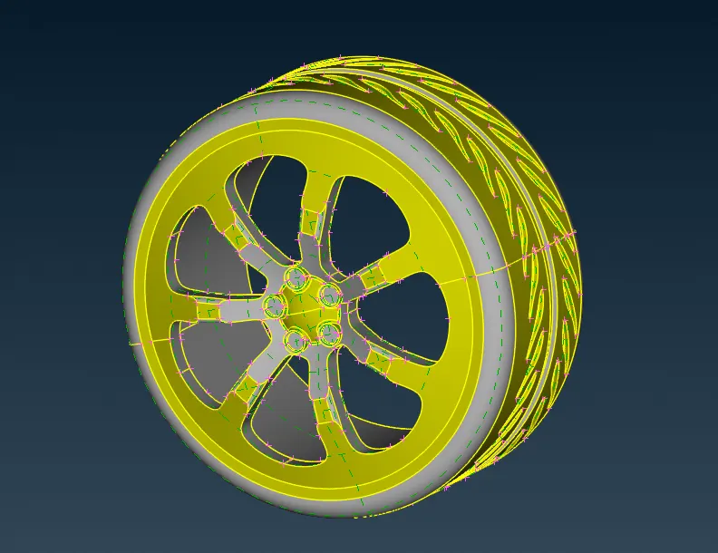
(b) As the rear wheel has same issuses as the front wheel had, after using same steps to remove all irregularities:
Now removing the triple cons from the rear part of the car:
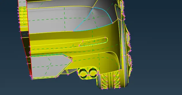
(a) Removing the extra surface from the back using delete tool:
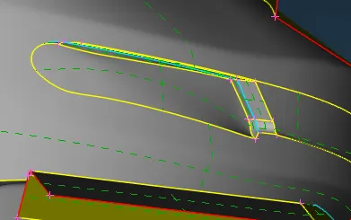
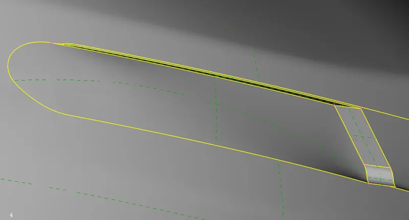
(b) Removing extra surfaces and triple cons from the number plate area and associated surface:
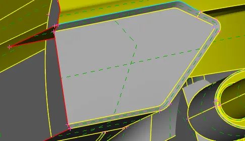
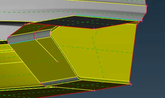
Using delete tool and New>Coons tool and use Topo tool:
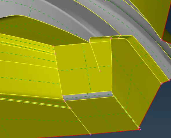
(c) Fixing Tail light:
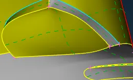
Remove extra surfaces to eliminate volume:
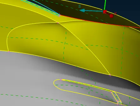
Removing the extra surfaces and removing triple cons and single cons from lower chasis of the car body:
(a) Removing unnecessary surfaces using Faces>Intersect, Extend, cut and Delete tools, Cons2Curve and use New>Coons to create new surface where required:
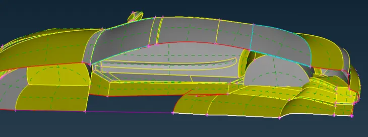
(b)After using all the tools the car floor was created:
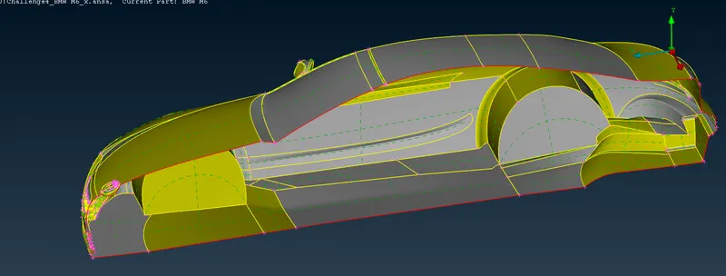
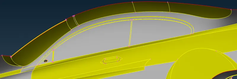
Fixing the windshields and :
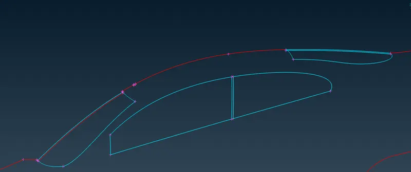
(a)Using delete tool, removing all the volumes forming triple cons:
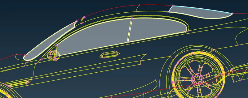
(b) After deleting all selected surfaces, all triple cons and volumes were eliminated
Working on the logo:
(a) Isolate the logo using !Not tool in lock mode:
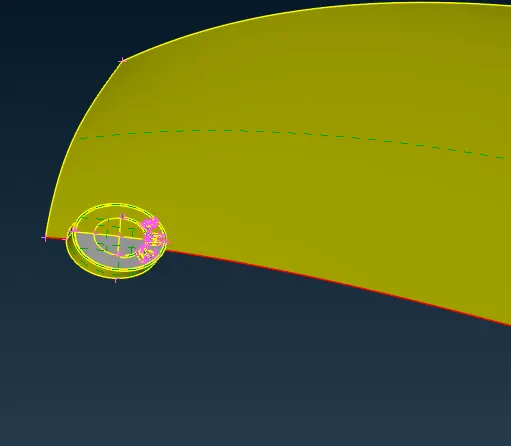
(b)Use Not tool to hide the hood:
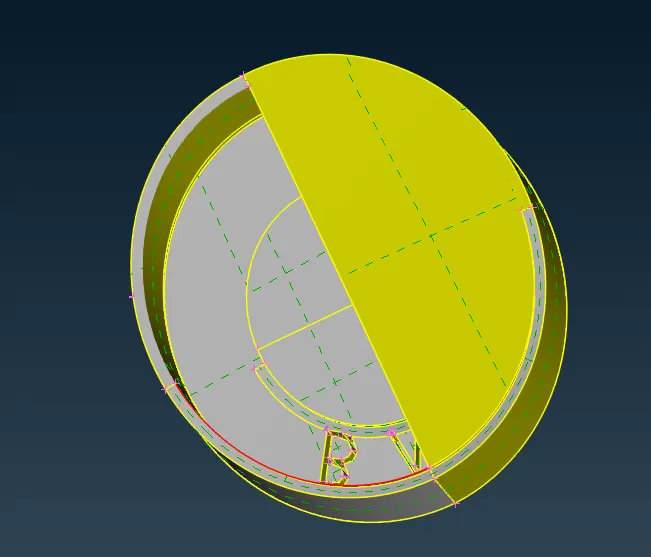
(c) Remove all the entities that will produce a volume using delete tool:
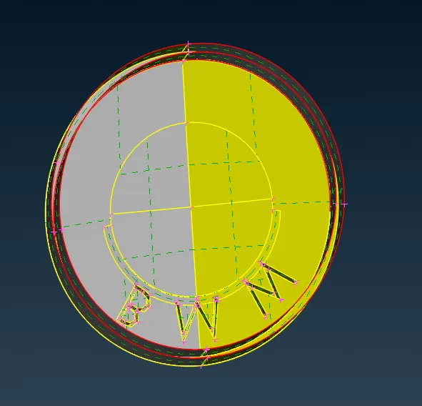
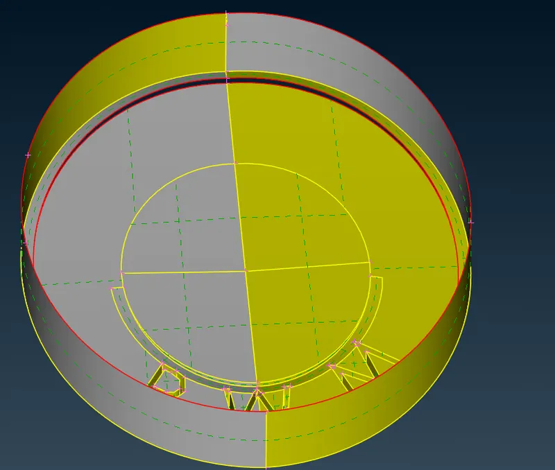
(d) Patch the face of the logo using New>Coons
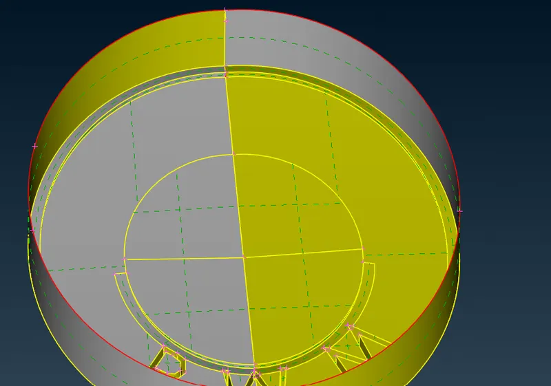
(e) Remove unnecessary hot point and using extend connect the logo and the hood surface
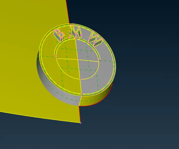
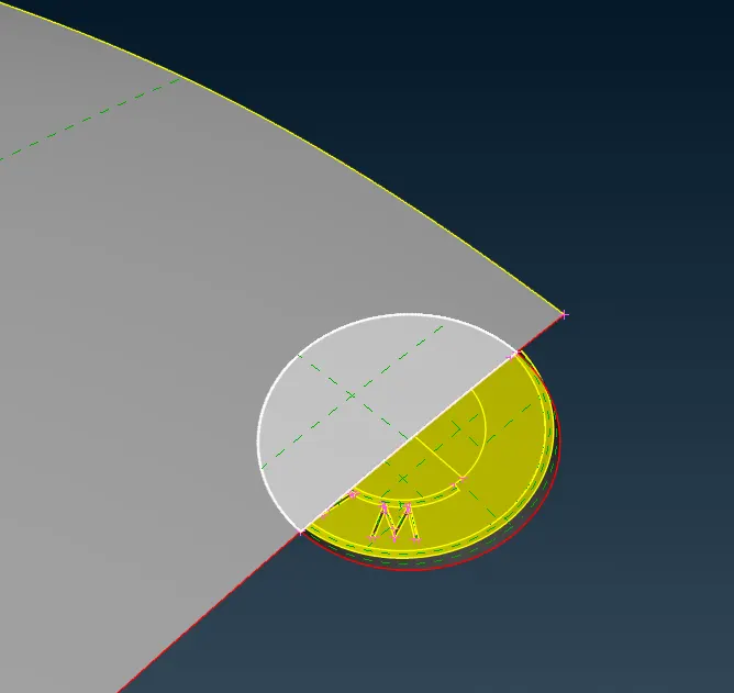
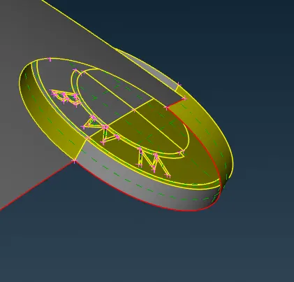
(g) Using Delete tool remove the entity creating triple con with logo:
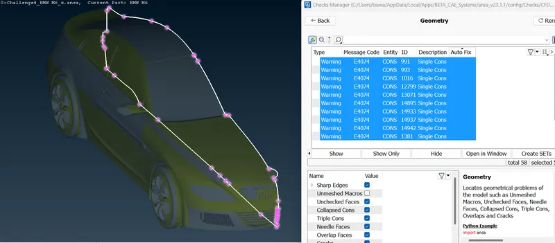
Checking for toplogical errors in geometry:
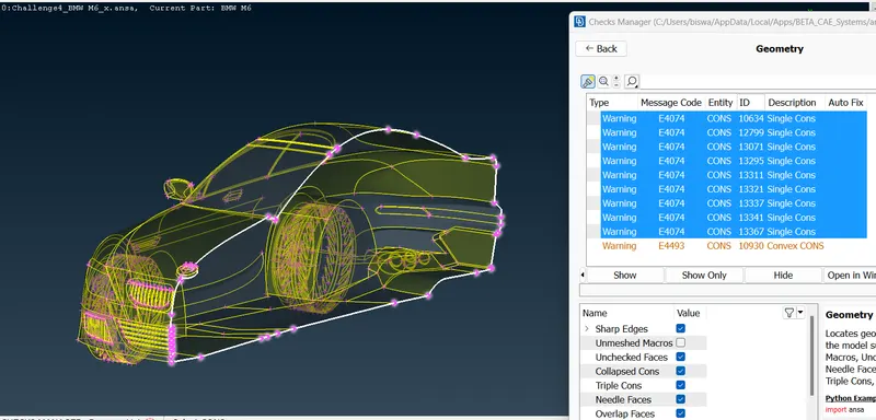
All the single cons found are desired single cons.
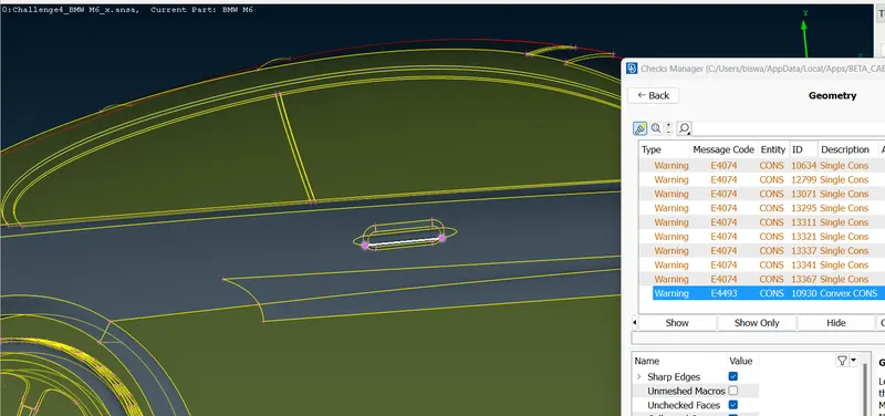
Now resolving Convex con error:
Using cut tool and New>Coons tool the error was eliminated:
Using Orient tool to properly align all the surfaces:
PID NAMING:
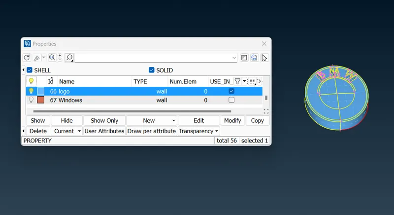
(a) Now isolate logo of the car using !Not tool and assign PID name as logo
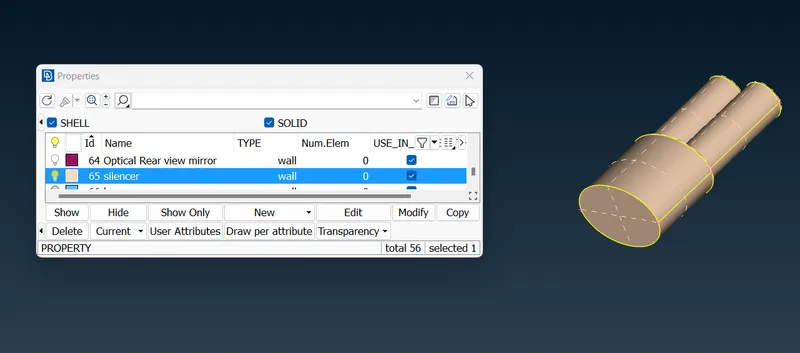
(b) Now isolate silencer of the car using !Not tool and assign PID name as Silencer.
(c) Similarly assign PID names to the car lights:
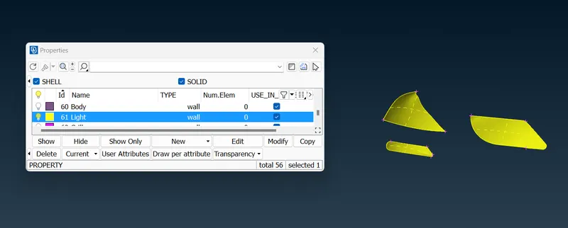
(d) Grilles are assigned:
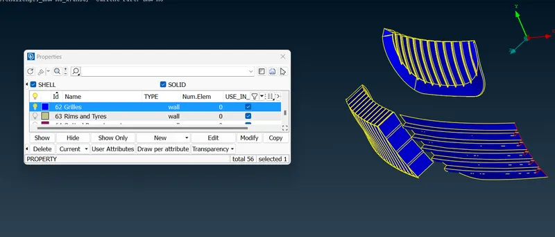
(e) Now isolate rear-view mirror of the car using !Not tool and assign PID name as Optical rear-view mirror.
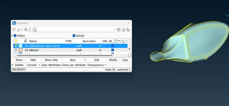
(f) Assigning Windows:
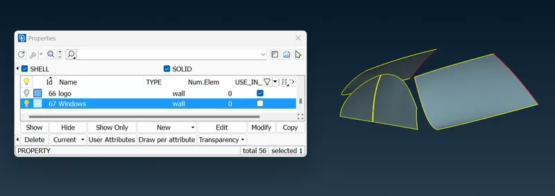
(g) Rims and Tyres:
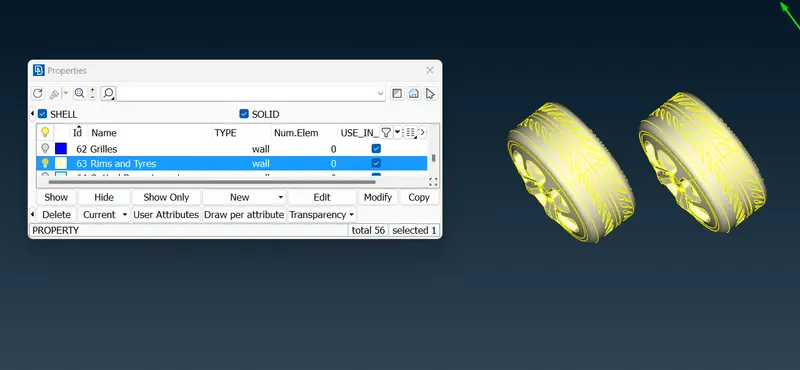
(f) Now deselect all the assigned with PIDs to isolate the car body using PID manager and assign it as Body.
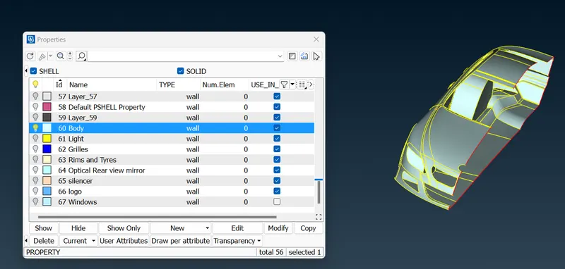
(g) Now checking if anything is unassigned, select all the PIDs that were present earlier and view using fit in tool.
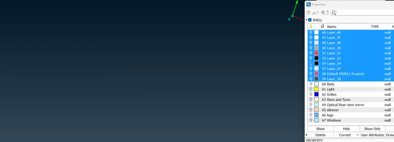
Thus, no element is missing.
(h) Using compress tool, all the unassigned PIDs are removed.
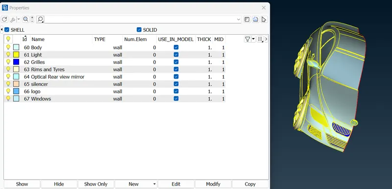
INSPECTING MODEL TO PREVENT MESH FAILURE:
(a) As minimum length will be given 1mm for car body, removing the cons that are closer to each other having gap of less than 1 mm.
Use cut tool:
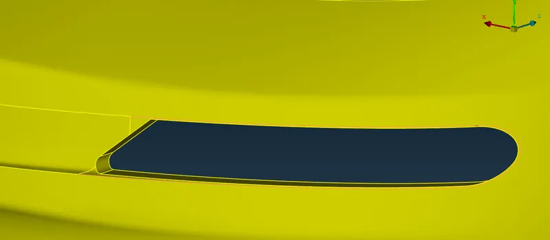
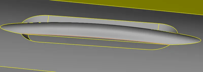
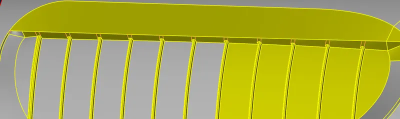
Finding the minimum lengths of the PIDs using measument tool on smaller surface of that PID to check if the mesh length given is compatible or not:
For lights:
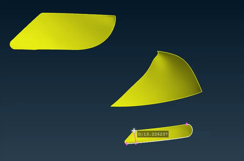
As its 13.22mm > 4mm, thus there will be no issue during surface meshing at 4mm.
For Grilles:
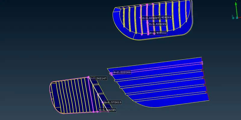
Here minimum is 0.4 mm
Tyres:
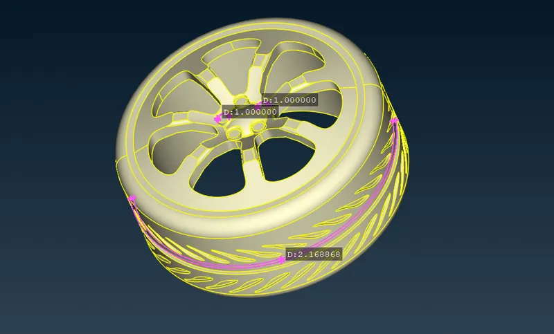
Here minimum length is 1mm.
But some edges are closer to each other, using cut tool to eliminated non-significant curves.
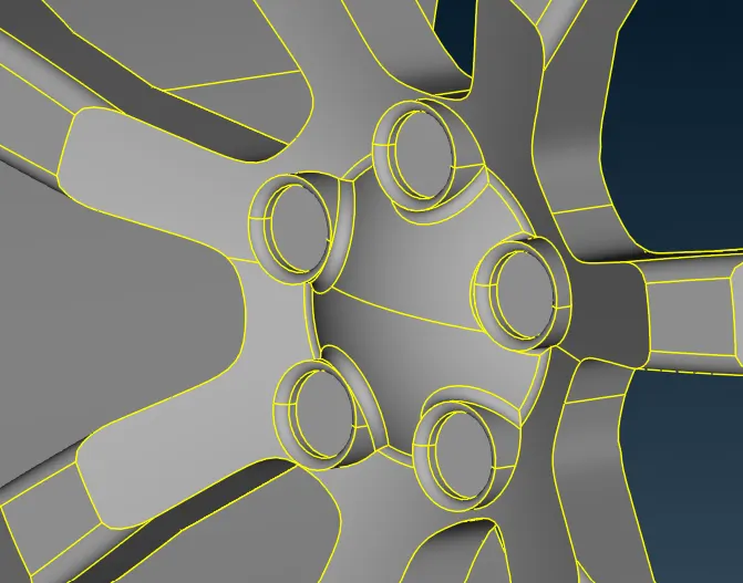
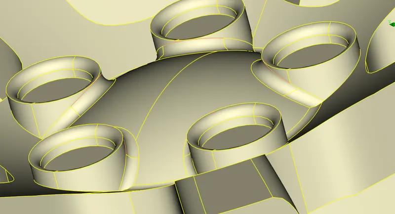
These surfaces are having cons very near to each other. Cut tool is used to remove some of the cons to avoid mesh errors.
For Optical rear view mirror:
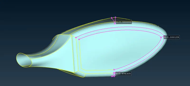
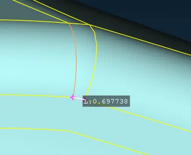
Windows:
As windows have larger surface, thus no need to check.
Silencer:
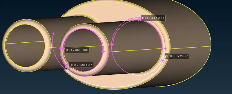
As the silencer is having minimum length of 0.85 mm< 1mm, topo cleanup is done by removing the cons using cut tool.

For Logo:
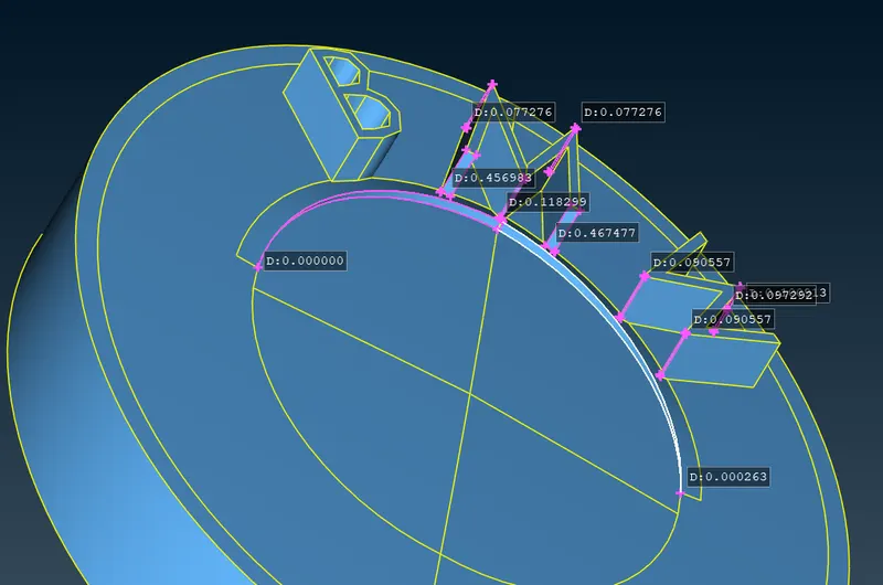
As there is a sharp edge, Removing the smaller width areas to avoid mesh failures:deleting the surface and create a new surface using COONS tool.
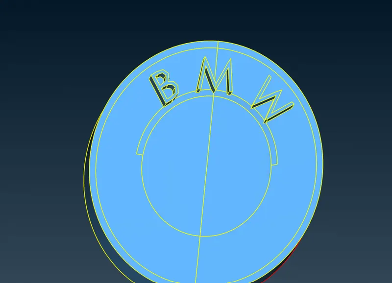
As all the geometrical errors were resolved, proceeding to surface mesh:
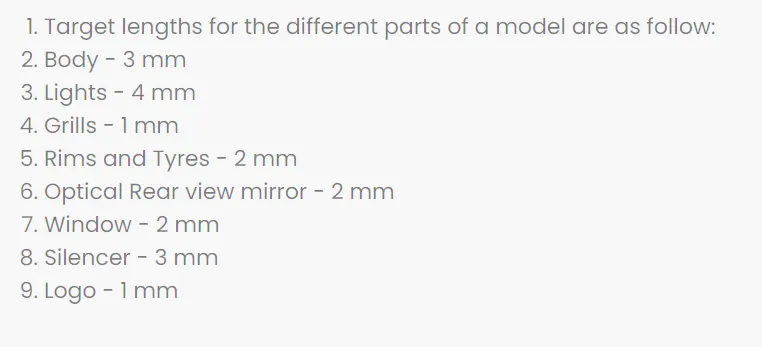
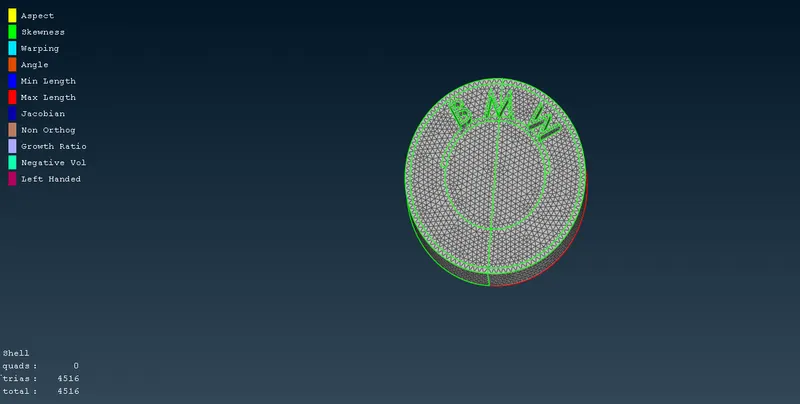
1. LOGO:
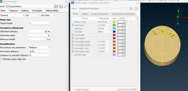
setting Mesh> Perimeters> Length>Perimeters and Macros value = 1mm
Now meshing the logo using Spot Mesh algorithm and doing Shell mesh re-construct in Hidden mode.
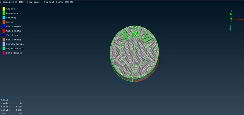
36 off elements were found, fixing the error in topo mode:
2. Grilles
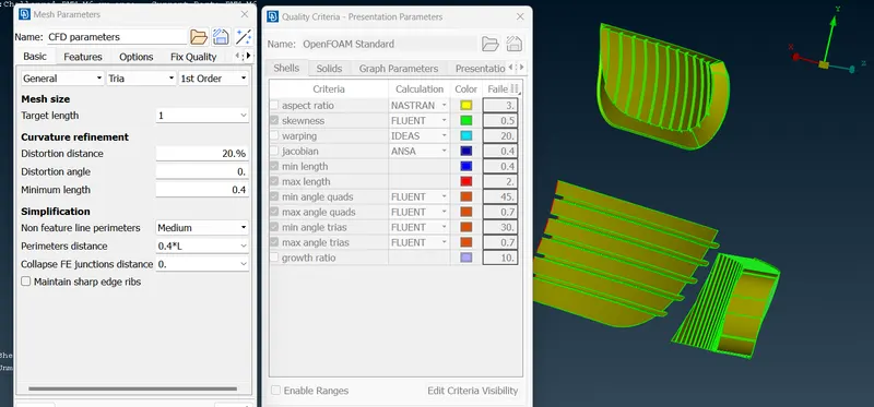
setting Mesh> Perimeters> Length>Perimeters and Macros value = 1mm
Now meshing the grilles using spot Mesh algorithm.
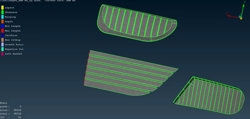
Using Shell mesh>re-construct in Hidden moe and removing the errors manually .
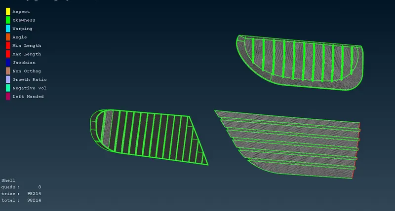
3. Windows:
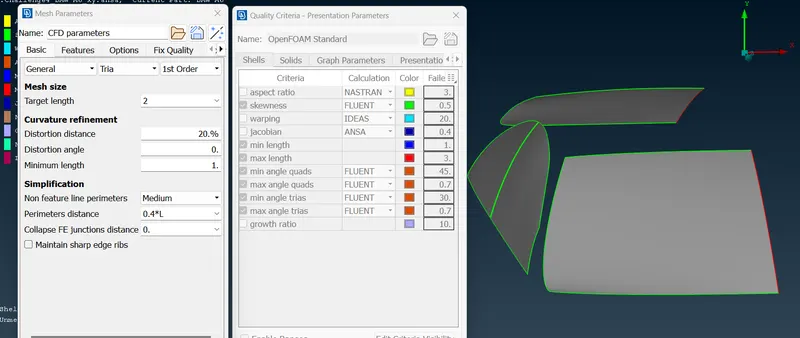
setting Mesh> Perimeters> Length>Perimeters and Macros value = 2 mm
Now meshing the windows using Spot Mesh algorithm.
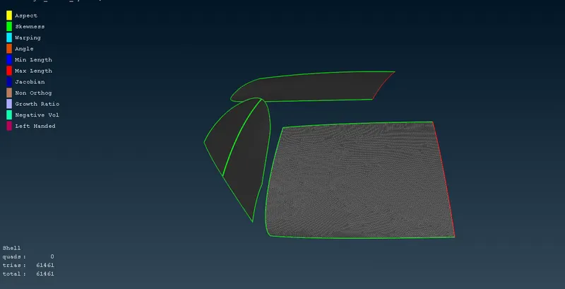
No off elements found.
4. Lights:
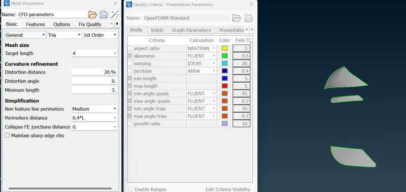
setting Mesh> Perimeters> Length>Perimeters and Macros value = 4 mm
Now meshing the lights using spot Mesh algorithm.
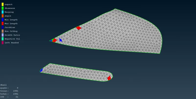
Using tools like Shell mesh >Reconstruct and Smooth, Grid>Move>surface, off elements were eliminated.
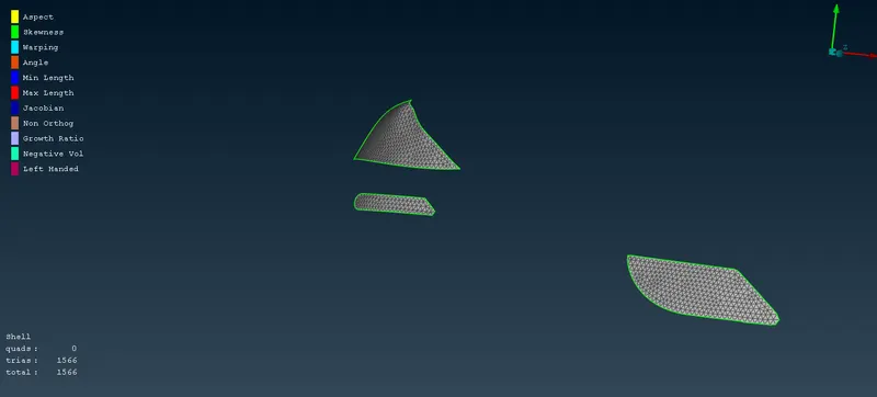
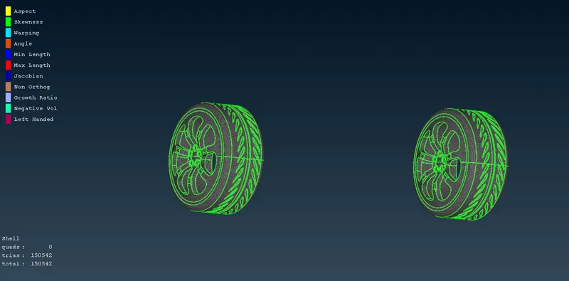
5. Rims and Tyres:
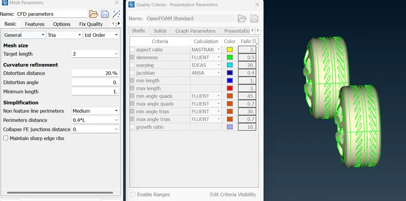
setting Mesh> Perimeters> Length>Perimeters and Macros value = 2 mm
Now meshing the wheels using Spot Mesh algorithm.
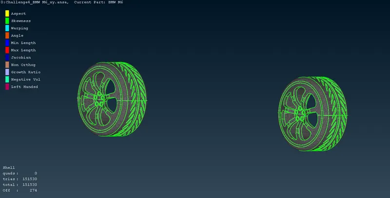
Both the wheels have 274 off elements.
Using Shell Mesh > Reconstruct:
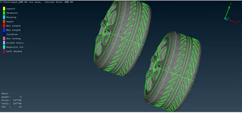
Off elements reduced to 10.
Resolving these off elements using Grids>Move tool:
6. Silencer:
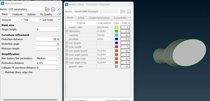
setting Mesh> Perimeters> Length>Perimeters and Macros value = 3 mm
Now meshing the silencer using Spot Mesh algorithm.
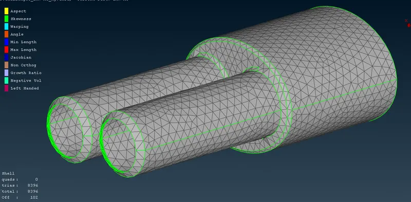
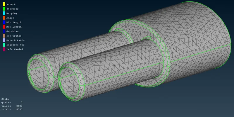
As there are off elements, using Shell Mesh>Reconstruct
7. Optical rear view mirror:
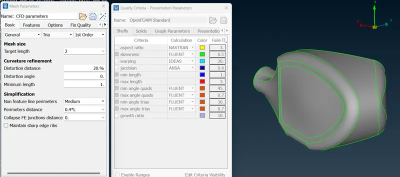
setting Mesh> Perimeters> Length>Perimeters and Macros value = 2 mm
Now meshing the Optical rear view mirror using Spot Mesh algorithm.
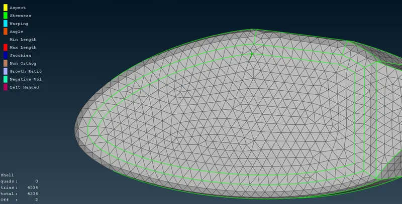
2 off elements present due to skewness.
using Shell Mesh>Reconstruct
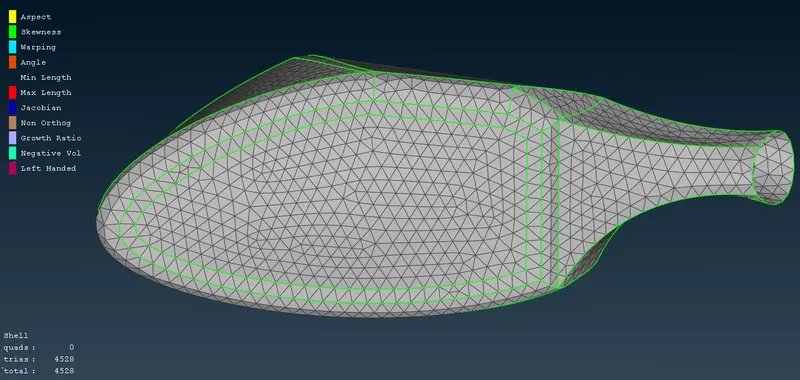
8. Body:
As there are associated meshed entities with the car body, the monimum length is to be taken as 0.4 mm .
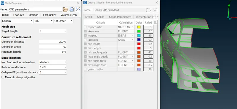
Deselected the perimeters which are in contact of other PIDs to prevent the mesh erasure and set perimeter length=3mm
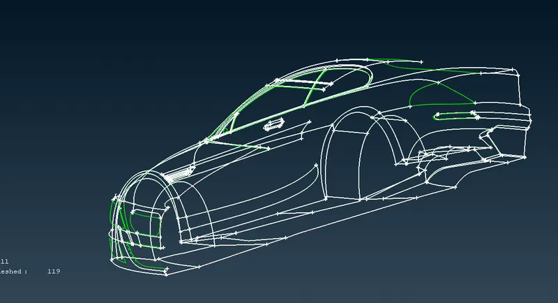
Spot Meshing done on the body:
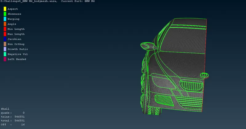
Off elements are present, reconstruct tool is used:
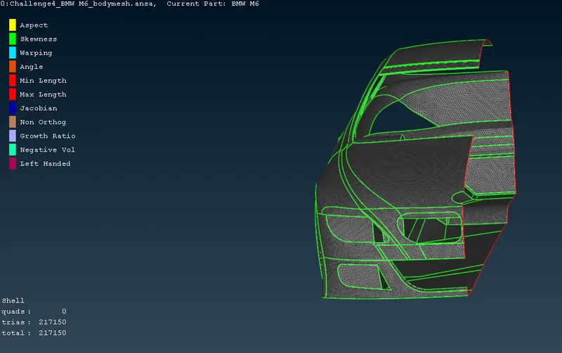
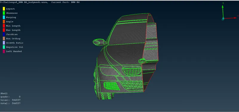
COMPLETING THE CAR MODEL:
Set the car in top view mode, hiding the logo and using the transform>copy tool after selecting the symmetrical half of car.
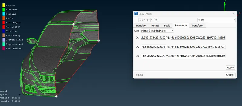

Using paste tool in TOPO mode to paste the single cons together.
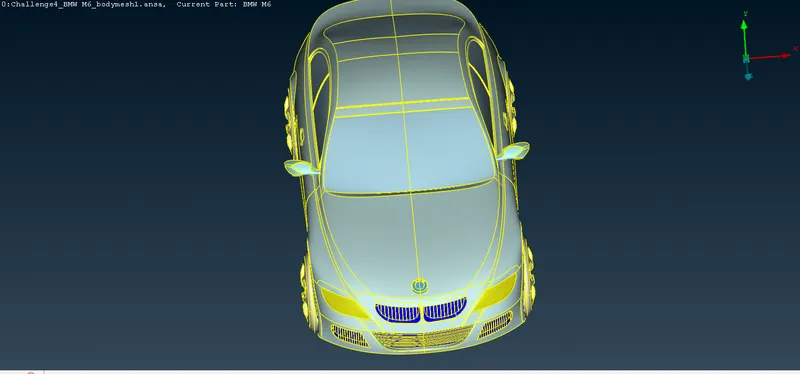
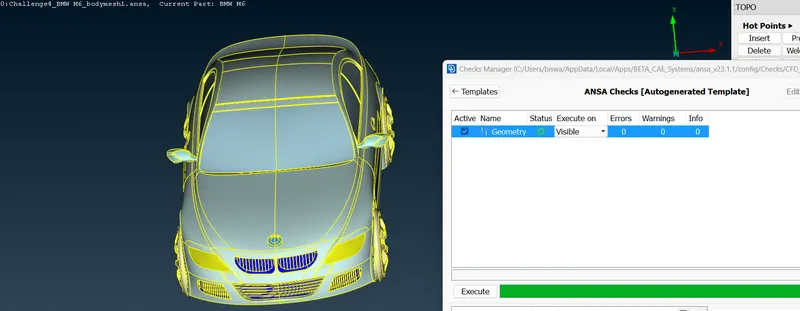
Checking for topo errors :
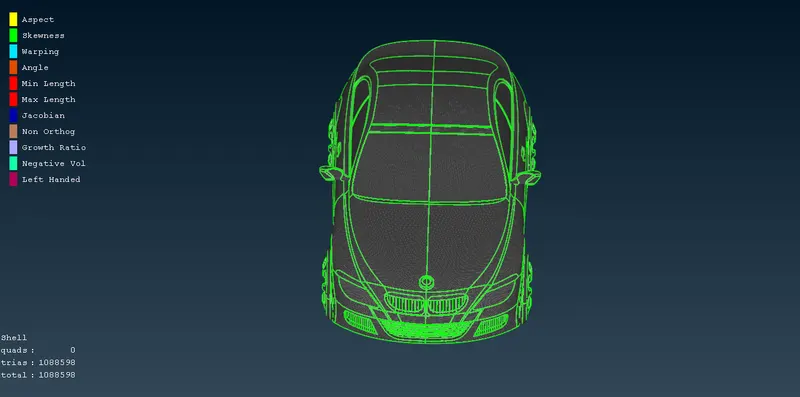
Final mesh after meshing unmeshed surface:
Measuring the length of the car:
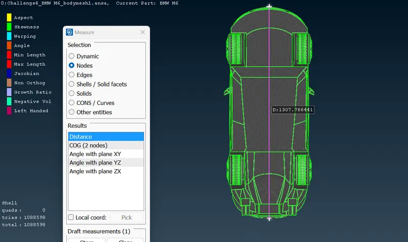
L=1308 mm (Approx.)
Wind Tunnel Dimension:
- The distance of the wind tunnel's front face from the front of the car should be 4L and wind tunnel's rear face from rear it is 6L.
- Bottom face of the wind tunnel is taken near the wheels as we need cfd results for the top surface of car.
- The top face of wind tunnel is at 3L distance from roof of CAR.
- The width is assigned as L distanace on each side from the car sides.
Creating wind tunnel:
- Create a point near the rims and tires using Points>Relative tool from one end of car bottom.
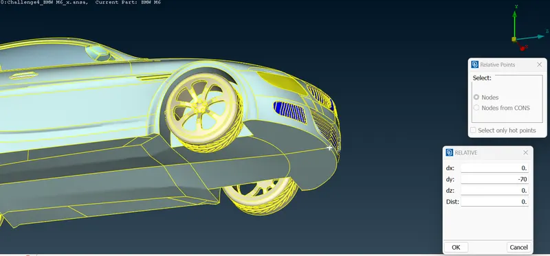
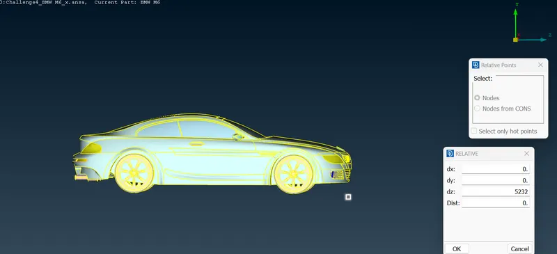
- Take the above point as reference and create another point in +ve x-axis at 4L=4*1308=5232 mm.
- Measure the dimensions from the refrence point of the car to rear of the car:
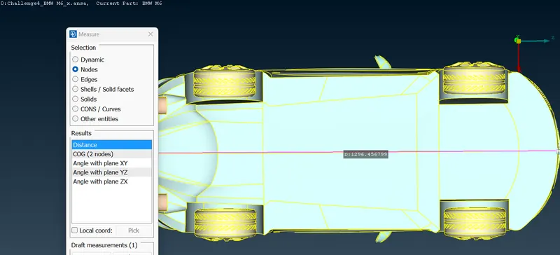
X=1296.5 mm
- Take another point behind the trunk using refrence point at 6L+X=6*1308+1296.5=9144.5 mm
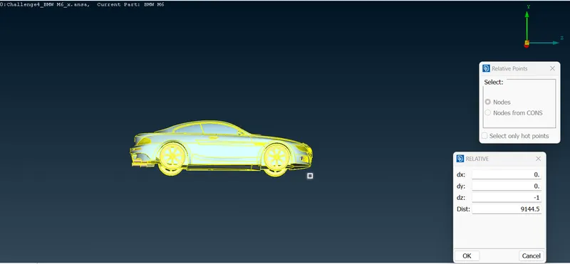
- Using the refrence points far from the rear and front of the car, create points for the width of the wind tunnel at L=1308 mm on each side.
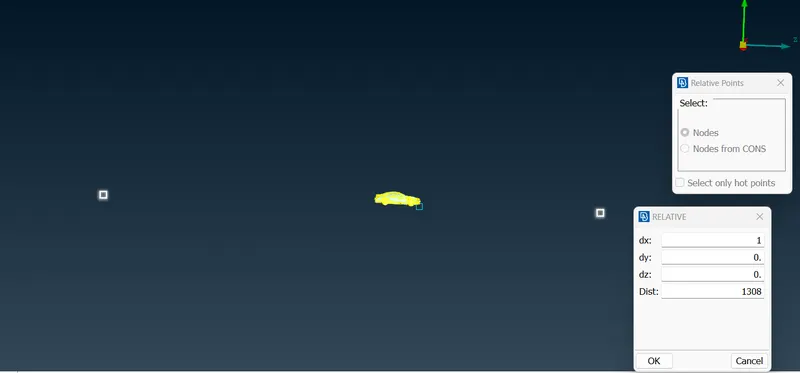
+
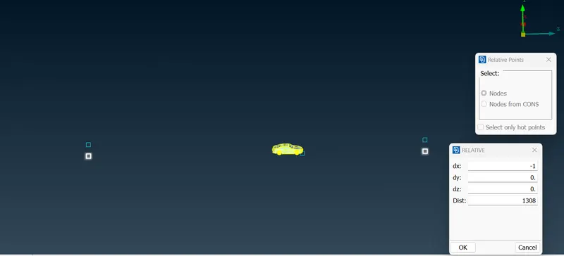
=

- Now use curve option to create a outline using the created points and then create a surface by using Faces>New>fitted tool:
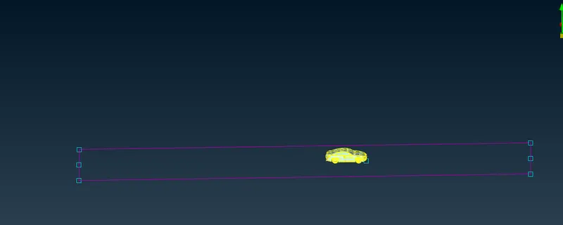
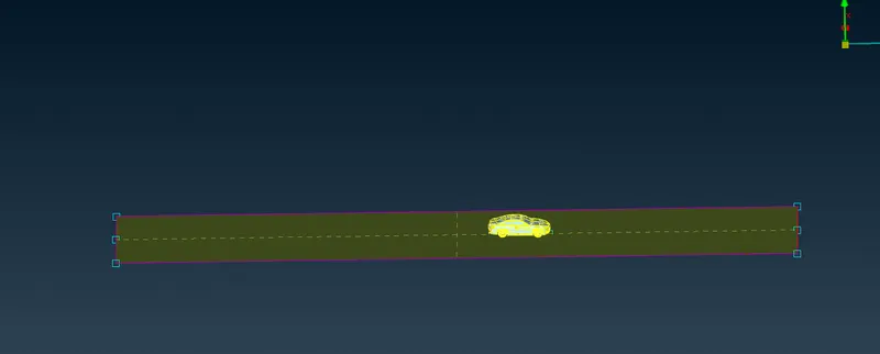
Assign new PID for the surface.
- Measure the vertical height from the car roof to created bottom surface of the wind tunnel.
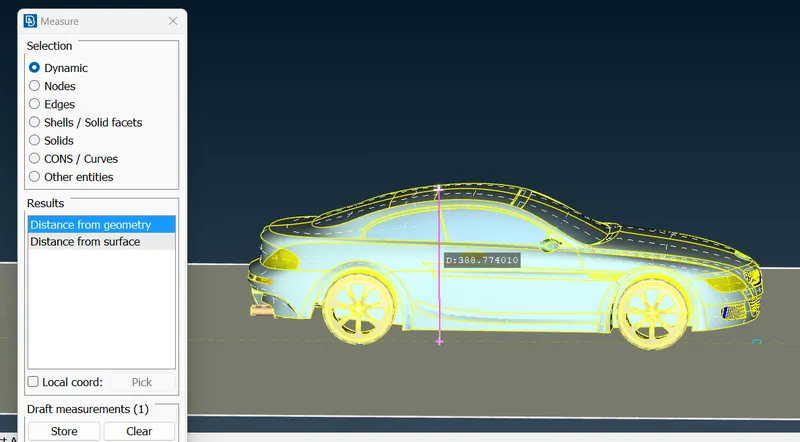
Y=389 mm (approx.)
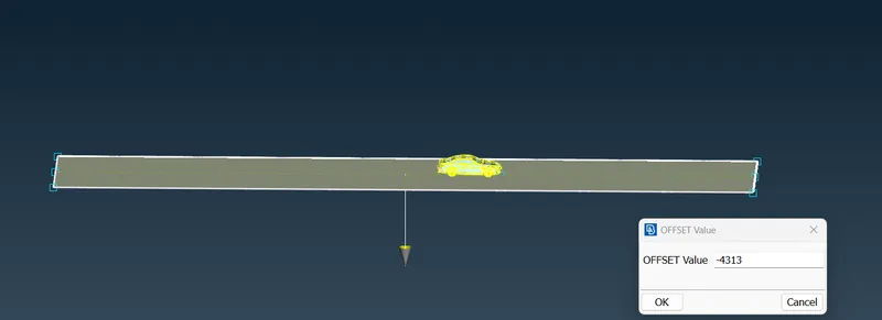
- Use Faces>Offset>face tool to create top surface of wind tunnel at 3L+Y= 3*1308+389=4313 mm.
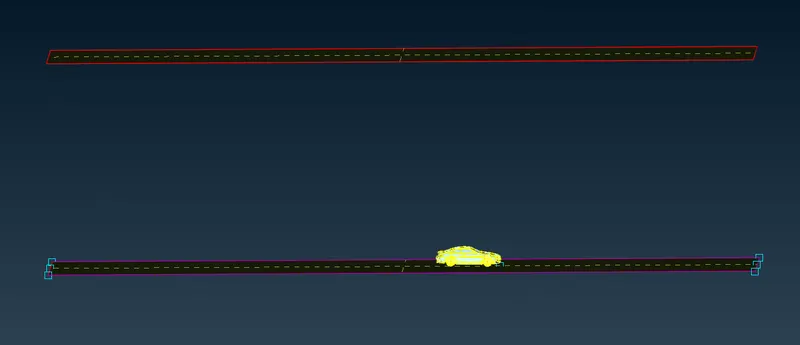
- Delete all the hot points and curves created to make bottom surface using delete tool:
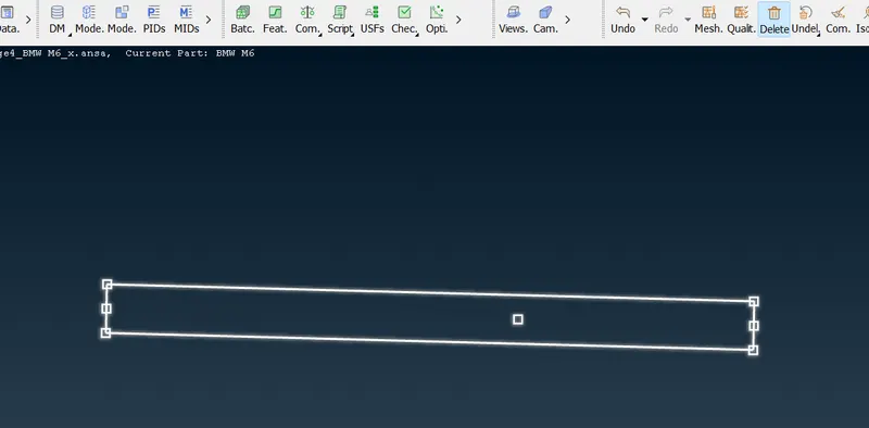
- Now using Faces>New>Coons tool to create remaining surfaces of wind tunnel and assign PID names for each surface.
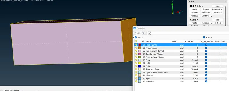
MESHING THE WIND TUNNEL:
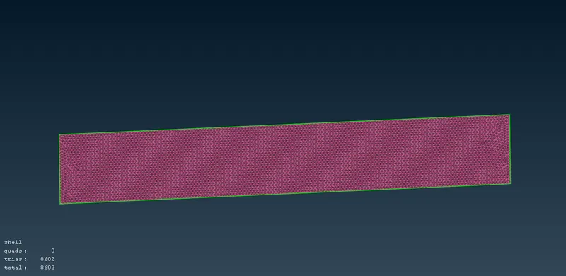
- The top surface is to be meshed with perimeter set to 100 and macros value as 100.
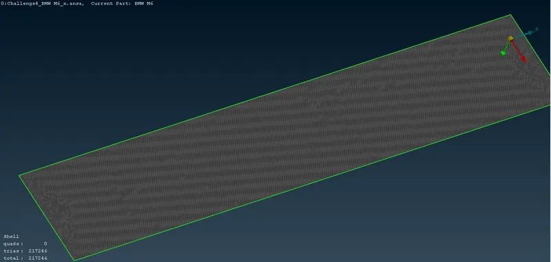
- Bottom surface is meshed with perimeter and macros values set to 20 as it is going to provide cfd data.
- As the mesh length is varying from bottom to top surface from 20 mm to 100 mm, Mesh>Perimeter>Spacing>Geometric tool is used with Dstart=20 and Dlimit=100 with factor of 1.1.
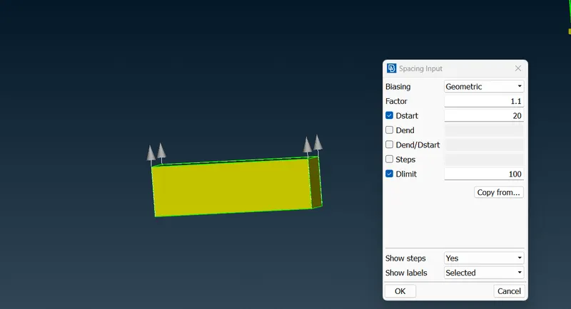
- Meshing bottom surface:
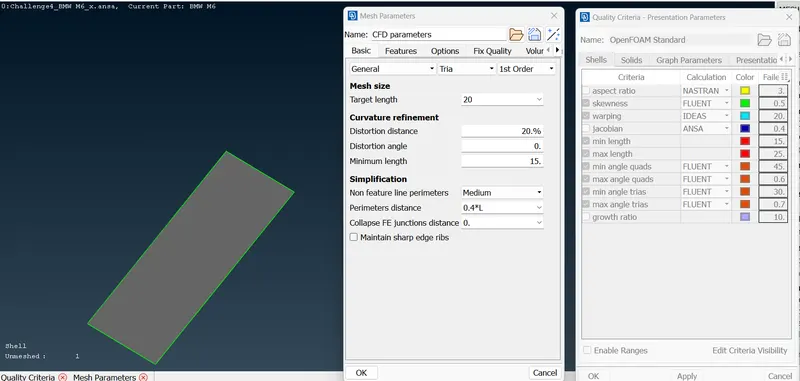
Meshed bottom surface:
- Meshing Top surface:
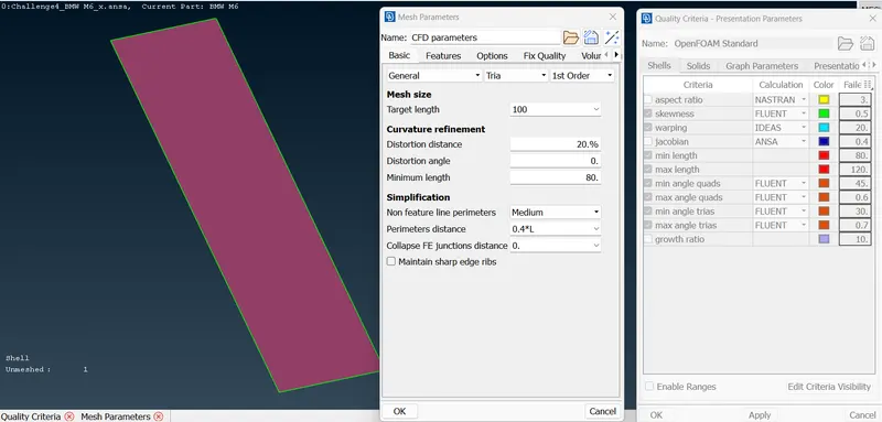
Meshed top surface:
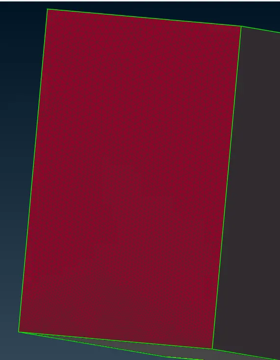
Meshing front and rear surface:
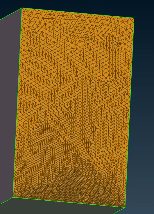
Using spot mesh tool mesh the remaining side surfaces:
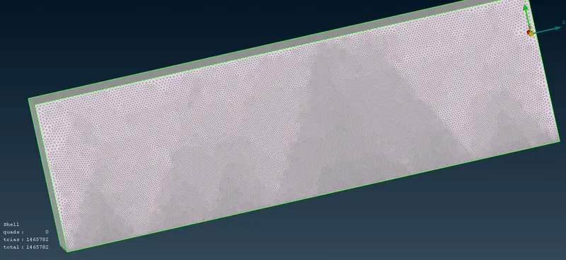
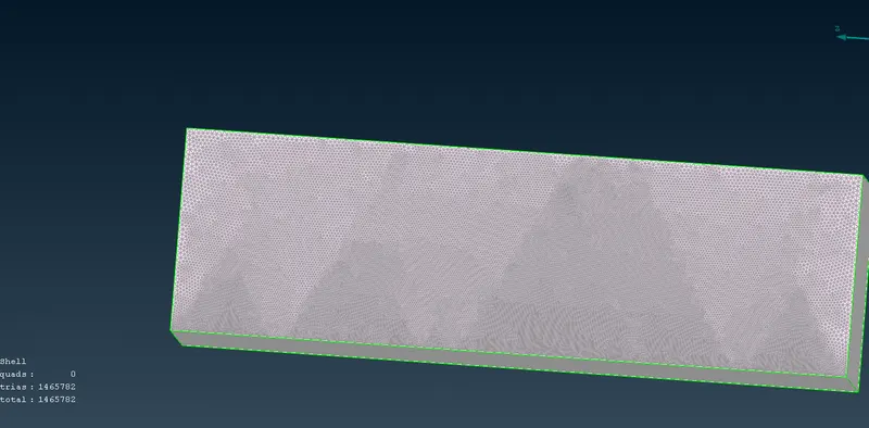
Final mesh:
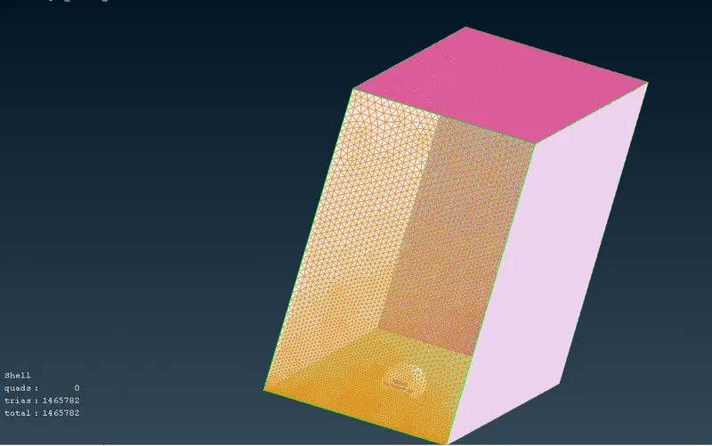
VOLUMETRIC MESH:
- Different volumes detected using Volume>define tool:
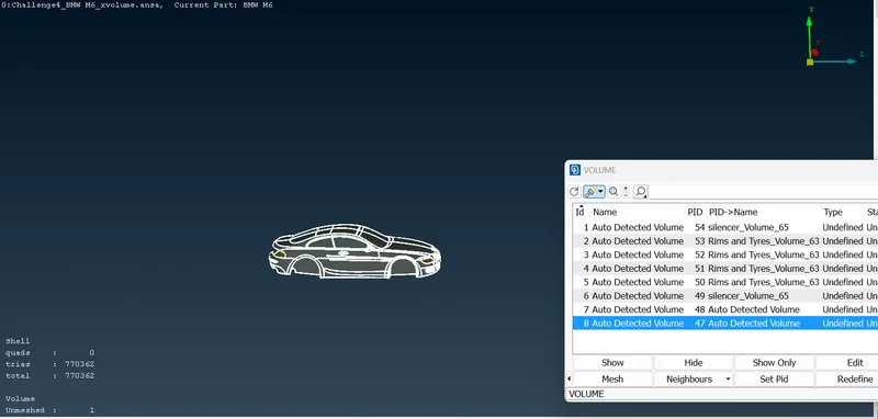
- Delecting the unnecessary volumes:
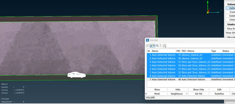
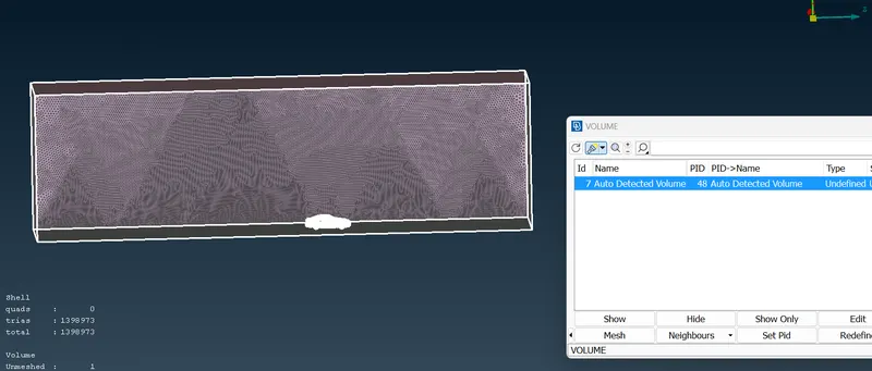
- The single volume present:
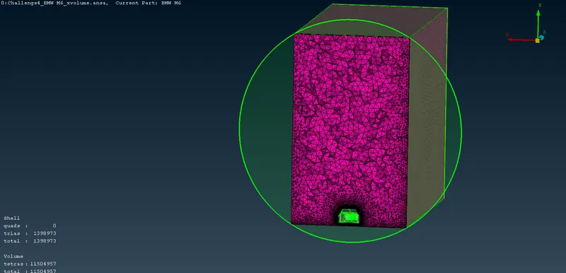
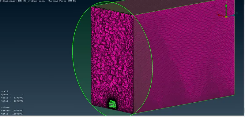
- Mesh the whole selection in V.Mesh mode.
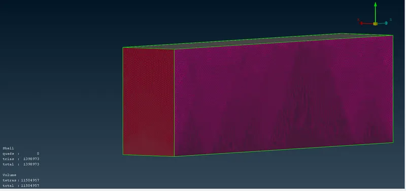
- Use cut XY plane to view the tetra mesh.
-----------------------------------------------------------------------------------------------------------------------------
- Less is the target length value smaller are the tria elements.
- Different PIDs or surfaces having different target length and quality length can cause in increase of off elements or removal of mesh. Thus, isolating surfaces connected to each other having different mesh length is necessary.
- Single volumes are generated for cfd by removing unnecessary surfaces, single cons and eliminating some volumes.
- More the number of elements, more time is taken for volumetric mesh.
-----------------------------------------------------------------------------------------------------------------------------
CONCLUSION:
- All geometrical errors were solved for the half symmetrical model of the the given car and meshed with the given target lengths and achived good quality triangular mesh.
- Off Elements=0 for surface mesh of the BMW car.
- Created wind tunnel succesfully.
- Performed tetra V.mesh after eliminating unnecessary volumes succesfully.
DRIVE FILE:
https://drive.google.com/file/d/1LMXSaHLZaFoaThjUK5AJJ0-ahgrREQ_7/view?usp=sharing