Week 4 Challenge : CFD Meshing for BMW car
AIM: To check for the geometrical errors then create and assign PIDs. Perform surface mesh with the given target lengths as per PIDs and create wind tunnel for volumetric Mesh.
Target lengths for the different parts of a model are as follow:
- Body - 3 mm
- Lights - 4 mm
- Grills - 1 mm
- Rims and Tyres - 2 mm
- Optical Rear view mirror - 2 mm
- Window - 2 mm
- Silencer - 3 mm
- Logo - 1 mm
TOOLS USED:
Classic TOPO:
- Checks: It is used to check the errors in the model.
- Geometry: It is useful to find errors in the geometry.
- Hot Points:
- project: It projects the points in the selected cons or faces.
- Parametrical: It insert hot points parametrically along the length of selected CONS Or Curve.
- Project: It projects the points in the selected cons or faces.
- CONS:
- Fill hole: It fills the holes and openings.
- Release: It releases the topology of selected CONS.
- Project: It projects the curves or cons on faces and cut them.
- Faces:
- New: It is useful to create a new face anywhere in the geometry.
- Delete: If any unwanted part is created it will remove it.
- TOPO: It merges the CONS.
- Intersect: Intersects the two different faces.
- Cut: It cut the faces from cons and nodes.
- Extend: It is used to extend the face to desired con.
- Offset: It creates face perpendicular to the original one at desired distance.
- Curves:
- Create: It creates the 3D curves.
- Delete: It delete 3D curves.
- Cons2Curves: It creates 3D curves from cons.
- Points:
- Relative: It defines 3D curves by a relative position.
- ENT: It can select any entity one by one.
- PID: It can select one by one or with the box selection.
- Not: It disappears the visible entities.
- All: Bring back all the entities to the current window.
- Compress: It compress the unused entities.
- Auxiliaries:
- Fine: It increase or decrease the resolution of selected CONS or curves.
- Loop: It selects the cons which are looped in.
- Lock: Lock the current entities visible.
- Views Manager.
- Transform: Copy or remove required entities.
Classic Mesh:
- Perimeters:
- Length: It is defined to mention the distance of the nodes.
- Spacing: It controls spacing between the nodes of a assigned con.
- Macros:
- Cut: Cut a macro area with two perimeter nodes or hot points.
- Macros:
- Move: It moves the nodes from the face.
- Paste: It pastes the nodes.
- Mesh Generation:
- Spot mesh: It is the tool to mesh the geometry by nodes on the surface.
- Erase: It removes the Mesh.
- Shell Mesh:
- Reconstruct: It improves the quality of the mesh after applying.
- Mesh parameters: For improvement of mesh generation.
- Quality criteria: For the quality presentation of the geometry.
- PIDs: Property list for specifications of properties and boundary condition.
- Hidden option: It highlights the violating elements present in the mesh.
Volumetric Mesh:
- Volumes:
- Define: Definition of volume entities.
PROCEDURE:
- Open the model in the ANSA.
- To make the model visible with the faces use the ‘shadow tool’ present in the bottom of the window.
- As we need a error-free geometry we split the car in half for easy work. Do this if you have symmetrical parts.
- By using “transform>entities>symmetry” you can split the model.
- Then go for the “checks>geometry” and check how many and where are the errors and then execute.
- To create a new face there are different methods to use, by using the tool “faces>new>existing surface.”
- For checking the overlapped surface, you can use “Faces>TOPO.”
- Delete the overlapped surface by using universal delete option by selecting the surface which you want to delete.
- If any extended surface is located first intersect by using “faces> intersect” tool and delete the surface once it forms a con.
- If you use release tool “Cons>Release” it will separate triple con into three different single cons.
- If you do ‘TOPO’ from ‘faces’ it will do the opposite of the release, it will merge the cons to form a double con.
- If you don’t want a face or a line in the model, you can remove it by using “TOPO>Faces>Delete.”
- Topology cleanup is done for various parts of the car namely: Body, 2. Grills, 3. Rims and Tyres, 4. Silencer, 5. BMW Logo, 6. Windshield, side and rear mirror, 7. Lights and 8. Optical rear-view mirror.
- After the topology cleanup assign the PIDs for every component {as shown fig} by using PIDs properties. And by using tools from feature selection: ENT & PIDs>PID/PID region.
- After completion of Topology cleanup let us move to the surface mesh.
- Whenever you start with the mesh first step should be giving its length by using “Classic Mesh>perimeters>length.”
- In the length option set the Perimeters and Macros length as per the requirements.
- After mentioning the length, give the target length and element type as ‘tria’ in the Mesh parameters and check the quality criteria and change the min and max length.
- After giving the lengths mesh the components individually with the defined lengths.
- Every component has different criteria, so it is changed accordingly.
- After giving the parameters deploy the Mesh by using tool “Mesh generation>Spot mesh.”
- Doing mesh for individual parts give the fine mesh but as you turn on the Hidden option you can check the violating elements.
- To clear those use “Shell mesh>reconstruct” it will clear as much as possible and remaining you use “Grids>Move” to move the elements to have an error less surface.
- But it is disturbing the mesh of small target lengths, so in order to correct that, you can use the tool (“Macros>cut”) it can be used to remove the cut to have fine mesh.
- After the surface mesh is done, do the symmetry by using transform.
- After performing symmetry create the Wind Tunnel.
- For creating the face, you need points, so to get points on the right place you can use “points>relative>nodes” by selecting the middle point of the car create the point as distance of 75mm.
- After creating required points use “curves>create” option to create lines the use new option to create the face after creating that use “Faces>offset” option to create that face perpendicular to the original one.
- The dimensions are as follows:
- Height: 4275mm
- Length: 14264mm
- Width: 2600mm
- After creating the faces with the calculated dimensions proceed for the wind tunnel surface mesh.
- Every face has its own mesh criteria, for getting fine mesh give the mesh parameters as:
- Top Surface:
Target length: 100mm
Minimum length: 80mm
Maximum length: 120mm
- Base Surface:
Target length: 20mm
Minimum length: 15mm
Maximum length: 25mm
- For Side, Front and Rear surfaces target lengths should be different for doing that ypu can use “perimeters>spacing” in the mesh deck, give the parameters as:
- Biasing: Geometric
- Factor: 1.1
- Dstart: 20mm
- Dlimit: 100mm
- Do the mesh as you can see the mesh varies fro 20mm to 100mm.
- As you complete the go to the V.Mesh.
- Volumetric mesh is a kind of 3D element mesh.
- After entering the V.Mesh your first task is to define the model by using (“V.Mesh>Volume>Define.”)
- In that you can choose it as a visible model or whole database as per your requirements.
- Choose the whole database and click ‘ok’.
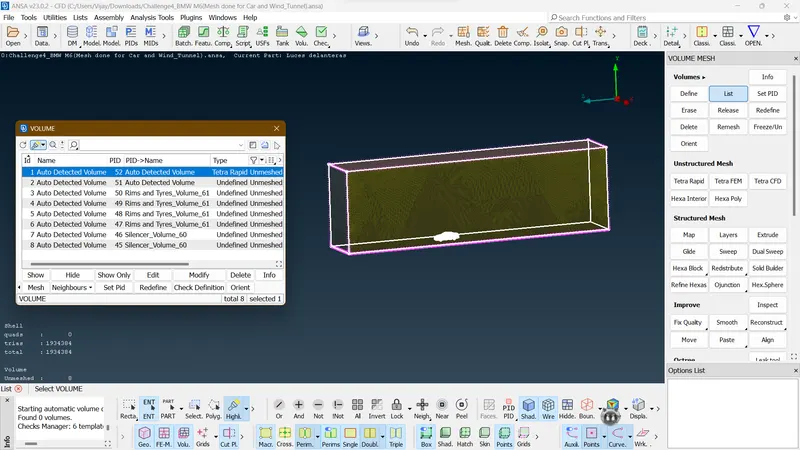
- It will show you the volume list, by default it will detect the volumes.
- Volumes are nothing but ANSAs closed geometry, which is closed in the TOPO mode.
- Few volumes are useful and other you can delete if not necessary.
- We will be only meshing the volume that occupied by parent geometry thickness.
- As you can see the volumes their will be a particular volume which is connected with the wind tunnel then you can proceed further for V.Mesh
FIG 1. Before the TOPO cleanup
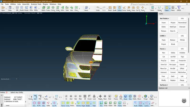
FIG 2. After the TOPO cleanup
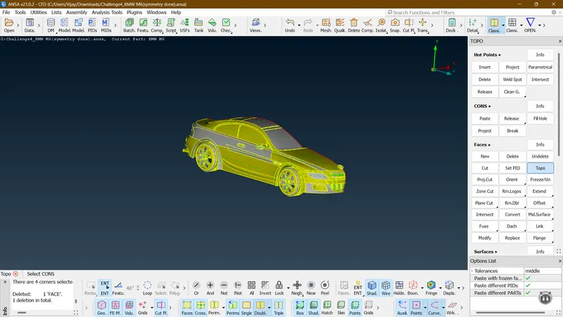
FIG 3. Assigning of PIDs for different parts
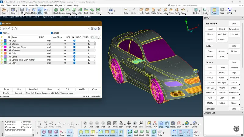
FIG 4. Mesh done with Zero Off elements
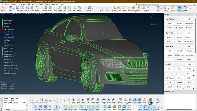
FIG 5. Symmetry done
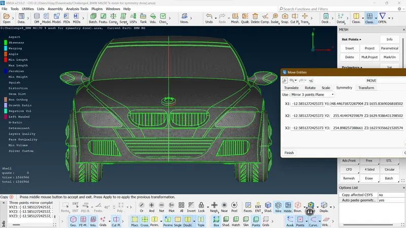
FIG 6. Wind Tunnel mesh done
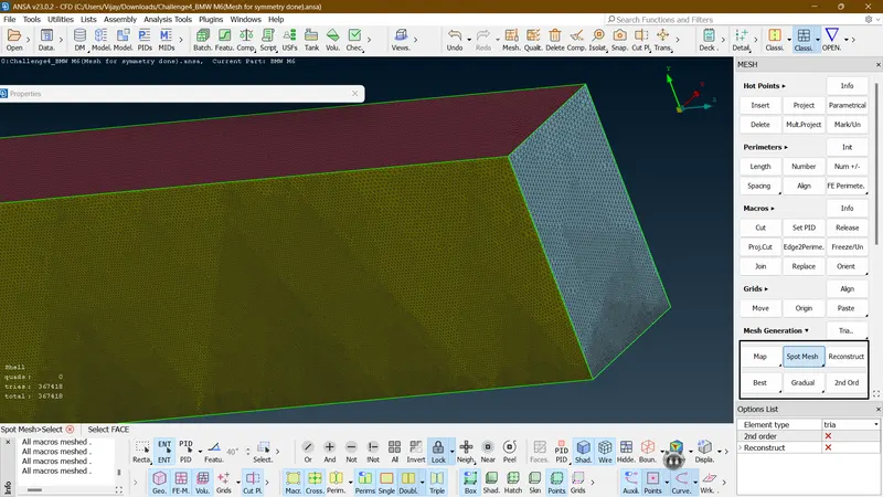
FIG 7. Showing the connection of car and wind tunnel in one volume
RESULT:
- The main model is cleaned up and fully refined
- Mesh done successfully for every part in the car with the different parameters and criteria.
- Wind tunnel created and meshed successfully.
CONCLUSION:
The given Car model and wind tunnel has been cleaned up and with the given target lengths and element type it is successfully meshed.