Week 3 Challenge : CFD meshing on Turbocharger
AIM: To check for the geometrical errors then create and assign PIDs. Perform surface mesh with the given target lengths as per PIDs.
- Blade stage_1 = 1 mm
- Blade stage_2 = 1 mm
- Impeller = 2 mm
- Shaft rotor = 1 mm
- Turbo casing = 5 mm
- Compressor casing = 5 mm
- Inlet casing cover = 5 mm
- Perform Volumetric mesh for the required volumes.
TOOLS USED:
Classic TOPO:
- Checks: It is used to check the errors in the model.
- Geometry: It is useful to find errors in the geometry
- Hot Points:
- project: It projects the points in the selected cons or faces.
- Parametrical: It insert hot points parametrically along the length of selected CONS Or Curve.
- CONS:
- Fill hole: It fills the holes and openings.
- Release: It releases the topology of selected CONS.
- Project: It projects the curves or cons on faces and cut them.
- Faces:
- New: It is useful to create a new face anywhere in the geometry.
- Delete: If any unwanted part is created it will remove it.
- TOPO: It merges the CONS.
- Intersect: Intersects the two different faces.
- ENT: It can select any entity one by one.
- PID: It can select one by one or with the box selection.
- Not: It disappears the visible entities.
- All: Bring back all the entities to the current window.
- Compress: It compress the unused entities.
- Auxiliaries:
- Fine: It increase or decrease the resolution of selected CONS or curves.
Classic Mesh:
- Perimeters:
- Length: It is defined to mention the distance of the nodes.
- Macros:
- Cut: Cut a macro area with two perimeter nodes or hot points.
- Mesh Generation:
- Spot mesh: It is the tool to mesh the geometry by nodes on the surface.
- Mesh parameters: For improvement of mesh generation.
- Quality criteria: For the quality presentation of the geometry.
- PIDs: Property list for specifications of properties and boundary condition.
Volumetric Mesh:
- Volumes:
- Define: Definition of volume entites.
PROCEDURE:
- Open the model in the ANSA.
- To make the model visible with the faces use the ‘shadow tool’ present in the bottom of the window.
- First go for the “checks>geometry” and check how many and where are the errors and then execute.
- To create a new face there are different methods to use one of them is by using the tool “topo>faces>new>existing surface.”
- For checking the overlapped surface, you can use “Faces>TOPO.”
- Delete the overlapped surface by using universal delete option by selecting the surface which you want to delete.
- If any extended surface is located first intersect by using “faces> intersect” tool and delete the surface once it forms a con.
- If you use release tool “Cons>Release” it will separate triple con into three different single cons.
- If you do ‘TOPO’ from ‘faces’ it will do the opposite of the release, it will merge the cons to form a double con.
- If you don’t want a face or a line in the model, you can remove it by using “TOPO>Faces>Delete.”
- After the topology cleanup assign the PIDs for every component {as shown fig (1)} by using PIDs properties. And by using tools from feature selection: ENT & PIDs>PID/PID region.
- After completion of Topology cleanup let us move to the mesh generation.
- Whenever you start with the mesh first step should be giving its length by using “Classic Mesh>perimeters>length.”
- In the length option set the Perimeters and Macros length as per the requirements given in the aim.
- After mentioning the length, give the target length and element type as ‘tria’ in the Mesh parameters and check the quality criteria and change the min and max length.
- After giving the lengths mesh the components individually with the defined lengths.
- Every component has different criteria, so it is changed accordingly.
- After giving the parameters deploy the Mesh by using tool “Mesh generation>Spot mesh.”
- After meshing you will find some meshed area is erased. Its because with two target lengths from two different faces meeting on the same line makes them erased.
- For that you can choose only CONS in the perimeters of a face and leave the Macros as it is, so that Macros does not change the lengths upon meeting and does not erase.
- After meshing the erased surface, you can observe the common point of the two different faces with different target lengths are merging with each other.
- But it is disturbing the mesh of small target lengths, so in order to correct that, you can use the tool (“Macros>cut”) it will cut into the faces and create the new face for the disturbing surface.
- After the surface mesh proceed to volumetric mesh.
- Volumetric mesh is a kind of 3D element mesh.
- After entering the V.Mesh your first task is to define the model by using (“V.Mesh>Volume>Define.”)
- In that you can choose it as a visible model or whole database as per your requirements.
- Choose the whole database and click ‘ok’.
- It will show you the volume list, by default it will detect the volumes.
- Volumes are nothing but ANSAs closed geometry, which is closed in the TOPO mode.
- Few volumes are useful and other you can delete if not necessary.
- We will be only meshing the volume that occupied by parent geometry thickness.
- Define the volumes for each component which are present.
- Mesh it as ‘Tetra CFD’ mesh (as shown in fig{3}).
- And then by hiding some tetra elements you can check the cross section it is done correctly or not (as shown in fig), those are basically tetra elements.
- Finally V.Mesh also done successfully (as shown in fig{4}).
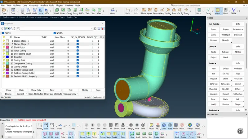
FIG 1. Assigning of PIDs.
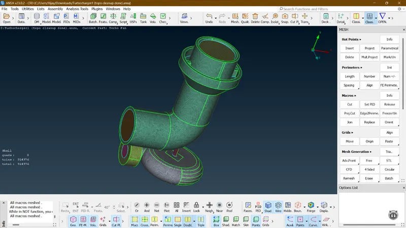
FIG 2. Classic Mesh.
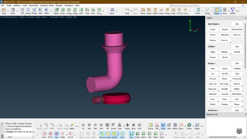
FIG 3. Meshed with V.Mesh.
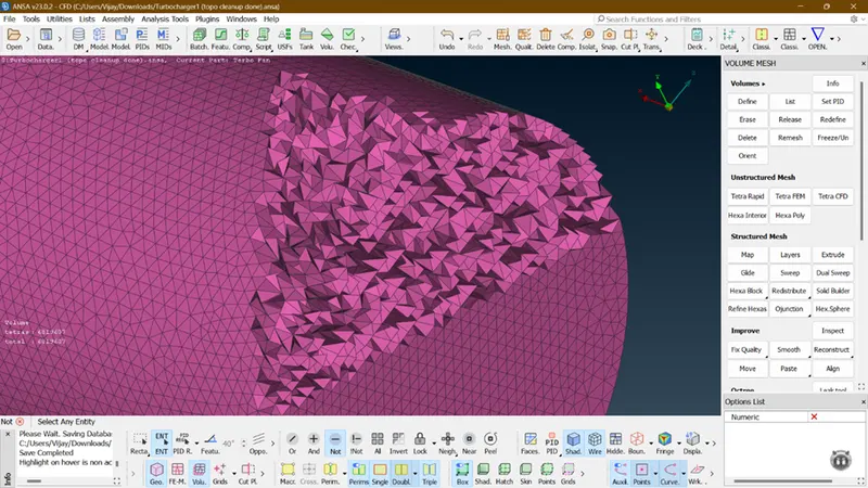
FIG 4. Cross section of Tetra Elements.
RESULT:
- The main model is cleaned up and fully refined
- The mesh was fine and cross section was also very good.
CONCLUSION:
The given model has been meshed with the given target lengths and element type and successfully meshed with volumetric mesh.