Week 2 Challenge : Surface meshing on a Pressure valve
AIM: To check the geometrical errors and perform topology cleanup and with three different Target lengths mesh the model.
Target length: 1mm, 3mm and 5mm.
Element type: Tria
TOOLS USED:
Classic TOPO:
- Checks: It is used to check the errors in the model.
- Geometry: It is useful to find errors in the geometry
- CONS:
- Fill hole: It fills the holes and openings.
- Faces:
- New: It is useful to create a new face anywhere in the geometry.
- Delete: If any unwanted part is created it will remove it.
- Undelete: Any deleted part can be retrieved back with this tool.
- ENT: It can select any entity one by one.
- PID: It can select one by one or with the box selection.
- Or: It keeps visible entities only.
- Not: It disappears the visible entities.
- Lock: Lock the current entities visible.
- All: Bring back all the entities to the current window.
- NeighB: Bring back the neighbours of the 1st level entities.
- Loop: It selects the cons which are looped in.
Classic Mesh:
- Perimeters:
- Length: It is defined to mention the distance of the nodes.
- Mesh Generation:
- Spot mesh: It is the tool to mesh the geometry by nodes on the surface.
- Mesh parameters: For improvement of mesh generation.
- Quality criteria: For the quality presentation of the geometry.
- PIDs: Property list for specifications of properties and boundary condition.
MESH: To perform CFD simulations, the computational domain is divided into small sub-regions called elements or cells. These cells collectively form the mesh, which is a grid-like structure that discretizes the domain. The mesh is composed of nodes or vertices that define the corners of each cell, and edges or faces that connect the nodes and form the boundaries of the cells.
PROCEDURE:
- Open the model in the ANSA.
- To make the model visible with the faces use the ‘shadow tool’ present in the bottom of the window.
- First go for the “checks>geometry” and check how many and where are the errors and then execute.
- To create a new face there are different methods to use one of them is by using the tool “topo>faces>new>existing surface.”
- If you don’t want a face or a line in the model, you can remove it by using “TOPO>Faces>Delete.”
- And patch the holes by remaining methods to create a face by help of various tools like “loop, ENT” and to create “Planar, fitted and fill hole.”
- After the patching, go to the checks and check for the errors.
- If you get any error, it could be a triple con, so it is not an error it is a warning that you have triple con.
- Before meshing delete the small faces present in the model. By removing the line by using the tool “faces>cut.”
- After that assign the PIDs for inlet, outlet, body, spring, column, base surface, and valve head {as shown fig (1)} by using PIDs properties. And by using tools from feature selection: ENT & PIDs>PID/PID region.
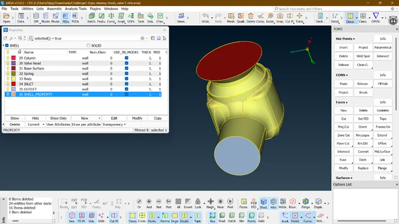
FIG 1. Assigning of PIDs.
- After completion of Topology cleanup let us move to the mesh generation.
- Whenever you start with the mesh first step should be giving its length by using “Classic Mesh>perimeters>length.”
- In the length option set the Perimeters and Macros length as ‘1’.
- After mentioning the length, give the target length as ‘1’ and element type as ‘tria’ in the Mesh parameters and check the quality criteria and change the min and max length as 0.5 and 2.
- After giving the parameters deploy the Mesh by using tool “Mesh generation>Spot mesh.”
- Now measure between the nodes it will be approximately ‘1.’
- After getting a fine you can procced further for analysis.
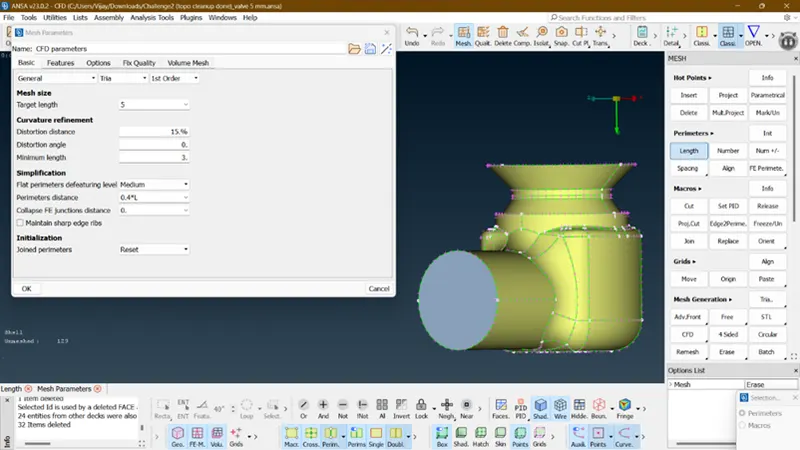
FIG 2. Setting the Target Lengths.
Now as of the challenge, 3 cases are required as follows:
CASE 1:
- With the target length= 1, minimum and maximum length are 0.5 & 2.
- The quality of the mesh is fine and no uneven surface is present.
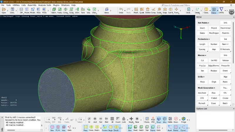
FIG 3. Full body Mesh (With Target Length= 1)
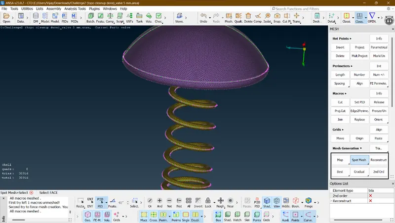
FIG 4. Showing the fine mesh of Valve Head and Spring
CASE 2:
- With the target length= 3, minimum and maximum length are 1 & 5.
- The quality of the mesh was fine on the body but the spring and valve head were slightly uneven, so if it goes for any further analysis, it will give some bad results.
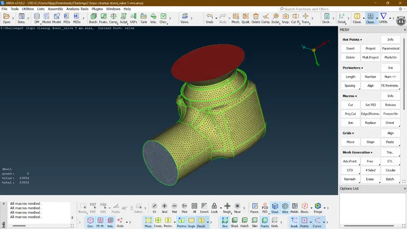
FIG 5. Full body mesh (With Target Length= 3)
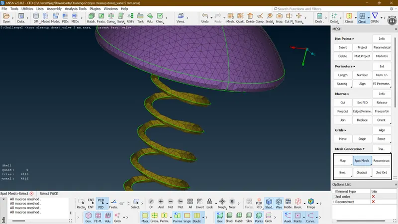
FIG 6. Showing some uneven surface
CASE 3:
- With the target length= 5, minimum and maximum length are 3 & 7.
- The quality of mesh on the body was good but Valve Head and Spring is uneven with the mesh as going further with this model the results will be worse.
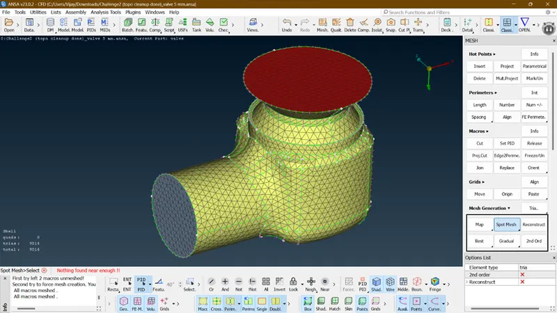
FIG 7. Full body Mesh (With Target Length= 5)
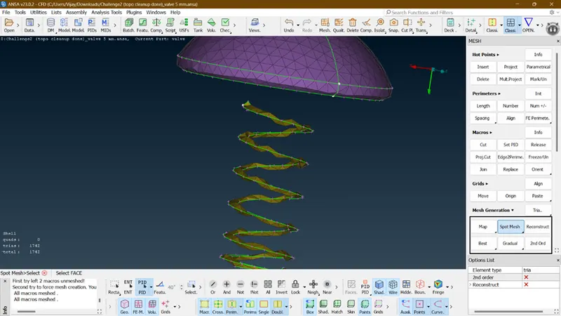
FIG 8. Uneven Mesh
RESULT:
- The main model is cleaned up and fully refined
- With three given target lengths I disclose that, with target length=1 the mesh is highly recommended as it gives the best results.
- The remaining 2 target lengths are not giving good results.
- As of target length=5, if the target length is greater than the surface length the mesh will not happen.
REASON:
- The meshing depends on the size and complexity of the geometry.
- By reviewing the three cases, case 1 will be the best suited for further process
- Because it justify the every component present in the model.
CONCLUSION:
The given model has been meshed with the given three target lengths and element type.