Week 4 Challenge : CFD Meshing for BMW car
Aim:
To check and solve all geometrical errors on half portion and Assign appropriate PIDs and also to Perform meshing with the given Target length and element Quality criteria. we also need to perform symentry and to create wind tunnel.
Given:
the target lengths given are
- Body - 3 mm
- Lights - 4 mm
- Grills - 1 mm
- Rims and Tyres - 2 mm
- Optical Rear view mirror - 2 mm
- Window - 2 mm
- Silencer - 3 mm
- Logo - 1 mm.
Also as per video skewness limit will be 0.5.
Procedure:
The following were the stages to perform
initial setup
Topological cleanup
check for errors
assigning PID's
component wise surface mesh
creating wind tunnel
surface meshing wind tunnel
Volumetric meshing the whole components
1.Initial setup:
- initially we need to import to import the model into ANSA interface
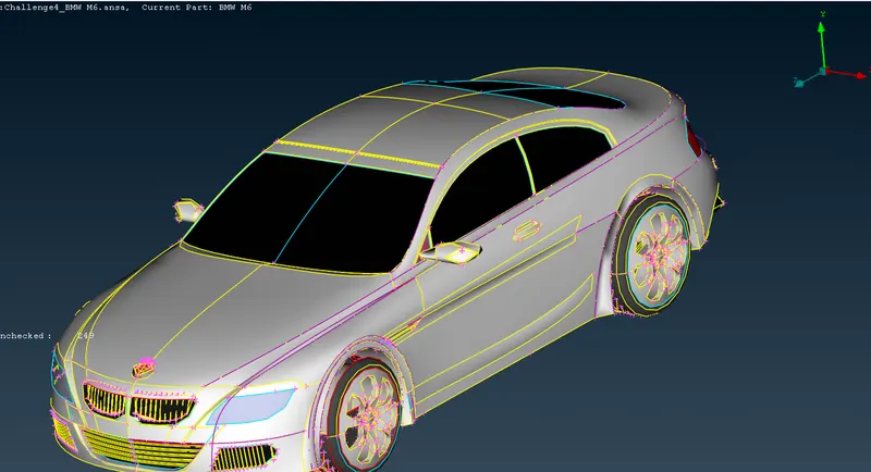
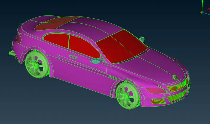
- then check for any geomentrical or surface errors vissible for example in tyre areas there is some error which shows oversizing of default meshing value
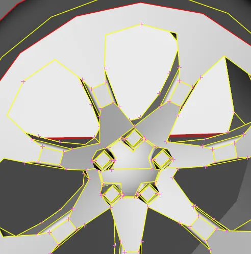
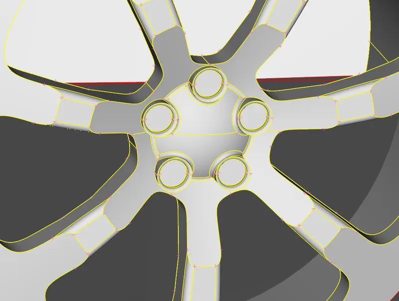
- in order to rectify this type of error select all models and give mesh length to 1 mm which solves it
- then select delete option and select half of the components by view in top view like
-
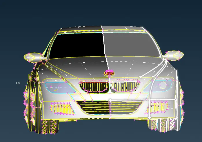
- dont forget to deselect the logo which was commonly present
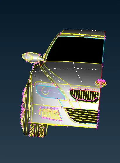
- we further going to perform all the topological cleanup and meshing and then we gonna mirror it .
2.topological cleanup
- initially we gonna perform topo cleanup by resolving the issues such as single cons, triple cons and crack in model
- for topo cleanup we gonna make 4 seperate volumes such as car inner, tyres and silencer
- remember the concept there should be common volume inside car so all the excess faces abd volumes inside car can be neglected or deleted
- only outer surface of car should remain all the inner surface can be neglected
- please refer to the picture
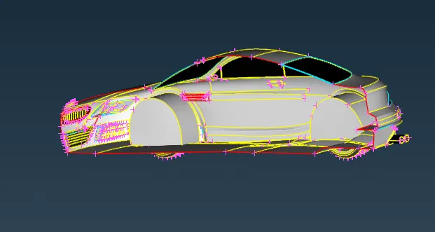
- all this inner components should be solved like this
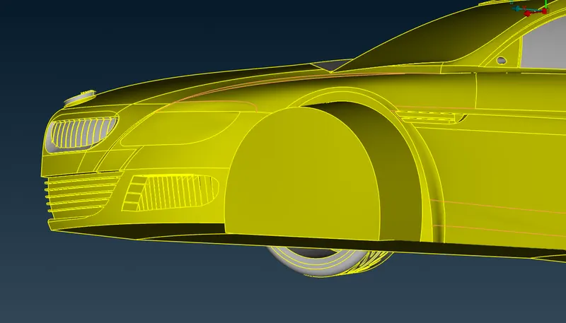
- like this picture components are soved for single, triple cons and errors
- for this we use tools such as delete, cut faces, new faces , cons paste , release option and topo cleanup.
- also hold ctrl and shift to see hidden frame views
- make sure to isolate each pid or components such as grills, logo, window, rear view mirror, silencer, wheels and rim and silencer and make sure for each selection you need to rectify error completely because if we misses it will be double work for us to perform meshing
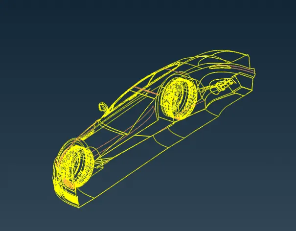
- make sure that final component should contain only double cons also check for interference of any face into any components and delete it
3.check for errors
after topo go to checks>> geomentry>>execute >> ehich shows any error in geomentry
reolve the issue if there is any like collapsed cons, single cons, triple cons , crack in surface ,etc.
4.Assigning PID's
we need to assign each PID specifically
go to property manager right click>>new>> pshell>>pshell to create PID's accordingly
create the following PID like body; rms and tyres; grills ; logo; window;rear view mirror; light and silencer
apply each PID by apply option under specific PID
5.Component wise surface mesh:
initially go in following order which states to mesh body PID last
refer to the given details like
- Body - 3 mm
- Lights - 4 mm
- Grills - 1 mm
- Rims and Tyres - 2 mm
- Optical Rear view mirror - 2 mm
- Window - 2 mm
- Silencer - 3 mm
- Logo - 1 mm.
> Logo
required target length for logo was 1mm
isolate logo entities
go to mesh parameters and provide target lengths as 1 mm and type as tria and save mesh parameters with name tag 1 mm mesh length
go to quality criteria select skewness as 0.5; min length as 0.5; max length 2mm; angle parameters and also select calculation as fluent for all.
go to classic mesh and length perimeters and select all components and give mesh length as 1mm and also macros as 1mm
then also go to mesh >> spot mesh >> visible and click ok
turn on hidden view to see the errors specify colors for each type of errors like min and max length ,skewness;
when there is error go to grid >> move to move grid as a trial and error to rectify issues.
you can also check the no of off values in bottom left corner
repeat the same procedure for all the PID's except body PID the only difference is min; max length and target lengths as follows
- Lights - target length 4 mm min length 2mm ; max length 6mm:
- Grills - target length 1mm min length 2mm ; max length 6mm:
- Rims and Tyres - target length 2 mm min length 2mm ; max length 6mm:
- Optical Rear view mirror - target length 2 mm min length 2mm ; max length 6mm:
- Window -target length 2 mm min length 2mm ; max length 6mm:
- Silencer - target length 3 mm min length 2mm ; max length 6mm:
after all this PID's you only left with body PID.
in order to mesh the body Pid give mesh perameters as 3mm target lengths and quality criteria and perform macros in mesh deck
while performing perimeters select all the body pid faces and deselect the edges which are in contact with other pid's
we are performing this particular pid in order to that if we give same macros length for all it will spoil the mesh of other pid in contact with body
turn on hidden view to see the errors specify colors for each type of errors like min and max length ,skewness;
when there is error go to grid >> move to move grid as a trial and error to rectify issues.
wind tunnel:
take length of car as X
in windtunnel car should be present at 4X distance from front and 6x distance from rear and x distance from side
height should be of 3X distance
according to this creatye points and connect it through curves option and create faces like cuboid
assign differnt pid's for different faces of wind tunnel
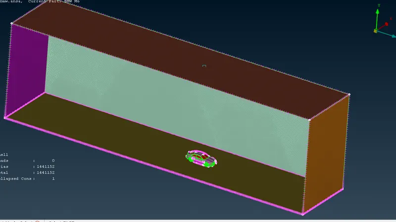
mesh top face with 100mm target length and bottom face with 20 mm target length
and on all the four edges give perimeter>> spacing with factor of 1.1 from 20 to 100
then mesh them accordingly it will indicate that mesh on bottom is denser than top
then perform volumetric mesh the whole db to find the volume available
delete other volumes except volume between tunnel and car
then process to tetra cfd meshing
RESULT:
thus meshing of bmw car is done