Week 4 Challenge : CFD Meshing for BMW car
Aim:
For the given model, check & solve all geometrical errors on half portion & Assign appropriate PIDs. Perform meshing with the given Target length & element Quality criteria. After meshing the half model, Do symmetry to the other side.
Solution procedure :
- Import the CAD model, identify & cleanup of the topological / geometry errors.
- Do a Geometry check-up.
- Set-up of relevant PIDs.
- Defining the element size or length & set the mesh parameters , selection of meshing type & generating surface mesh of the CAD model .
- Resolve the errors in the surface mesh.
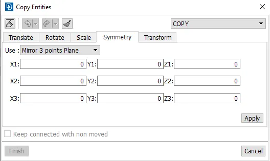
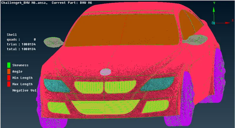
- Create the Full Model Using Symmetry Option.
- Create a wind tunnel for external flow CFD analysis & surface mesh of wind tunnel.
- Generating volumetric mesh.
Importing CAD the model :
- To import the CAD model we follow below steps,
Go to file -> open -> browse the location of the CAD model -> select it click on open.
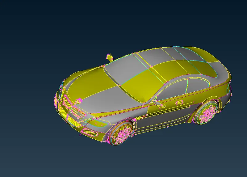
Identify & cleanup of the topological / geometry errors :
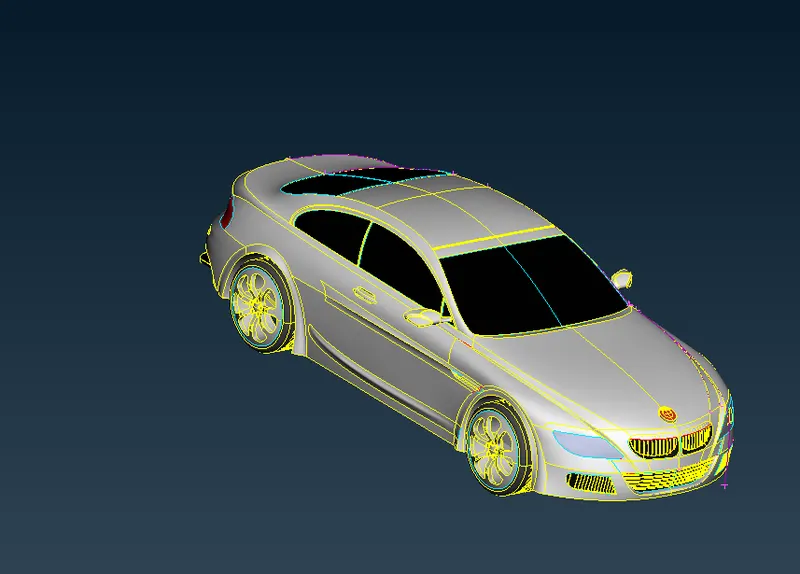
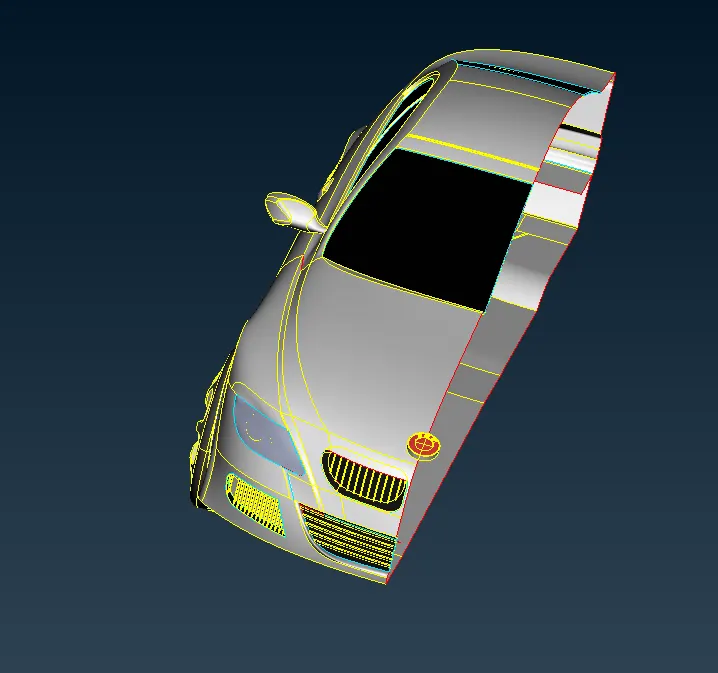
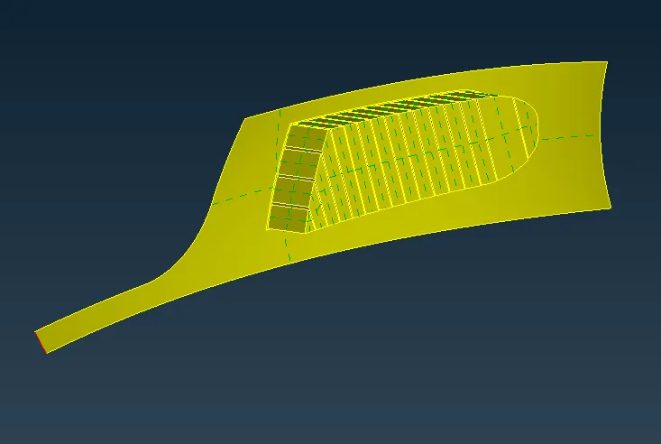
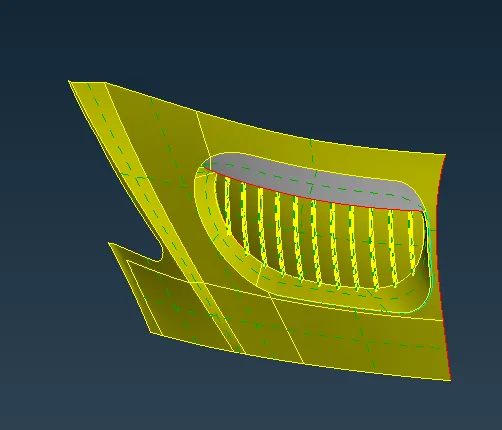
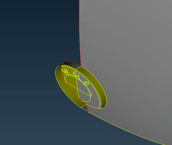
- In the below image you can observe that we have deleted only body part & left the logo as it is , because logo is not symmetrical where as whole body is symmetrical i.e., same on both sides .
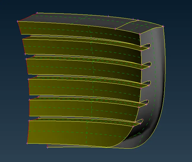
- Grill:
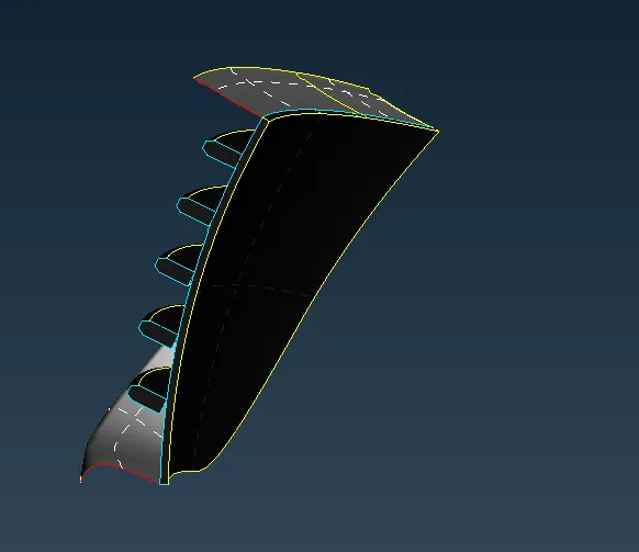
- The below image is the front central bottom grill after topo cleanup .
- Logo:
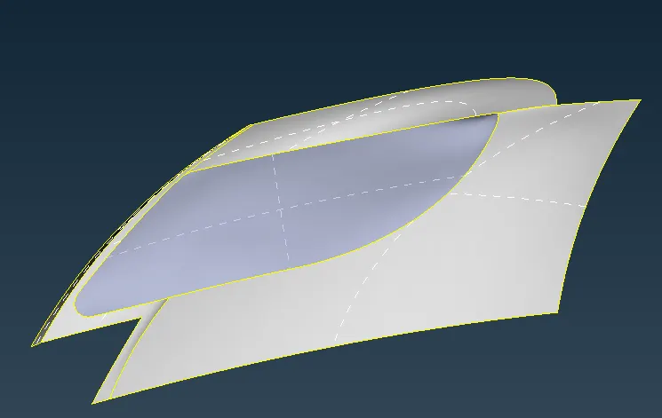
Front & side windshield/windows :
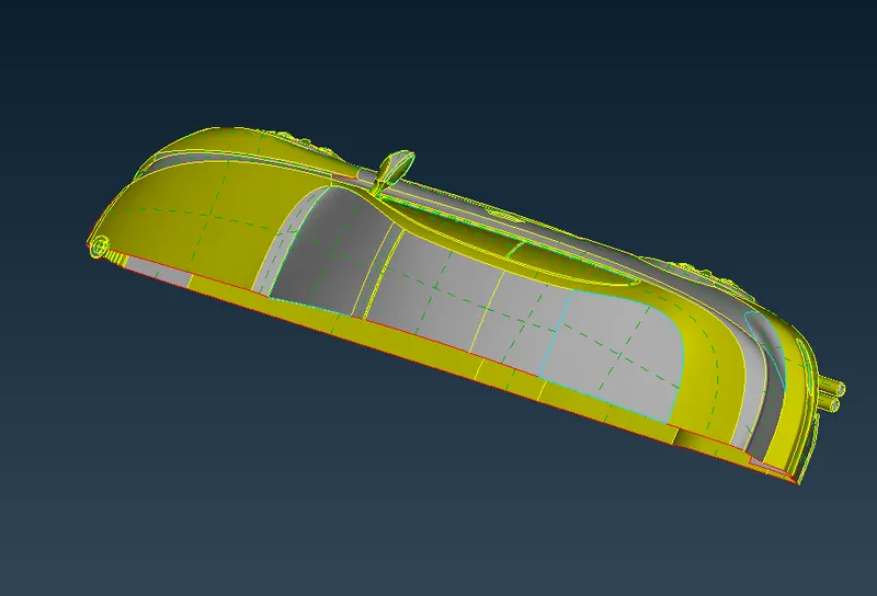
- In the below image we can see clearly the thickness of window which we need to delete.
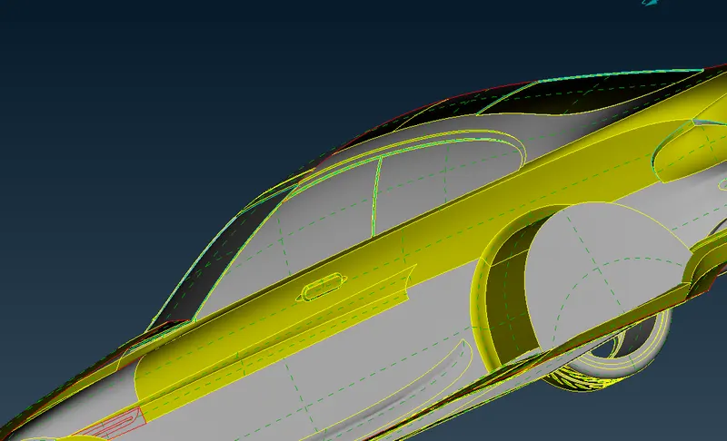
- The below image is of the front & side windows after topo cleanup.
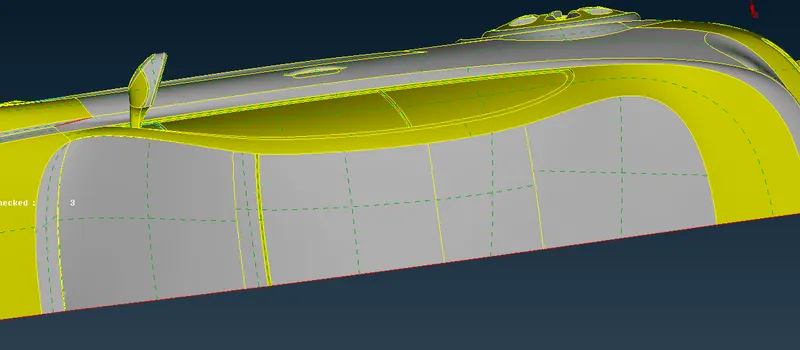
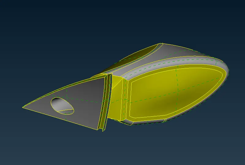
- The below image is of the mirror after topo cleanup .
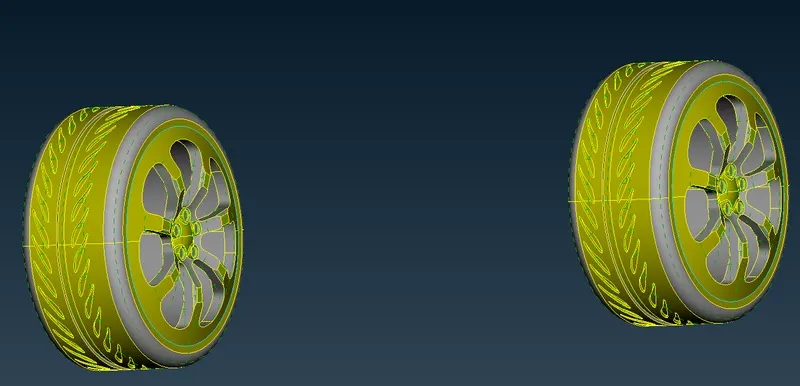
g) Rims & Tyres :
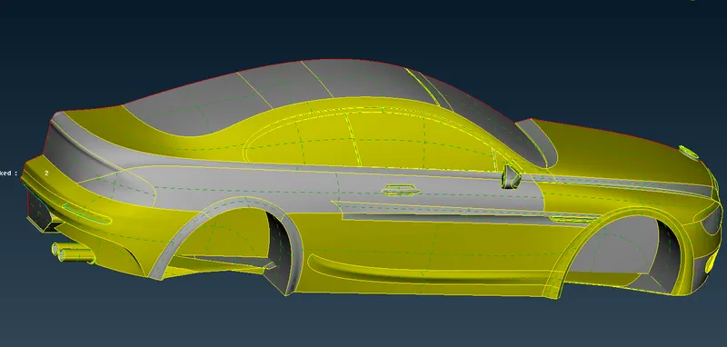
- The below image is of the body part from outside before topo cleanup.
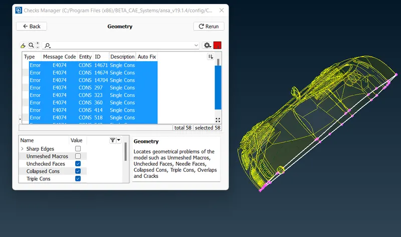
Geometry check-up :
Setting-up of relevant PIDs :
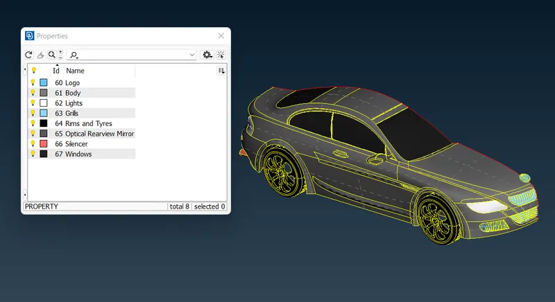
- If you open properties manager at the top , you will have some default PID's which are assigned. We have to create new PID's to assign for our components. Inorder to create new PID , right click on properties manager -> click new -> then select pshell -> then again select pshell -> then give name in the popup box -> then ok .You can change the colour by double clicking on the colour box -> then ok .
- In the similar way create PID for all the components.
- Then next thing is assign these PID's to the components of the geometry .
- To apply , we select /click on the PID to apply in the PID manager -> then right click on it -> then click on apply -> then in the geometry select the cross hatch of the surface you want to assign -> then middle click . In the similar way we have to apply PID's we have created . To give the PID we select with the different type of selection available to select the exact surface needed.
Surface meshing:
We need to mesh the components individually since the given mesh targets are different for each PID regions.
Assign the mesh parameters & quality parameters for each PID accordingly, assigning the correct min & max length will reduce mesh failure & off elements.
Quality criteria for logo & grills region:
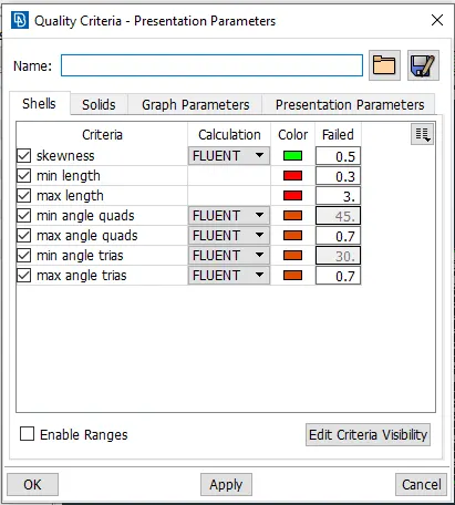
Logo & grill surface mesh:
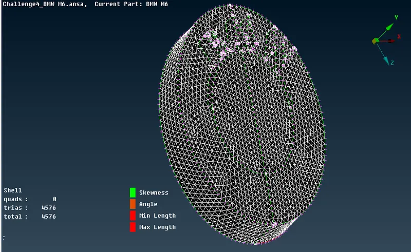
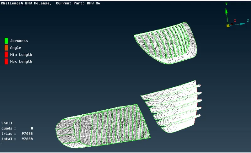
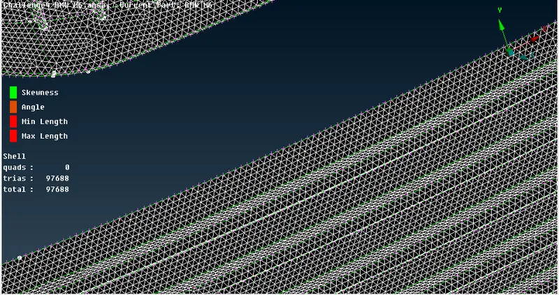
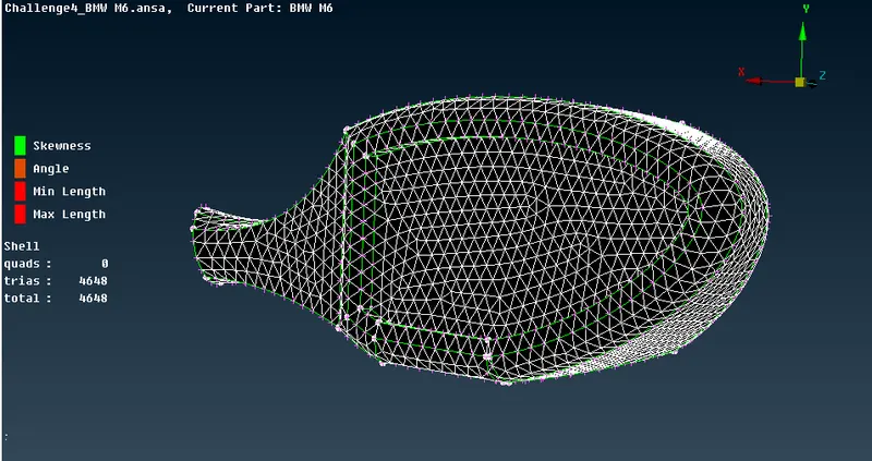
Rims & tyres, window & rear view mirror surface mesh:
Quality criteria & mesh parameters:
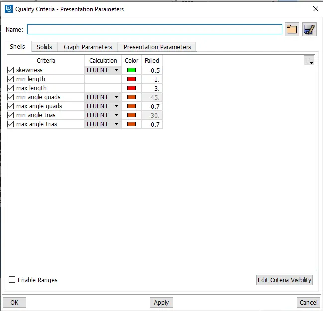
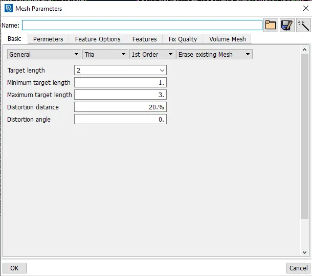
Surface mesh:

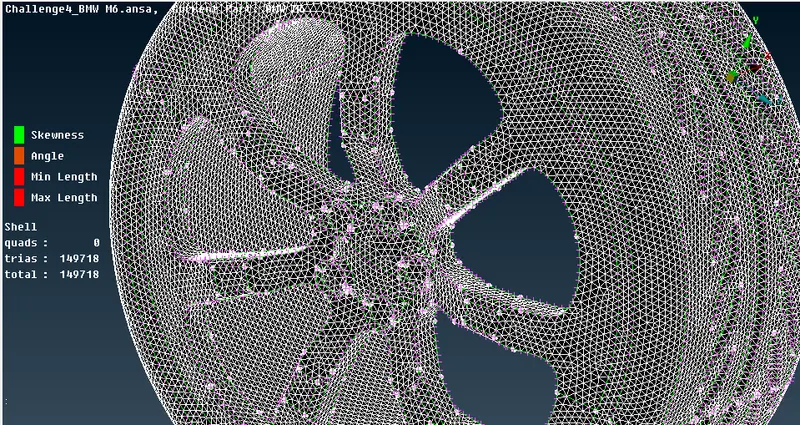
Silencer & lights:
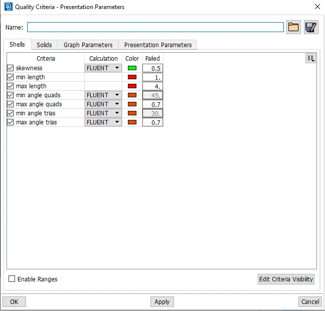
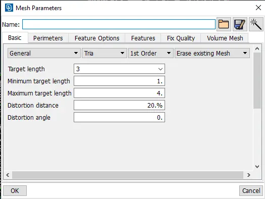
Quality criteria & mesh parameters for silencer:
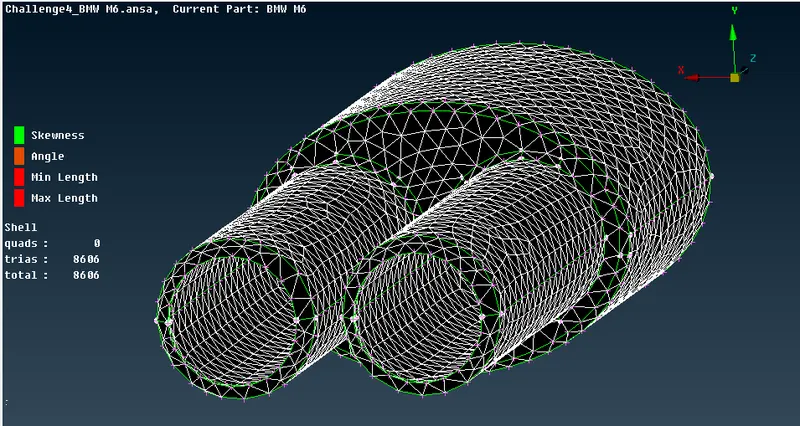
Surface mesh:
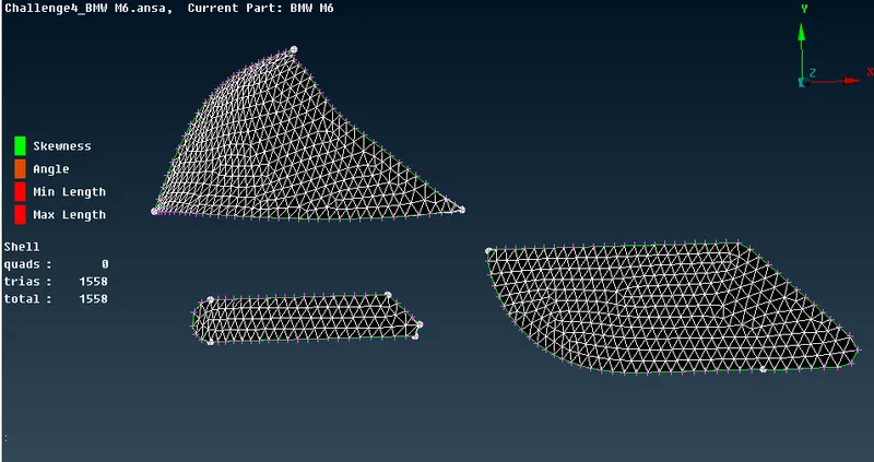
Body surface mesh:
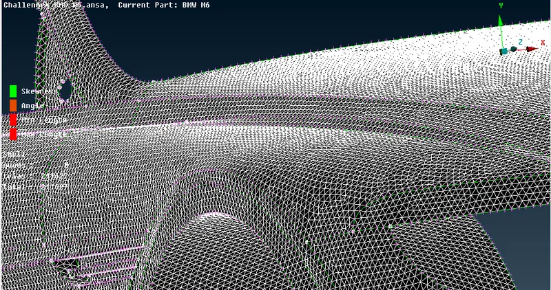
Since body PID region is in contact with various other PID, the mesh length variation at the boundary region of 2 different PID cause the mesh to erase or cause mesh failure. Therefore, While entering the perimeters under length in mesh drop down. Select the regions which are not in contact with the other meshed PID regions. This helps in avoided the mesh to be erased & can later be edited to erase the off elements.
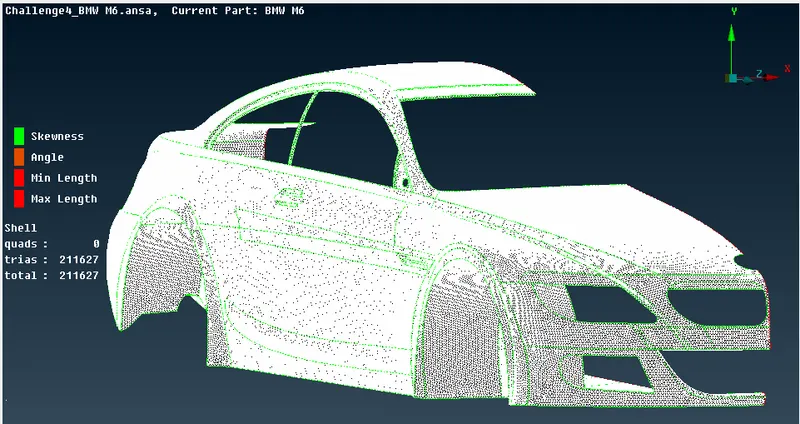
After meshing, we can choose re-construct under shell mesh to reduce the off elements. & later the remaining off elements can be edited manually.
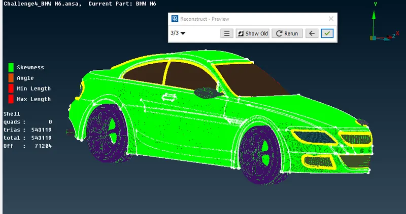
Final surface mesh of car model:
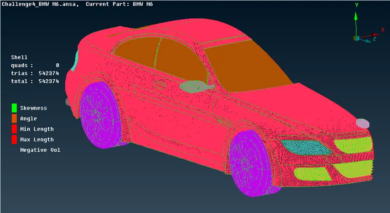
Performing symmetry on the car model:
CREATION OF WIND TUNNEL:
To create the wind tunnel first calculate the length of the car
Then goto > POINTS > NEW & create points in all directions according to the directions of the wind tunnel
Create three nodes that are responsible to draw a plane
Goto surfaces > PLANE & draw a plane using those three nodes & replicate the same plane using translation symmetry
Repeat the same procedure for the other two sides
Goto CONS > INTERSECT to intersect all planes & delete the unwanted surfaces
Thus wind tunnel is created & assign PID's to differentiate INLET & OUTLET
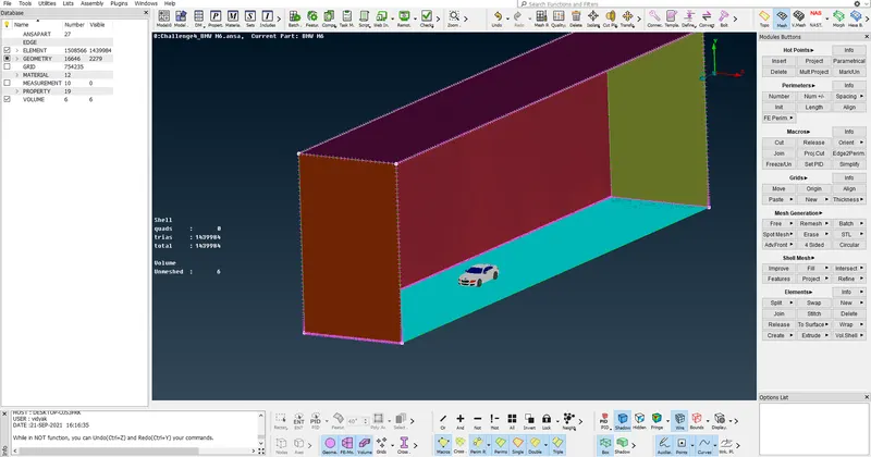
Wind Tunnel Mesh:
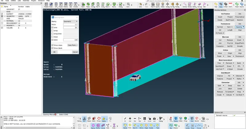
Sides of the bottom of the tunnel of length 20mm
Sides of front & back as of length 50mm
Sides of top of the tunnel of length 100mm
Then goto PERIMETERS > SPACING > CONSTANT LENGTH & assign min value as 20mm & max as 100mm & assign to all front &
backsides
Conclusion:
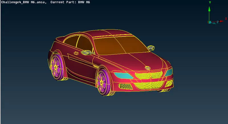
BMW car model is topo-cleaned & surface meshed appropriately.Wind tunnel is created & surface meshed with reference to the car model size. Different volumes of the car model is created since the silencer & tyres are not connected to the car body. Volumetric mesh is not done.
Mesh model Link:
https://drive.google.com/file/d/1vlSLAIo5Hk65BuNFRqiz8dJ6ywrahYL0/view?usp=sharing