Week 4 Challenge : CFD Meshing for BMW car
CFD MESHING OF A BMW M6 CAR
PROBLEM STATEMENT :
For the given model, check and solve all geometrical errors on half portion and Assign appropriate PIDs. Perform meshing with the given Target length and element Quality criteria. After meshing the half model, Do symmetry to the other side.
Target lengths for the different parts of a model are as follow:
- Body - 3 mm
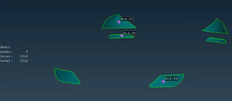
- Lights - 4 mm
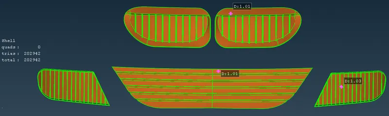
- Grills - 1 mm
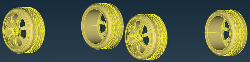
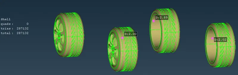
- Rims and Tyres - 2 mm
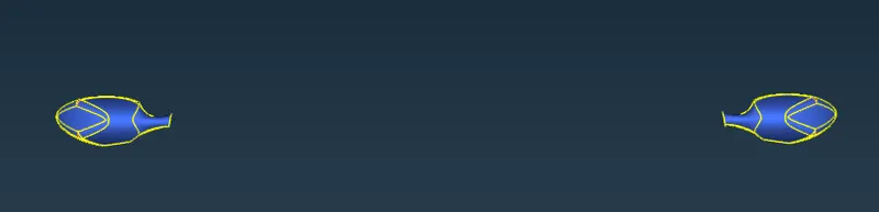
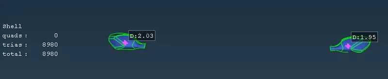
- Optical Rear view mirror - 2 mm
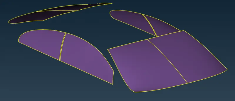
- Window - 2 mm
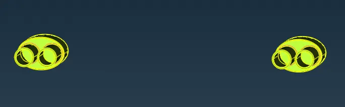
- Silencer - 3 mm
- Logo - 1 mm
AIM :
To perform the Surface meshing of the given BMW model with the given mesh parameters (i.e. target lengths and quality criteria ) after thorough geometrical cleanup and appropriate PID creation.
Target lengths for the different parts of a model are as follow:
- Body - 3 mm
- Lights - 4 mm
- Grills - 1 mm
- Rims and Tyres - 2 mm
- Optical Rear view mirror - 2 mm
- Window - 2 mm
- Silencer - 3 mm
- Logo - 1 mm
PROCEDURE :
1. GEOMETRICAL CLEANUP.
2. PID CREATION .
3. SURFACE MESHING .
4. SYMMETRY CREATION .
5. WIND TUNNEL CREATION AND MESHING .
- GEOMETRICAL CLEANUP :
1. Firstly import the given geometry in ANSA GUI.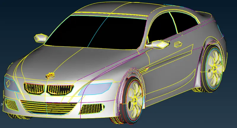
fig : Given BMW model in PID mode .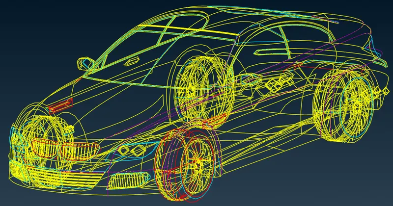
fig : Given model in WIRE FRAME mode .
2. We can observe in the given geometry there a lot of single cons (red color con) and triple cons (blue color con) present . Therefore the topo errors can be resolved part by part by isolating them and as the geometry is symmetric one half of the model can be deleted for convenience.
3. The resolution of the geometry is very poor , it can be resolved using LENGTH option [i.e. MESH>PARAMETERS> LENGTH ] in mesh deck by setting to 1mm inorder to have smooth curves for better physics.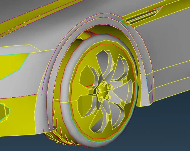
fig : poor tyre resolution .
TOPO CLEANUP OF GRILLS :
1. Inorder to perform geometry clean up for SIDE , UPPER and BOTTOM GRILL we have to isolate the part and lock it by using !NOT mode and LOCK option.
2. The topo errors can be viewed in wire frame mode inorder to delete all the unwanted surfaces by using universal DELETE option.
3. Objective here is to create a common volume inside the car geometry and modify the required surfaces .
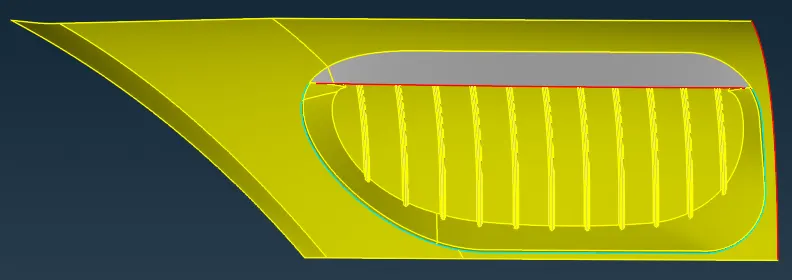
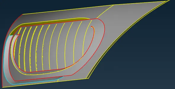
fig : topo errors present in the upper grills
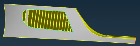
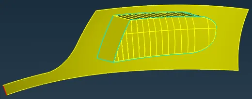
fig : topo errors present in the side grills
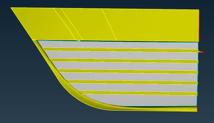
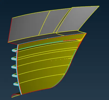
fig : Topo errors present in the bottom grills
4.The ribs or intake grill must form a common volume so the unwanted closing of ribs must be done in all the grills .
5. Tools useful in topo clean up of grills are Not , Project(CONS) , New(Faces) , Cut(Faces) , Topo(Faces) , Delete(Hot Points) , Extend(Faces) , Parametrical(Hot points) , Multi project(Hot points).
TOPO CLEANUP OF LOGO , RIMS AND TYRES :
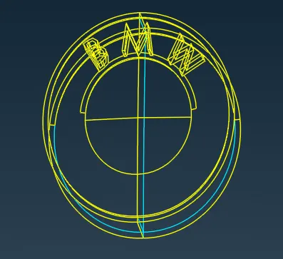
fig : triple con error in logo
1. Major topo cleanup in the logo part is in the bottom surface where the triple con error is present , also the unwanted surfaces can be deleted .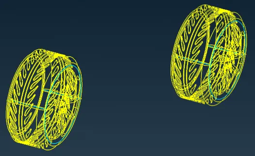
fig : topo error in the tyres and rims
2. The triple cons and overlapped surfaces can be removed by hiding few surfaces and deleting unecessary surfaces. Also the common surfaces can be deleted.
TOPO CLEANUP OF WINDOWS :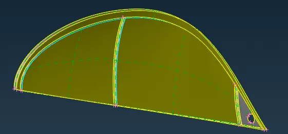
fig : Topo error on the side window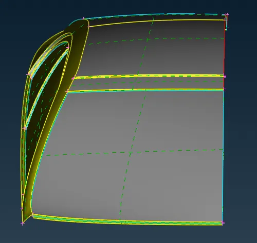
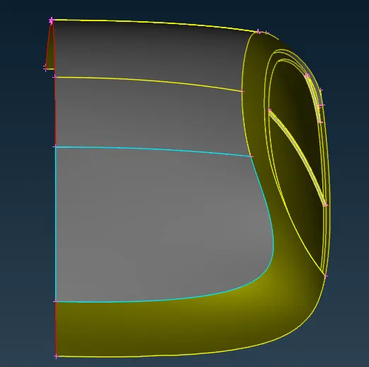
fig : Topo error in the front and rear windshield respectively
1. The triple con and single cons present can be cleaned by isolating the surface by realeasing the cons .
TOPO CLEANUP OF LOWER BODY :
1. A lot of overlapping and penetrating surfaces are present in the lower body obstructing the tyre plane .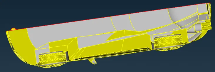
fig : Lower body surface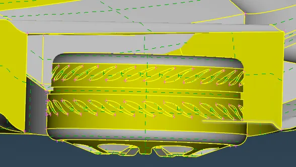
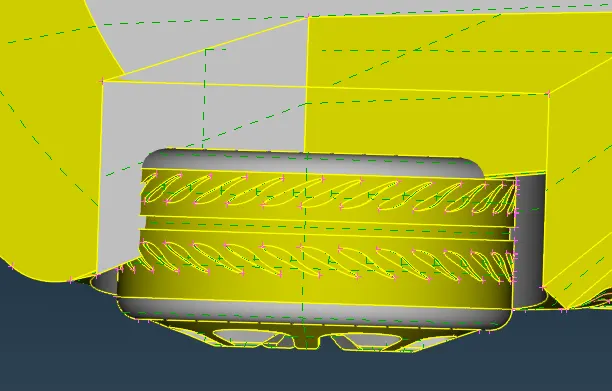
fig : Penetrating surfaces in the floor
2. The surfaces can be removed by intersecting the plane and then carefully removing the unwanted surfaces i.e. by using INTERSECT option .
3. The footprint of the surfaces play an important role in deleting the unwanted and uneven surfaces , so CONS2CURVE [i.e.TOPO DECK > CURVES > CONS2CURVE] option can be used to trace the surface curves .
4. Finally after resolving all the topo error only one single con curve must be present by checking in CHECKS manager as it is a remnant formed after the deletion of half of the model .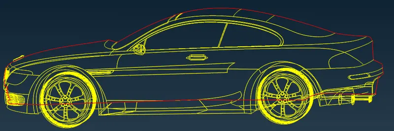
fig : Topo cleaned model in wire frame mode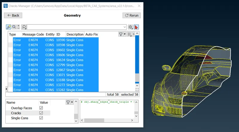
- PID CREATION :
1. After topo cleanup the next is PID creation and assignment in pre-processing. The PIDs can be created in the properties deck .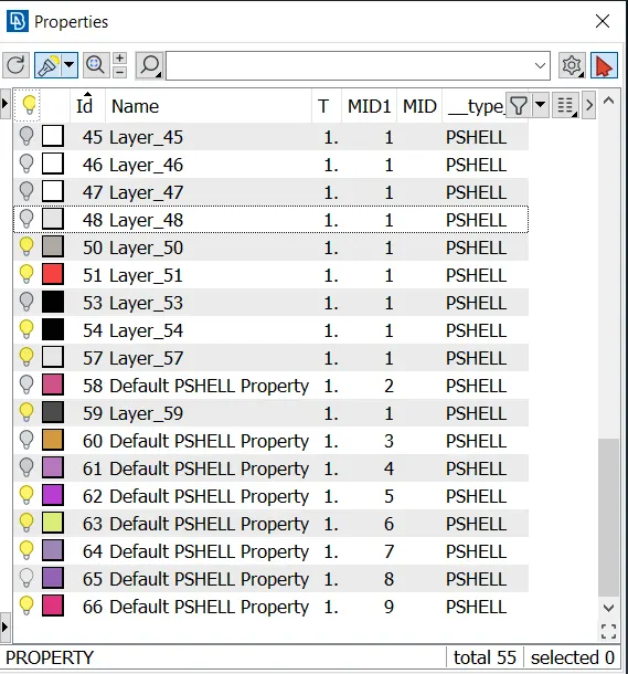
fig : Default PIDs
2. The PIDs can be created or assigned to the particular components by isolating . The unwanted PIDs can be compressed inorder to delete them .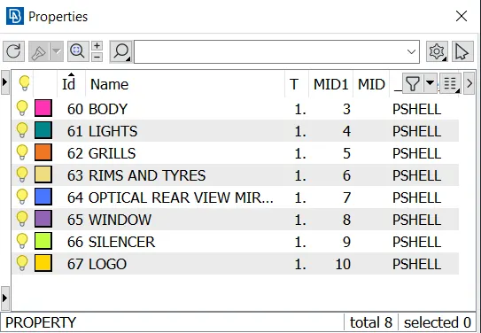
fig : PIDs renamed
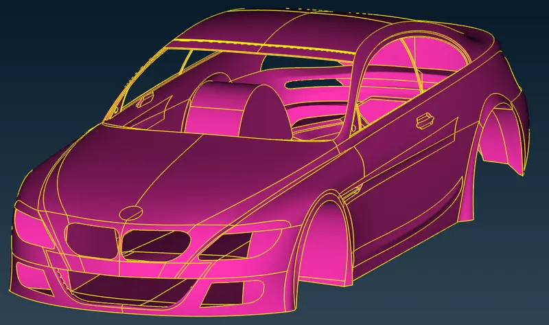
3. BODY PID :
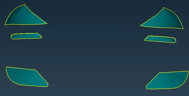
LIGHTS PID :
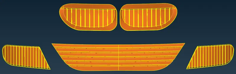
GRILLS PID :
RIMS AND TYRES PID :
Optical Rear view mirror PID :
WINDOWS PID :
SILENCER PID :
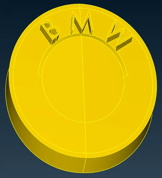
LOGO :
- SURFACE MESHING :
1. Before initiating the mesh quality criteria , mesh parameters and target lengths must be initiated in respective order inorder to create better quality mesh elements.
2. The off elements must be taken care of after the meshing process by using mesh improvement tools such as MOVE , IMPROVE, SPLIT etc .
3. Target lengths for the different parts of a model are as follow:
Body - 3 mm
Lights - 4 mm
Grills - 1 mm
Rims and Tyres - 2 mm
Optical Rear view mirror - 2 mm
Window - 2 mm
Silencer - 3 mm
Logo - 1 mm
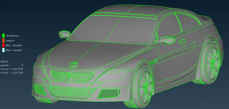
fig : MESHED model without the off elements - SYMMETRY CREATION :
1. Perform symmetry under transform option to create a exact same opposite body of the car to create a full body car. By selecting entities in the copy option the three point symmetry can be performed .
2. After creation of symmetry topo error must be checked once again.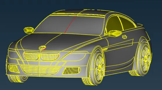
fig : Single con error after symmetry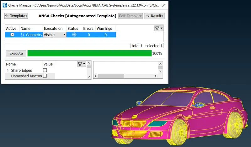
fig : FINAL topo check after symmetry - WIND TUNNEL CREATION AND MESHING :
1. Few standards must be followed inorder to create a wind tunnel i.e.
The wind tunnel dimmensions are as followed :
car model: 1300mm .................. (x)
Front surface distance(from reference points): 5854mm .................. (4x)
Back surface distance(from reference points): 8410mm .................. (6x)
Top surface distance(from reference points): 4275mm .................. (3x)
2. After calculating the wind tunnel dimensions appropriately , we can create the wind tunnel accurately with help of RELATIVE options [i.e TOPO DECK > POINTS > RELATIVE] which helps in creating a point relative to an already selected point in either x,y or z direction.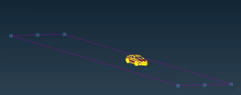
fig : Bottom surface created using RELATIVE option and CURVES
3. The OFFSET option canbe used to project the bottom surface to create the top surface and new faces can be created using coons or fitted option.
4. The PIDs to the wind tunnel must be assigned accordingly.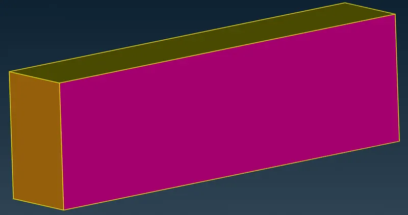
fig : wind tunnel
5. Finally after the creation of wind tunnel the surface meshing of it can be done for the external aerodynamic analysis of the car .
6. For meshing we need to apply surface meshing depending on the mesh length near the car and regions far away from it i.e. as we are closer to the car, we expect to have a finner mesh and as we move away from the car, we expect to have a coarser mesh.
7. Therefore we need to apply different mesh lengths at the bottom and top wind tunnel surfaces as a reason creation of variable length on the sides of the wind tunnel.
Target length of top surface = 100mm
Target length of bottom surface = 20mm
8. For variable length we can use SPACING option [i.e. MESH DECK > PERIMETERS > SPACING] .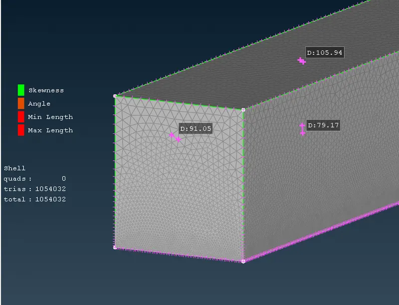
fig : meshed wind tunnel -
RESULT :
1. BODY - 3 mm :- Target Length = 3 mm
- Minimum Length = 1 mm
- Maximum Length = 5 mm
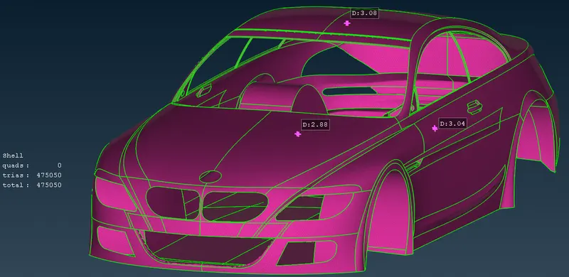
2. LIGHTS - 4 mm :
- Target Length = 4 mm
- Minimum Length = 3 mm
- Maximum Length = 5 mm
3. GRILLS - 1 mm : - Target Length = 1 mm
- Minimum Length = 0.3 mm
- Maximum Length = 2 mm
4. RIMS AND TYRES - 2 mm : - Target Length = 2 mm
- Minimum Length = 1 mm
- Maximum Length = 3 mm
5. OPTICAL REAR VIEW MIRROR - 2 mm : - Target Length = 2 mm
- Minimum Length = 1 mm
- Maximum Length = 3 mm
6. WINDOWS - 2 mm : - Target Length = 2 mm
- Minimum Length = 1 mm
- Maximum Length = 3 mm
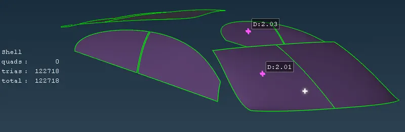
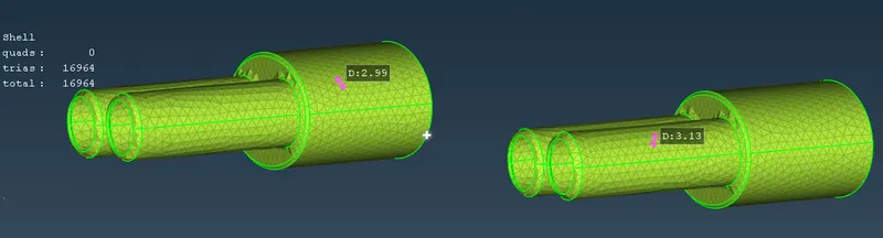
7. SILENCER - 3 mm : - Target Length = 3 mm
- Minimum Length = 1 mm
- Maximum Length = 5 mm
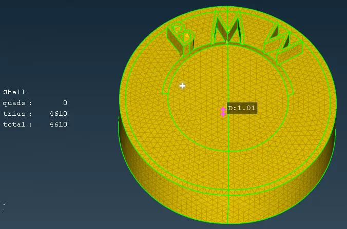
8. LOGO - 1 mm : - Target Length = 1 mm
- Minimum Length = 0.4 mm
- Maximum Length = 2 mm
9. WIND TUNNEL :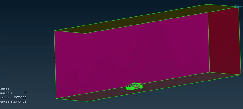
LEARNING OUTCOME :
1. ANSA GUI , different selection techniques and visibility tools.
2. Advanced Topology cleanup to define volumes. Variable Surface meshing part by part .
- 3. Symmetry operations for surface and mesh elements.
- 4. Wind tunnel creation and CFD Meshing of it.
CONCLUSION :
Adjacent component with different mesh length size tend to give errors at the contact regions , therefore mesh ranges can be given to avoid erasing of mesh.
GOOGLE DRIVE LINK :
https://drive.google.com/file/d/1NZngdypSvJVsYhlfw7tCNBX-i4oqDUQI/view?usp=sharing