Week 2 Challenge : Surface meshing on a Pressure valve
SURFACE MESHING ON A PRESSURE VALVE
AIM: To Triangular mesh the pressure valve of different target lengths ie 1mm, 3mm and 5mm after thorough verification of geometrical errors and performing the topological cleanup.
PROCEDURE:
1. Import the geometry in ANSA software.
2. After importing the geometry , topological diagnosis need to be done in check manager deck [ie CHECKS>GEOMETRY>EXECUTE] for any errors such as unchecked faces, collapsed cons, triple cons, single cons, needle faces, cracks, overlap faces, etc.
Fig: checks manager Fig: single cons error in wire frame mode
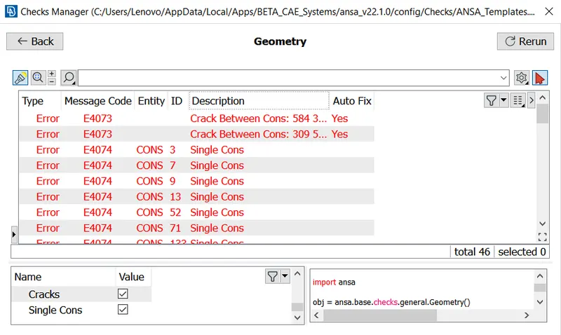
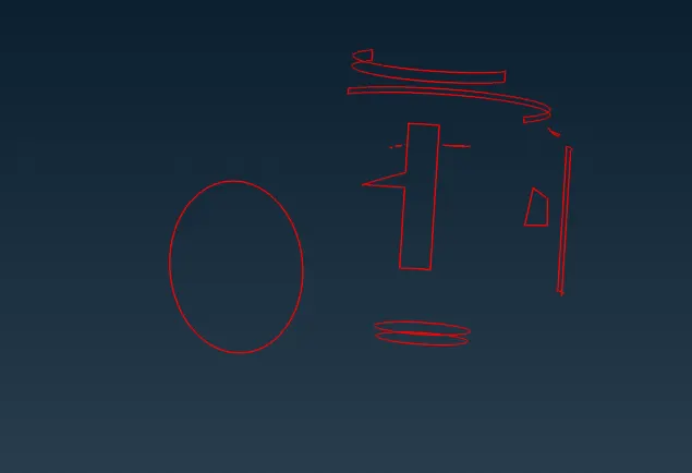
3. After diagnosis of the geometry the single cons errors need to be solved either by creating new surfaces or by filling the open gaps. New surfaces can be created in the topo deck [ie TOPO>FACES>NEW] or in some cases gap can be filled in topo deck [ie TOPO>CONS>FILLHOLE] by providing required parameters.
4. After the creation of new surfaces and filling of gaps , small surfaces need to be eliminated by selecting the CUT option as it may interfere during the meshing process.
Fig: cleaned geometry
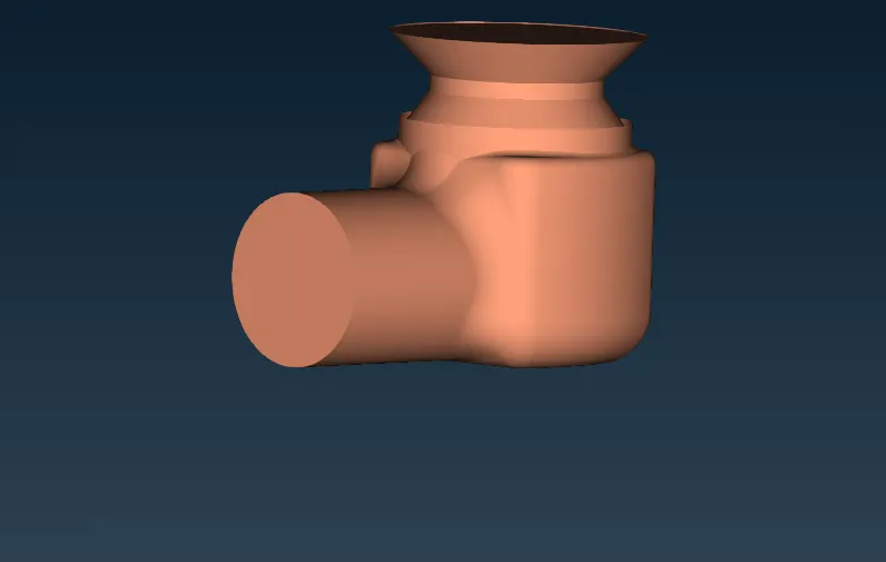
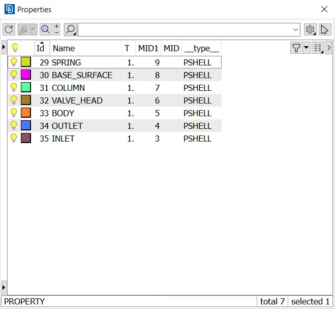
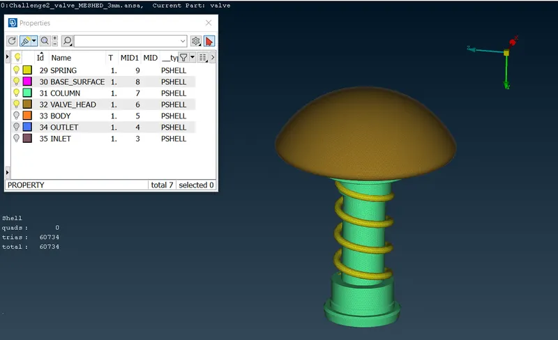
5. After thorough topological cleanup , the properties ID (PID) in property manager [ie Properties > New > PSHELL > PSHELL] are created inorder to identify every surface and named as inlet, outlet, body, spring, base surface, valve head, and column accordingly .
Fig: PID deck Fig: PID of pressure valve
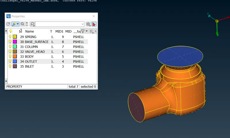
6. After the geometrical cleanup and creation of PID now meshing is done in the meshing deck firstly by specifying the length parameters in both perimeters and macros [ie MESH > Perimeters/Macros> Length] then specifying the mesh and quality criteria accordingly for 1mm , 3mm and 5mm mesh target lengths.
For Ex for 3mm : The max and min length need to set in both mesh parameter and quality criteria deck.
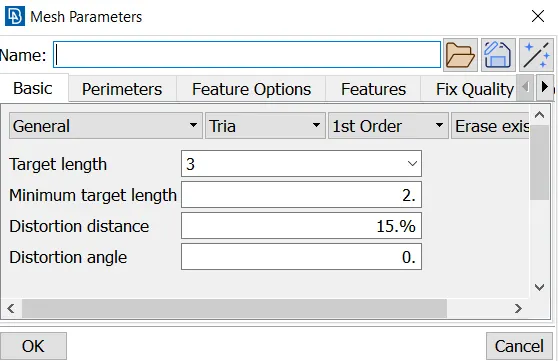
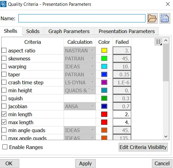
7. Finally after everything is set and verfied, create the surface mesh by using spot mesh algorithm [ie MESH > Mesh Generations > Spot Mesh] or any other algorithm available by selecting individual PID surfaces.
LEARNING OUTCOME:
1. GUI interface , selection and visibility tools in ANSA software.
2. Three main process in this challenge is topo cleanup , PID creation for each part and meshing.
3. In topo cleanup different types of errors ,diagnosis and resolution of geometry was introduced.
4. PID creation and assingment for different parts of the pressure valve.
5. 2D surface Meshing with the appropriate mesh parameters and quality criteria.
RESULT:
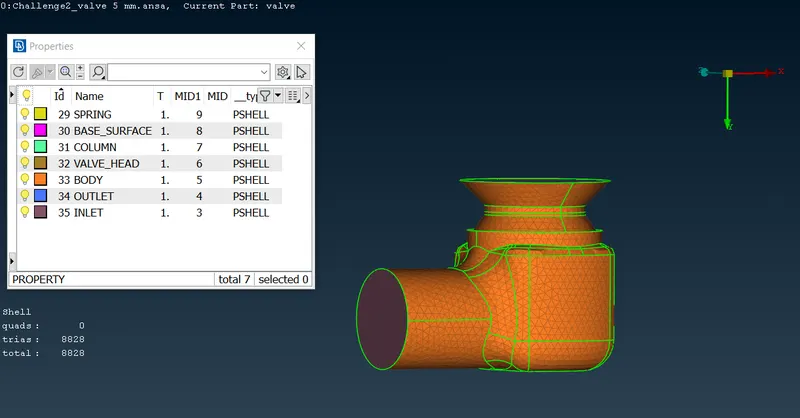
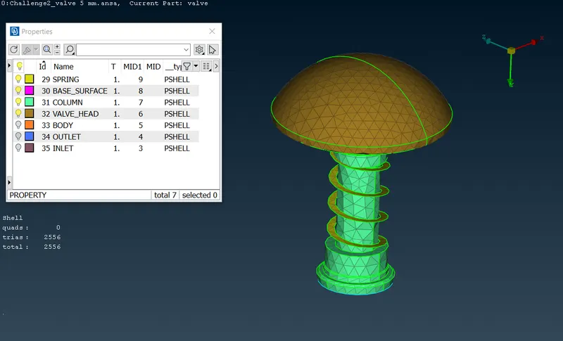
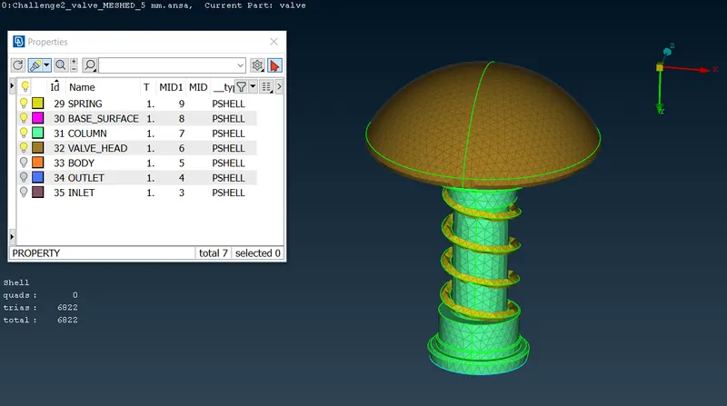
CASE 1 : MESH TARGET LENGTH = 5mm
CASE 2 : MESH TARGET LENGTH = 3mm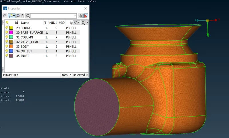
CASE 3 : MESH TARGET LENGTH = 1mm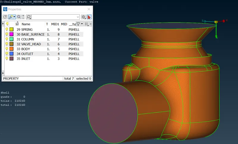
CONCLUSION:
1. 2D Surface meshing is done in three different cases using tria element type and target mesh length of 5mm, 3mm and 1mm.
2. Case 1 with a mesh length of 5 mm has a total of 8828 elements, Case 2 with a mesh length of 3 mm has a total of 23884 elements, and Case 3 with a mesh length of 1 mm has a total of 210260 elements respectively.Therefore as the target length decreases from 5mm to 1mm the no of elements increases.
3. It is also observed that as the target length decreases from 5mm to 1mm the accuracy in the mesh also increases immensly especially in the spring.
4. Therefore the same target mesh length for the entire PID surface does not suit for case 1 and 2 as the mesh length is larger than the spring diameter and valve head PID surface curvatures. But for Case 3 with mesh length 1mm is suitable for the entire PID.Hence mesh length initialisation is a crucial part in assignment to various PIDs.
5. Hence the target mesh length should be varied as per the PID surface accordingly in order to maintain the surface mesh accuracy.