Week 3 - 2D meshing for Sheet metal
2D MESHING FOR SHEET METAL
PROBLEM STATEMENT :
For the given Hood model, Take the mid surface for all the components after checking the geometrical errors and mesh the mid surface with the given element Quality criteria.
AIM :
1. To perform the topological and geometrical cleanup of the given sheet metal components.
2. To generate mid surface of the components and PID creation of the surface.
3. To set the quality criteria for the shell elements and generate shell elements on the midsurface with proper mesh flow ie mesh improvement .
Given Element Quality criteria :
|
S.No |
Quality Criteria |
Value |
|
1 |
Target/Average length |
5 |
|
2 |
Minimum Length |
2 |
|
3 |
Maximum Length |
7 |
|
4 |
Aspect |
3 |
|
5 |
Warpage |
15 |
|
6 |
Skewness |
45 |
|
7 |
Jacobian |
0.7 |
|
8 |
Minimum Quad Angle |
45 |
|
9 |
Maximum Quad Angle |
135 |
|
10 |
Minimum Tria Angle |
30 |
|
11 |
Maximum Tria Angle |
120 |
|
10 |
Tria Percentage |
15 |
PROCEDURE :
1. GEOMETRY CLEANUP .
2. MID SURFACE AND PID CREATION .
3. ASSIGNING ELEMENTAL QUALITY CRITERIA .
4. MESH GENERATION AND MESH IMPROVEMENTS .
- GEOMETRY CLEANUP :
1. Firstly import the CAD model to ANSA . After importing the model, initially we have to thoroughly analyze the geometry. When a CAD model is brought into ANSA, potential geometrical errors may arise, such as missing or distorted surfaces, intersecting surfaces, etc., caused by format conversion or inherent issues in the model. Consequently, it becomes vital to rectify these errors before commencing the meshing process.
Given CAD model in ENT mode and WIRE frame mode
2. Since there are 5 components in the hood ie inner panel, outer panel , right and left hinges and latch so each and every component must be diagnosed and rectified of topo errors i.e geometry check and inorder to guarantee the proper connection of all surfaces, the Faces>Topo tool is applied individually to each component's edges.
Fig : Outer panel Fig : Inner panel
Fig : Left Hinge Fig : Right Hinge Fig : Latch
3. The geometrical errors can be diagnosed in the checks manager [i.e. CHECKS>CHECK MANAGER>GEOMETRY ] where different topological error such as (single cons, needle face, unchecked face, overlapped face, cracks etc) can be rectified using autofix or through manual resolution of errors .
Fig : Check manager ( 51 topo errors )
4. After the diagnosis of topo errors the cons resolutions must be done inorder to check the actual geometry of the sheet metal component which can be done in Fine option in topo module [i.e.TOPO>AUXILIARIES>FINE] or by using length tool in mesh module [i.e.MESH>PERIMETERS>LENGTH>PERIMETERS AND MACROS].
5. Also the orientation correction must be checked using orient tool [ i.e. TOPO>FACES>ORIENT ] as problems may arise during meshing phase . It is generally observed that the given surface is with mixed yellow and grey color, which shows a mixed normal direction on the surface. So, inorder to correct it as either yellow or grey on the outer surfaces to either grey(+ve) or yellow(-ve) Orient tool is used . - MIDSURFACE AND PID CREATION :
1. After thorough geometry check and cons resolution the mid surface must be generated inorder to perform meshing . Midsurface can be generated using two types of methods ie either automatic midsurface generation using skin option [i.e. TOPO>FACES>MIDSURFACE>SKIN] or by doing manually using offset option [i.e. TOPO>FACES>OFFSET] .
2. Inorder to use manual offset option firstly we have to measure the thickness of all the five components individually. As the hood is a sheet metal component the thickness will be even throughout a particular component . It is noted that inner and outer panel is of 0.75mm thickness and the hinges and latches are of 1.2mm thickness.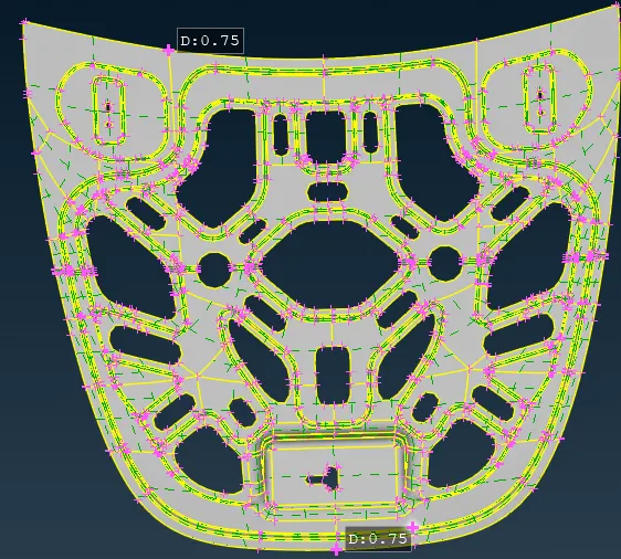
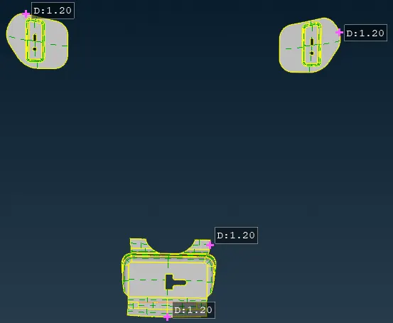
Fig : Inner panel 0.75mm thickness Fig : Hinges and Latch of 1.2mm thickness
3. After measuring the thickness of the components, half of the thickness need to be assigned inorder to obtain the midsurface while orienting in a particular direction using offset option [i.e.TOPO>FACES>OFFSET] .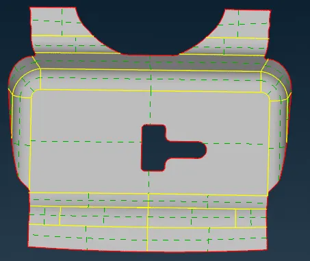
Fig : Midsurface of latch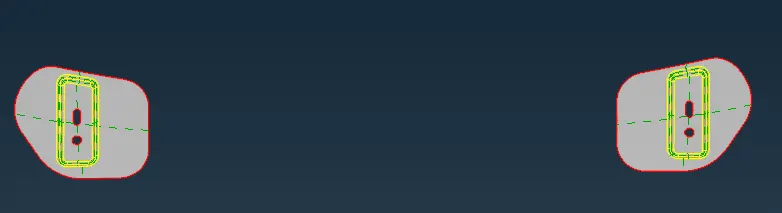
Fig : Midsurface of Hinges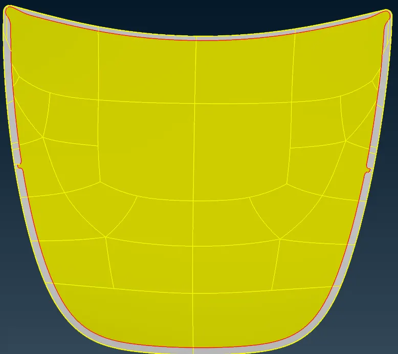
Fig : Midsurafce of outer panel
4. Automidsurface generation method was used to obtain the midsurface of inner panel. When utilizing the Skin feature for midsurfacing, it had to be made sure that not to select the 'Delete original faces' option in the options list . Failing to do so would had resulted in the removal of the parent object when generating the mid surface.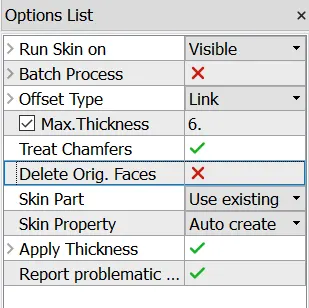
Fig : Option list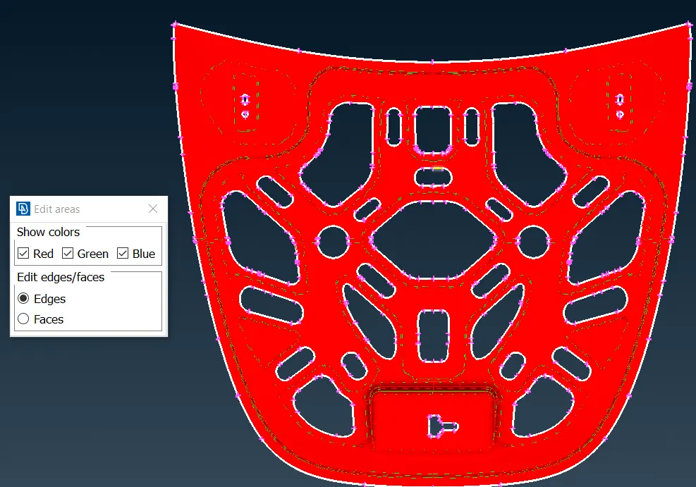
Fig : Automid prompt for inner panel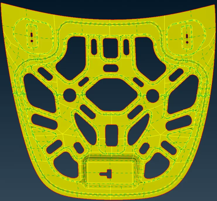
Fig : Midsurface of inner panel
5. Property IDs (PID) must be assigned to the extracted midsurfaces by creating new shell property known as pshell [i.e.PROPERTIES>NEW>PSHELL ]. - MESHING AND MESH IMPROVEMENT :
1. After Midsurfacing and PID creation the quality criteria [i.e. Utilities>Criteria] and mesh parameter [i.e. Utilities>Mesh parameters ] must be assigned inorder to proceed with meshing process in Utilities tab.
Also every area of the components must be checked where the elements might fail for minimum elemental length and altered.
2. In mesh parameters the settings for target length, minimum element length, and maximum element length are adjusted to 5, 2, and 7 respectively, while all remaining parameters are retained as their defaults for both mixed and 1st order elements. And also the given quality criteria must be assigned .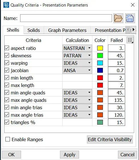
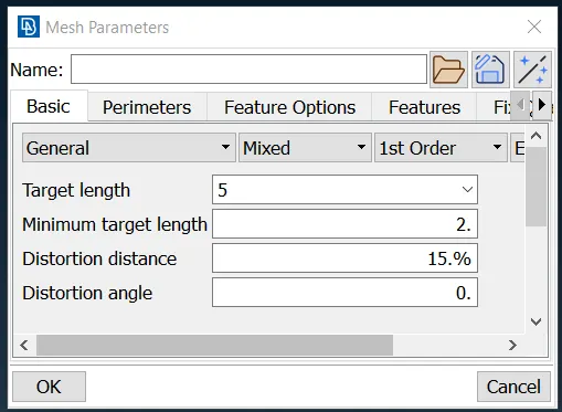
Fig : Quality criteria Fig : Mesh parameters
3. After assigning quality criteria and mesh parameters , the meshing process can be proceeded in the mesh module by setting the perimeters length [i.e. MESH>PERIMETERS>LENGTH ] and macros length respectively and best mesh algorithm [i.e. MESH>MESH_GENERATION>BEST ]can be chosen for meshing .
While meshing care must be taken of the off elements which fail in the quality criteria and must be rectified .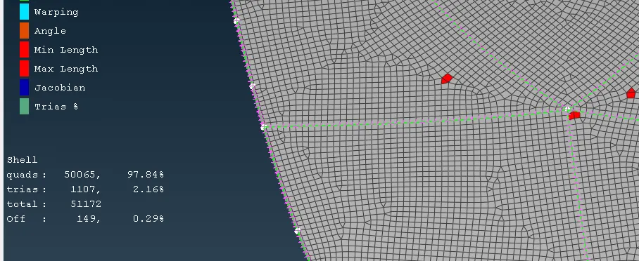
Fig : Off elements
4. The off elements can be rectified either using improve option
[i.e. MESH>SHELL_MESH>IMPROVE>FIX_QUALITY ] or by using reconstruction option
[i.e. MESH>SHELL_MESH>RECONSTRUCTION] .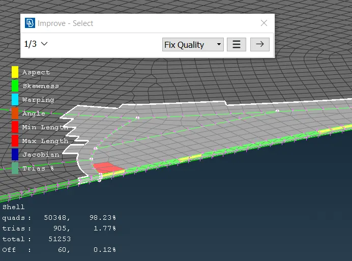
Fig : OFF elements removal
5. After meshing proper flow and mesh improvements must be taken careof that is there must be no roatating quads and tria elements concentration must be reduced as much as it is possible , which can be done using Elements>split,swap,join options . Also after modifying the mesh Smooth option can be used to smooth the mesh flow .
RESULT :
1. MESH OF OUTER PANEL : 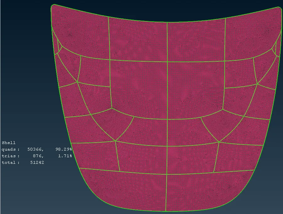
2. MESH OF INNER PANEL : 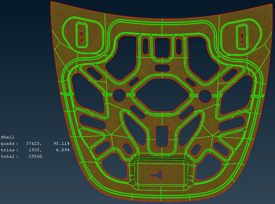
3. MESH OF HINGES :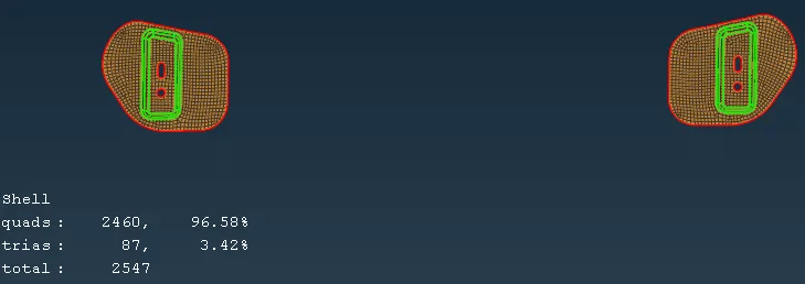
4. MESH OF LATCH :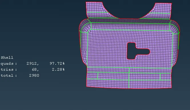
CONCLUSION :
1. Extracted the Midsurface after proper topo cleanup of the given car hood components.
2. 2D mesh generation of the given car hood components under given quality criteria.
LEARNING OUTCOME :
1. ANSA GUI and basic tools .
2. Topo or geometry cleanup.
3. Mid surface extraction and assignning thickness to midsurface .
4. PID creation .
4. 2D Mesh generation and mesh improvement .
Google drive :
https://drive.google.com/file/d/1N-sZBgW4byU47nj-W6dEhmPDnmDX1519/view?usp=sharing