Week 3 Challenge : CFD meshing on Turbocharger
CFD MESHING ON A TURBOCHARGER
PROBLEM STATEMENT :
For the given model, check for the geometrical errors to make appropriate volumes. Create and assign PIDs then perform surface mesh with the given target lengths as per PIDs.
- Blade stage-1 = 1 mm
- Blade stage-2 = 1 mm
- Impeller = 2 mm
- Shaft rotor = 1 mm
- Turbo casing = 5 mm
- Compressor casing = 5 mm
- Inlet casing cover = 5 mm
AIM :
To perform the surface and volumetric mesh of the turbocharger after rectifying all the geometrical, topological and meshing errors with the given specifications i.e.
- Blade stage-1 = 1 mm
- Blade stage-2 = 1 mm
- Impeller = 2 mm
- Shaft rotor = 1 mm
- Turbo casing = 5 mm
- Compressor casing = 5 mm
- Inlet casing cover = 5 mm
PROCEDURE :
1. Import the given geometry to ANSA software.
2. Firstly analyse the given geometry for any topological or geometrical errors in the topo deck.
3. After thorough topo cleanup , we proceed with the renaming or creation of the Property IDs i.e. PIDs for different components in the property manager.
4. After assigning of the PID , surface meshing is done in the mesh deck.
5. Finally the volumetric meshing is done in the volumetric mesh deck.
- TOPOLOGICAL CLEANUP :
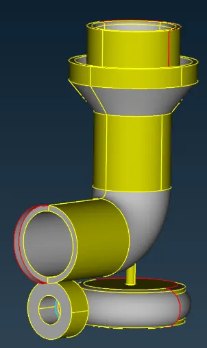
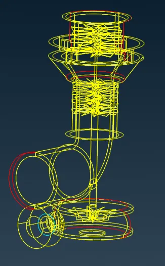
fig: given CAD model in ENT and WIRE frame mode respectively
1. Firstly perform the diagnosis of the geometry in the check manager for anykind of topo errors such as single cons, triple cons.
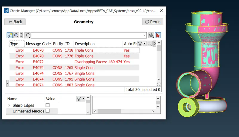
fig: checks manager
2. The errors present in the check manager can be resolved by using pick option part by part.
3. The glitches present in geometry is overlapping of surfaces which can removed using universal DELETE option by selecting the cross hatch of each entity. A thorough verfication must be done as there may be many overlapped surfaces present.
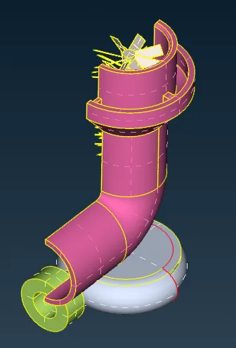
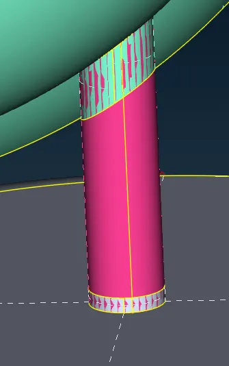
fig : overlapped surfaces fig: glitch
4. After clearing all the overlapped surfaces present ,the single cons (present as red color ) errors can be resolved by creating new surfaces or by fill hole option [i.e. TOPO>FACES>NEW or TOPO>CONS>FILLHOLE].
fig: single cons ( red color con) in wire frame mode
5. Intersect option [i.e. TOPO>FACES>INTERSECT] is used inorder to connect two groups of faces that penetrate each other. Triple cons error can be removed if formed.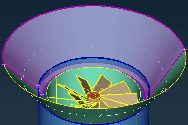
fig: Blade stage 2 intersect casing
6. Triple cons present in the geometry sometimes are errors other than warnings , so the errors must be resolved. The TOPO tool [i.e. TOPO>FACES>TOPO] is benefical in detecting the triple cons , if it converts the single cons to triple cons then there will a overlapped surface present which is to be resolved.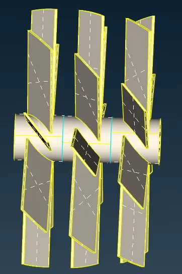
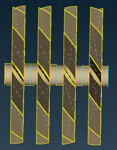
fig: triple cons (blue color con) error present in the blades section
7. Finally after cleaning up of the geometry , all the inlets and outlet need to be closed inorder to perform volumetric meshing.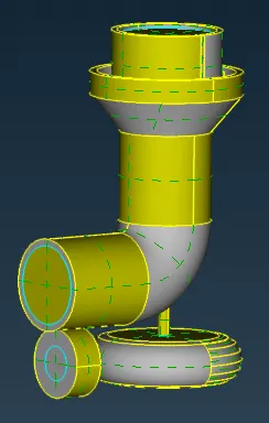
fig: Topo cleaned and closed turbocharger - PID CREATION :
1. Property IDs can be assigned in the property manager deck.
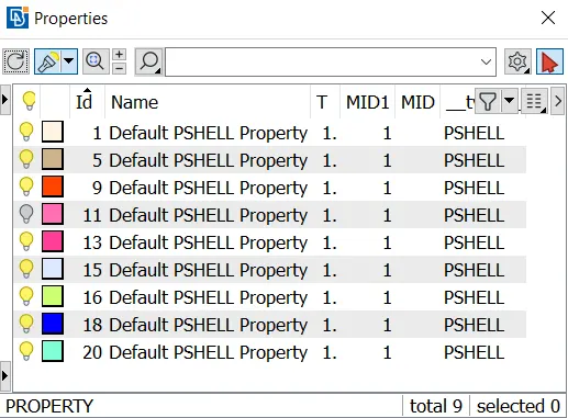
fig: default property manager
2. The predefined PIDs can be renamed and assigned to the respective entities by APPLY option [i.e. PROPERTIES>PID>APPLY] . New PIDs [i.e. PROPERTIES>NEW>PSHELL>PSHELL] can be created and then assigned to the entities .
3. The unwanted PID can deleted using compress or delete option.
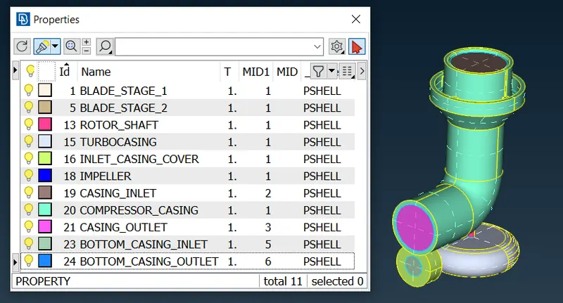
fig: PIDs of all the components - SURFACE MESHING :
1. After topological clean up and PID creation surface meshing should be done before performing volumetric mesh.
2. Individual surface meshing of components must be done as there are regions where the mesh has to be finner for better capturing of physics . Therefore variable mesh parameters, quality criteria and mesh lengths will be incorporated in the meshing process.
3. While entering the mesh length, the transition in mesh length between components with different mesh length tend to erase the adjacent mesh when they come in contact with eachother , therefore while entering the perimeter and macros [i.e.MESH>PERIMETERS>LENGTH>PERIMETER/MACROS] we need set a range from the bigger to smaller mesh length to avoid this .
4. Inorder to create a smooth transition between the mesh element of ajacent components , a boundary can be created using cut option [i.e. MESH>MACROS>CUT].
BLADE STAGE 1 SURFACE MESHING :
1. Target Length = 1 mm
2. Minimum Length = 0.5 mm
3. Maximum Length = 2 mm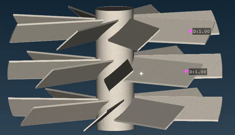
BLADE STAGE 2 SURFACE MESHING :
1. Target length = 1 mm
2. Minimum Length = 0.5 mm
3. Maximum Length = 2 mm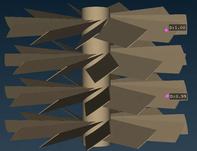
IMPELLER SURFACE MESHING :
1. Target length = 2 mm
2. Minimum length = 1 mm
3. Maximum length = 3 mm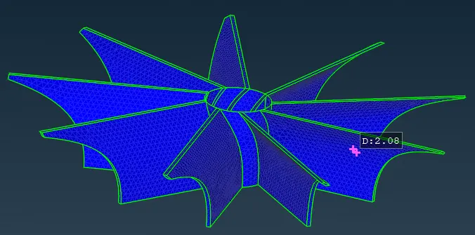
ROTOR SHAFT SURFACE MESHING :
1. Target length = 1 mm
2. Minimum length = 0.5 mm
3. Maximum length = 2 mm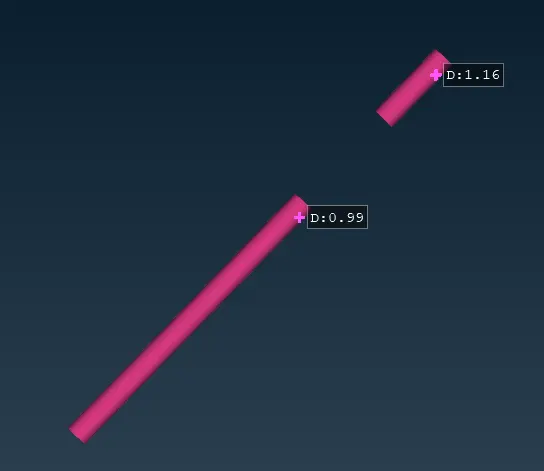
TURBO CASING SURFACE MESHING :
1. Target length = 5 mm
2. Minimum length = 3 mm
3. Maximum length = 7 mm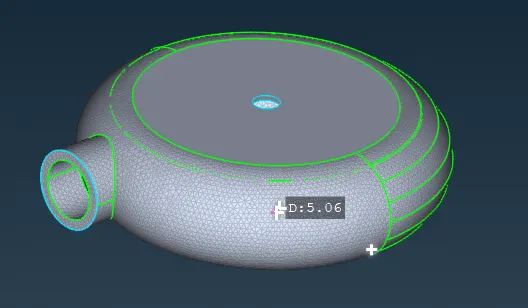
COMPRESSOR CASING MESHING :
1. Target length = 5 mm
2. Minimum length = 3 mm
3. Maximum length = 7 mm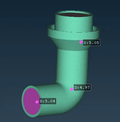
INLET CASING COVER MESHING :
1. Target length = 5 mm
2. Minimum length = 3 mm
3. Maximum length = 7 mm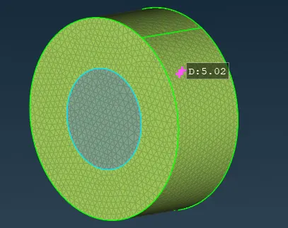
- VOLUMETRIC MESHING :
1. Finally after surface meshing we can perform volumetric meshing.
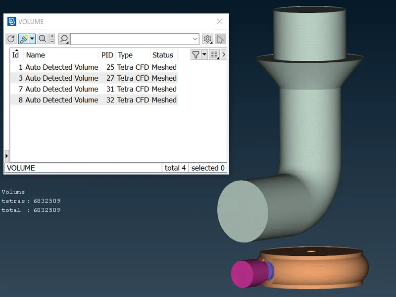
2. The define option [i.e. VMESH>VOLUMEs>DEFINE ] in volume mesh deck is used to define the database for meshing and to identify the various volumes present for the possible fluid flow. The unwanted outer thickness of the components can be deleted and only the necessary fluid flow volume can be kept.
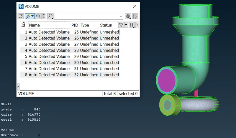
fig : Detected volumes present in the geometry
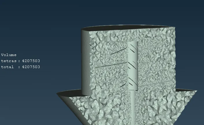
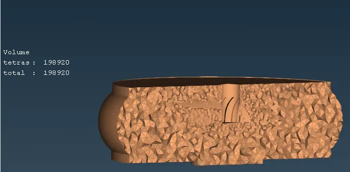
3. After the proper defining of volume , we can remesh each volume using TETRA CFD tool
[i.e. VMESH>UNSTRUCTURED MESH >TETRA CFD ]
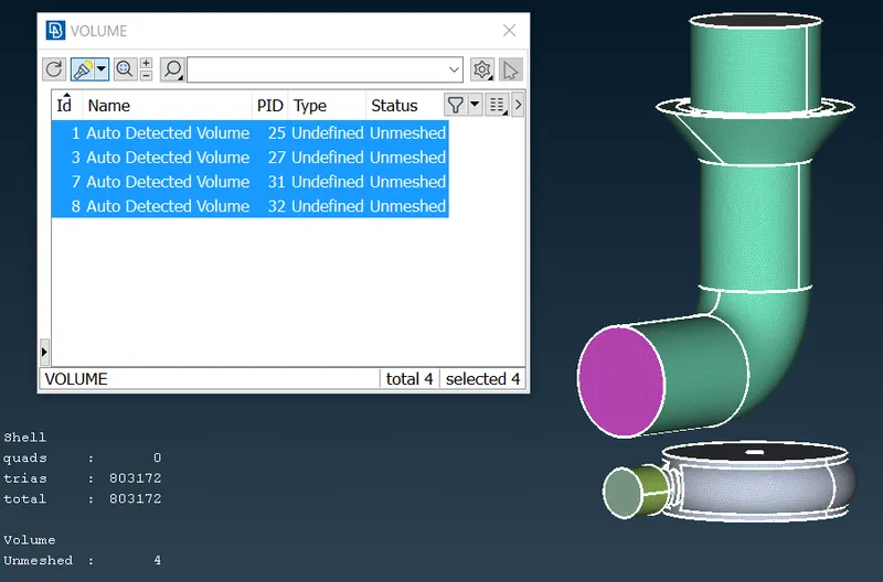
fig : TETRA CFD mesh volume for fluid flow region
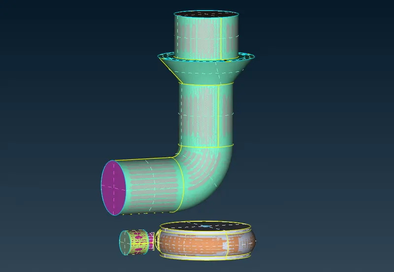
fig : Final volume mesh in topo mode
LEARNING OUTCOME :
1. ANSA GUI , different selection techniques and visibility tools.
2. Three main process before performing volumetric meshing i.e. topo cleanup , PID creation and surface meshing
3. Checking of geometry , solving the topo errors [ single cons , triple cons ] and deleting the overlapped or glitch surfaces inorder to improve the mesh quality and to avoid errors during volume meshing.
4. PID creation and assignment.
5. Surface meshing of individual components using variable length mesh parameters.
6. Identifying and creating volume only for the fluid region part and tools to create volumetric meshing.
RESULTS :
1. Geometrically cleaned and closed surface with proper PID :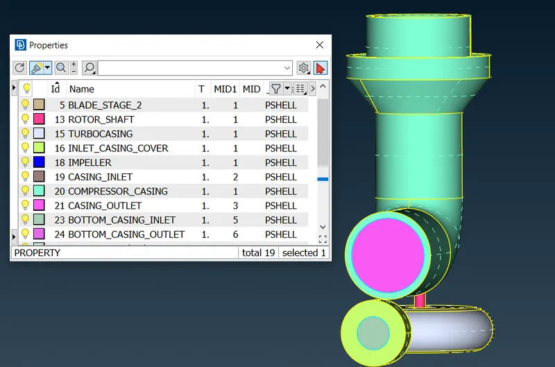
2. Surface mesh with variable mesh length parameters :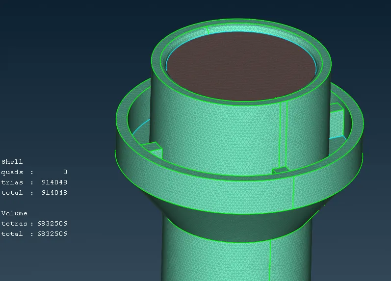
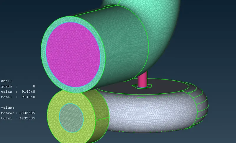
3. Volume mesh created for the fluid volume region :
CONCLUSION :
1. Volumetric mesh can be achieved only after proper geometry cleanup and surface mesh or else the geometry can give fatal errors while volume meshing.
2. Adjacent component with different mesh length size tend to give errors at the contact regions , therefore mesh ranges can be given to avoid erasing of mesh.
GOOGLE DRIVE LINK :
https://drive.google.com/file/d/1HIkA8HJuwZTRR3GxJpW6461C5BRKzC5y/view?usp=sharing