Week 4 Challenge : CFD Meshing for BMW car
CFD MESHING FOR BMW CAR:-
Objective-
- Do topo cleanup for BMW car
- Do 2D meshing, check quality criterias
- Use hidden mode to check failed meshes on quality criteria
- Use reconstruct option to view and clear failed meshes
- Do 3D Meshing for car
- Create a wind tunnel , either in 2D or 3D mesh depending on capacity of your system
Steps involved in complete process-
- Topo cleanup - topo cleanup is basically cleaning geometry by removing unwanted surfaces and solving triple and double cons
- Geometry is irregular in shape after we exported file to ansa. Irregular means surface irregularities , removing these is our first step
- Start with topo cleanup for eachh parts eg: tyres, grills, logos, windows, lights and batteries
- Use entity mode while working.
- Divide geometry into half as geometry is symmetric.
- Start with 2D meshing after topo cleanup
- Start with 3D meshing after 2D meshing
Original Geometry-
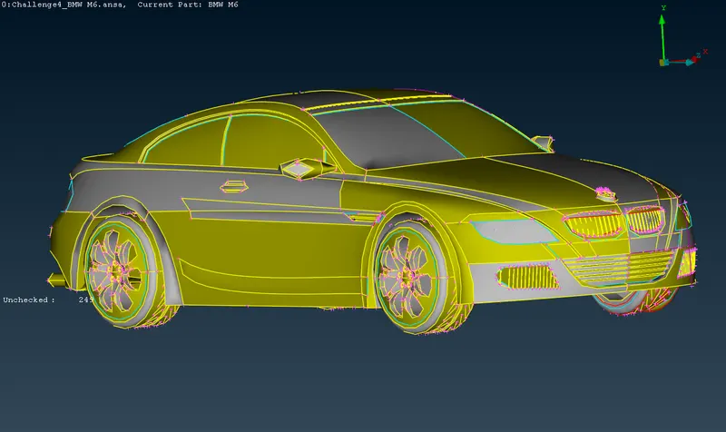
Original geometry first error is that cons are irregular, this is overcome by going into mesh tool
- Go to mesh tool and select length perimeter of 1mm for complete body, this will resolve all irregularities in cons alignment and body will appear in proper shape.
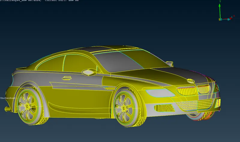
Divide Car into half
Problems in which there is symmetry on both sides it is prefered to divide body into half and then work on half body and then do symmetry to create other half of body withh available half body. This eases our work by half as there is only geometry to work with and the rest can be part can be created by symmetry tool.
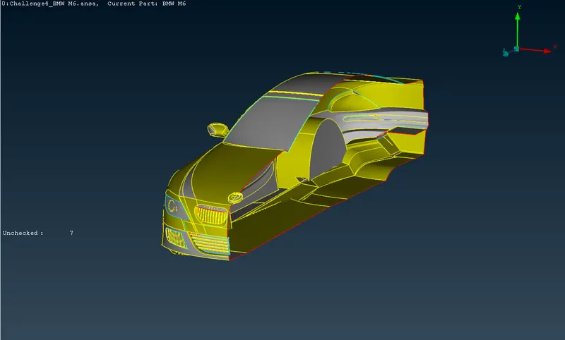
Parts to be solved
- Optical rear view mirrors
- Grills
- Tyres
- Body
- Lights
- LOGO
OPTICAL REAR VIEW MIRRORS
- Isolate side mirror by using Inot tool
- Remove all overlapping surface by identifying them using boolean operation tool
- Removing overlapped and extra surfaces will solve triple cons
- Use paste option to solve single cons if any.
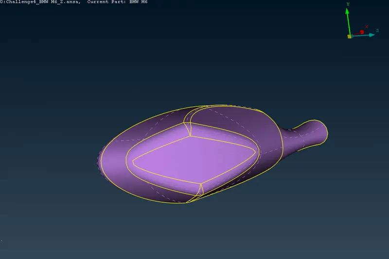
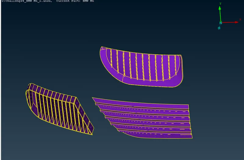
Grill
Steps involved
- Start with deleting extra surfaces
- There is large single con on front of grill, project that con on longitudnal grill you see, and after that delete upper part of longitudnal grill.
- Create hot points where there is requirement, so that it would be easy to create new surface with those hot points.
- Delete sharp edges from both corners of grills. Seperate sharp edges by creating cuts and then delete them
- Next step is to close grill geometry from inside or from back
- Use face tool to create new surfaces to close geometry.
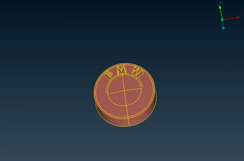
LOGO-
Steps involved
- Focus on two faces of logo, top & bottom.
- Start with bootom surface , delete overlapped surfaces. You will see logo hollow from bottom after deleting bottom surface
- Then go to top surface there you will another overlapped surface and delete it.
- Use not tool and hide top surface inside you will and extended surface attached with top surface inside logo, delete it.
- There is circular strip surface on top logo along boundary, delete that surface and use coons option to create a new surface at the gap created between boundary and middle part of logo.
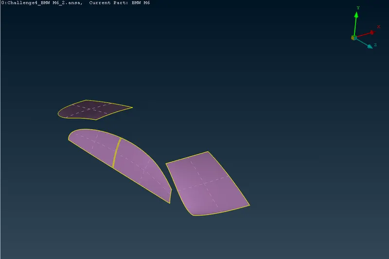
WINDOWS & LIGHTS-
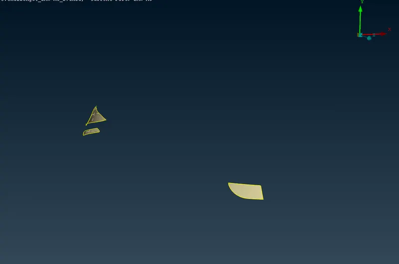
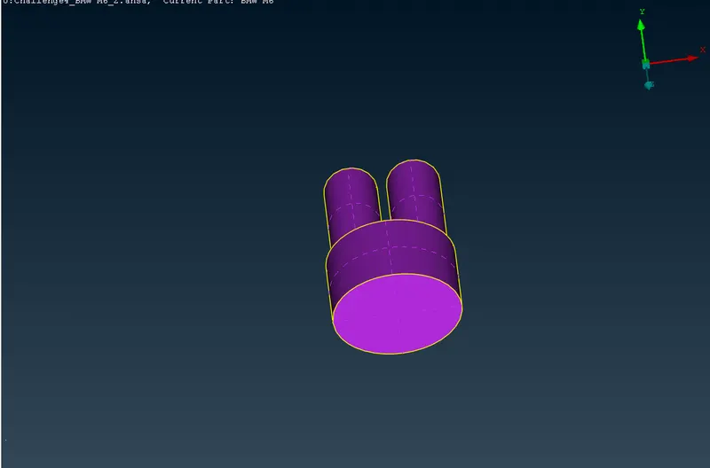
SILENCER
BODY-
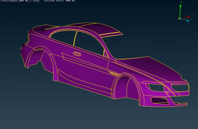
- Start with door handles, start by deleting overlapped surface as shown in image.
- There are some surface behind deleted surface, delete them too.
- After deleting them create new surface by selecting single cons.
Step 2- START 2D MESHING-
Target lengths for the different parts of a model are as follow:
- Body - 3 mm
- Lights - 4 mm
- Grills - 1 mm
- Rims and Tyres - 2 mm
- Optical Rear view mirror - 2 mm
- Window - 2 mm
- Silencer - 3 mm
- Logo - 1 mm
Start with meshing of smaller parts
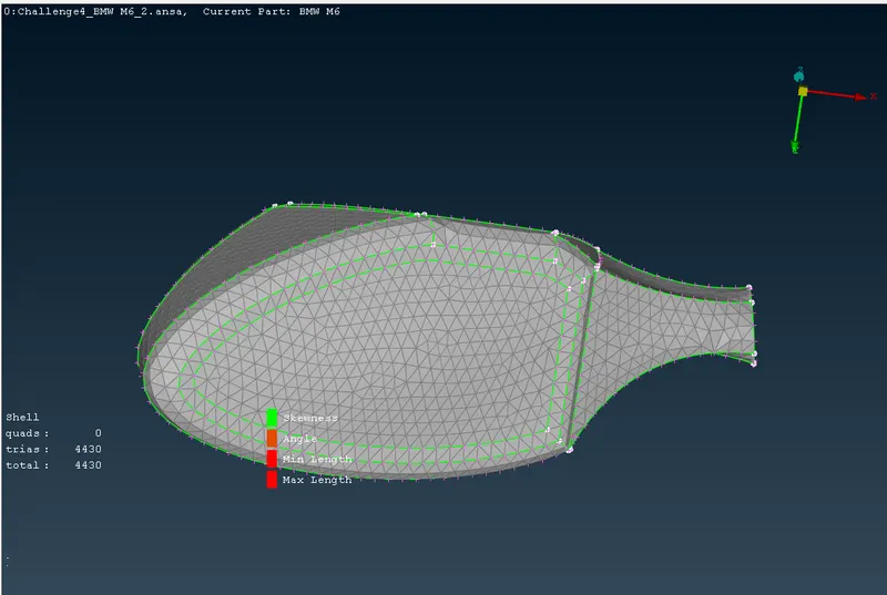
OPTICAL REAR VIEW MIRROR-
- Mesh length is 2mm
- After giving quality criterias, give length parameters and macros
- select length parameters and choose PID by doing right click and dragging cursor over PID. Then do middle click
- Dialogue box will appear, give mesh length 2mm and click ok
- Similar do for macros
- Then select spot mesh and choose visible mesh, you can see mesh on PID
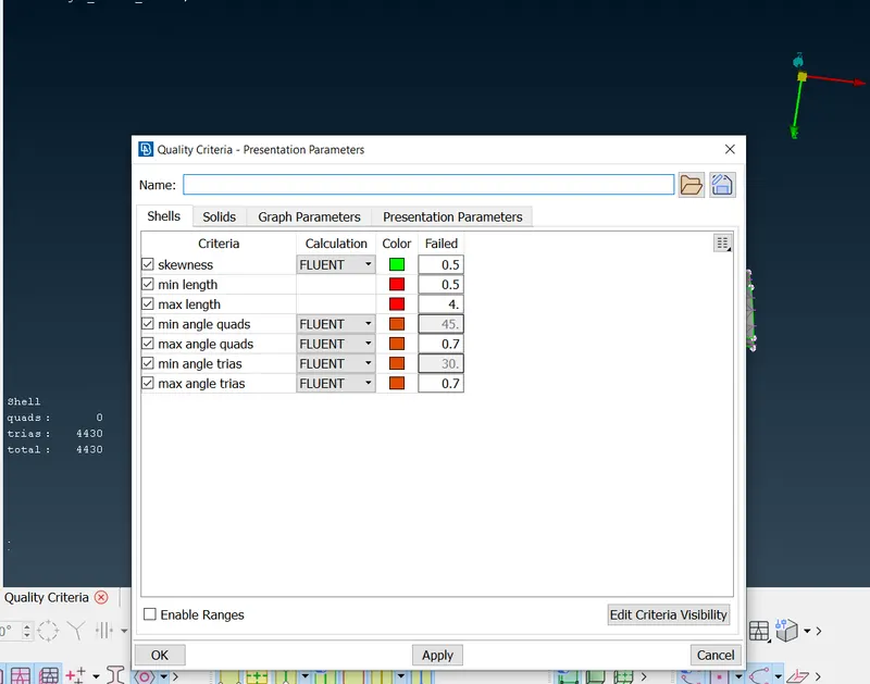
- In order to check if geometry is failing on quality criteria go to hidden mode and go to entity mode while using hidden mode.
- you will off elements. select reconstruct option and choose visible and execute reconstruct option. Reconstruct option will solve most of off elements and remaining off elements needs to be solved by findind why mesh is failing, mainly this happens due to formation of meshes smaller than specified criteria.
- Go to topo mode and use cut options to cut or recreate cons where mesh is failing.
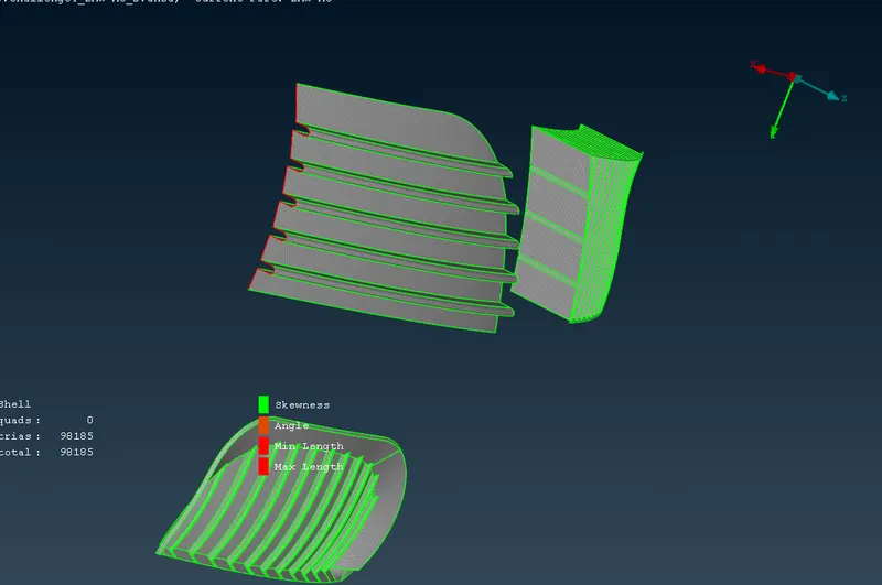
GRILLS Meshing-
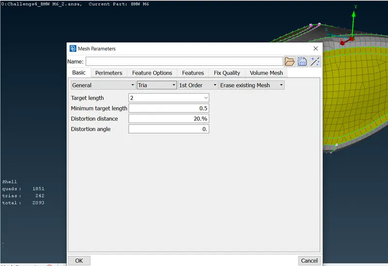
- Mesh length is 1 mm
- After giving quality criterias, give length parameters and macros
- select length parameters and choose PID by doing right click and dragging cursor over PID. Then do middle click
- Dialogue box will appear, give mesh length 1mm and click ok
- Similar do for macros
- Then select spot mesh and choose visible mesh, you can see mesh on PID
- In order to check if geometry is failing on quality criteria go to hidden mode and go to entity mode while using hidden mode.
- you will off elements. select reconstruct option and choose visible and execute reconstruct option. Reconstruct option will solve most of off elements and remaining off elements needs to be solved by findind why mesh is failing, mainly this happens due to formation of meshes smaller than specified criteria.
- Go to topo mode and use cut options to cut or recreate cons where mesh is failing.
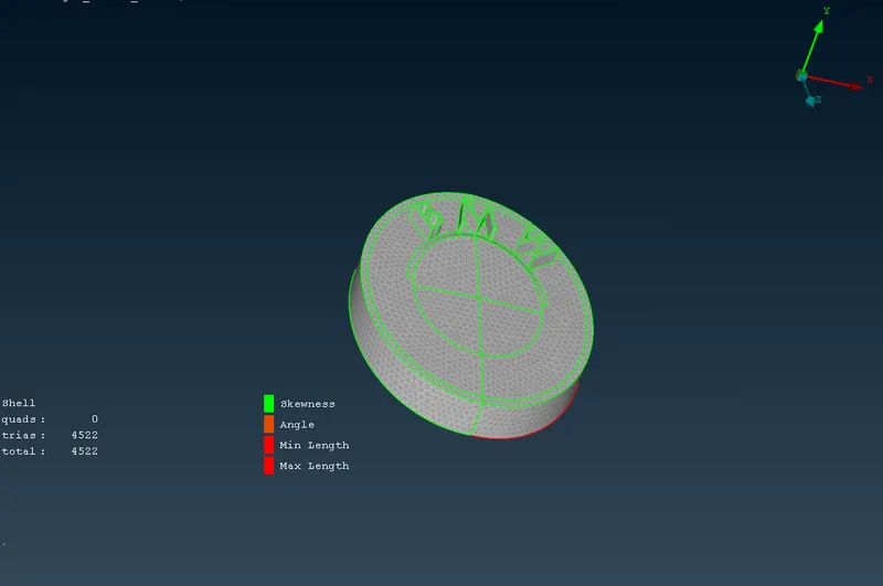
LOGO Meshing-
- Mesh length is 1mm
- After giving quality criterias, give length parameters and macros
- select length parameters and choose PID by doing right click and dragging cursor over PID. Then do middle click
- Dialogue box will appear, give mesh length 1mm and click ok
- Similar do for macros
- Then select spot mesh and choose visible mesh, you can see mesh on PID
- In order to check if geometry is failing on quality criteria go to hidden mode and go to entity mode while using hidden mode.
- you will off elements. select reconstruct option and choose visible and execute reconstruct option. Reconstruct option will solve most of off elements and remaining off elements needs to be solved by findind why mesh is failing, mainly this happens due to formation of meshes smaller than specified criteria.
- Go to topo mode and use cut options to cut or recreate cons where mesh is failing.
While using measure tool we find some lenghth on logo which are smaller than minimum length, so delete and create new surfaces on BMW so that minimum length problem is solved.
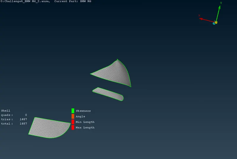
LIGHTS-
- Mesh length is 4mm
- After giving quality criterias, give length parameters and macros
- select length parameters and choose PID by doing right click and dragging cursor over PID. Then do middle click
- Dialogue box will appear, give mesh length 2mm and click ok
- Similar do for macros
- Then select spot mesh and choose visible mesh, you can see mesh on PID
- In order to check if geometry is failing on quality criteria go to hidden mode and go to entity mode while using hidden mode.
- you will off elements. select reconstruct option and choose visible and execute reconstruct option. Reconstruct option will solve most of off elements and remaining off elements needs to be solved by findind why mesh is failing, mainly this happens due to formation of meshes smaller than specified criteria.
- Go to topo mode and use cut options to cut or recreate cons where mesh is failing.
SILENCER Meshing-
- Mesh length is 3mm
- After giving quality criterias, give length parameters and macros
- select length parameters and choose PID by doing right click and dragging cursor over PID. Then do middle click
- Dialogue box will appear, give mesh length 2mm and click ok
- Similar do for macros
- Then select spot mesh and choose visible mesh, you can see mesh on PID
- In order to check if geometry is failing on quality criteria go to hidden mode and go to entity mode while using hidden mode.
- you will off elements. select reconstruct option and choose visible and execute reconstruct option. Reconstruct option will solve most of off elements and remaining off elements needs to be solved by findind why mesh is failing, mainly this happens due to formation of meshes smaller than specified criteria.
- Go to topo mode and use cut options to cut or recreate cons where mesh is failing.
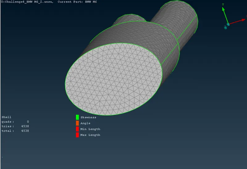
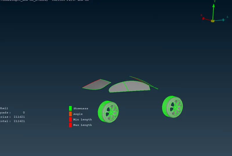
WINDOWS & Tyres Meshing-
- Mesh length is 2mm
- After giving quality criterias, give length parameters and macros
- select length parameters and choose PID by doing right click and dragging cursor over PID. Then do middle click
- Dialogue box will appear, give mesh length 2mm and click ok
- Similar do for macros
- Then select spot mesh and choose visible mesh, you can see mesh on PID
- In order to check if geometry is failing on quality criteria go to hidden mode and go to entity mode while using hidden mode.
- you will off elements. select reconstruct option and choose visible and execute reconstruct option. Reconstruct option will solve most of off elements and remaining off elements needs to be solved by findind why mesh is failing, mainly this happens due to formation of meshes smaller than specified criteria.
- Go to topo mode and use cut options to cut or recreate cons where mesh is failing.
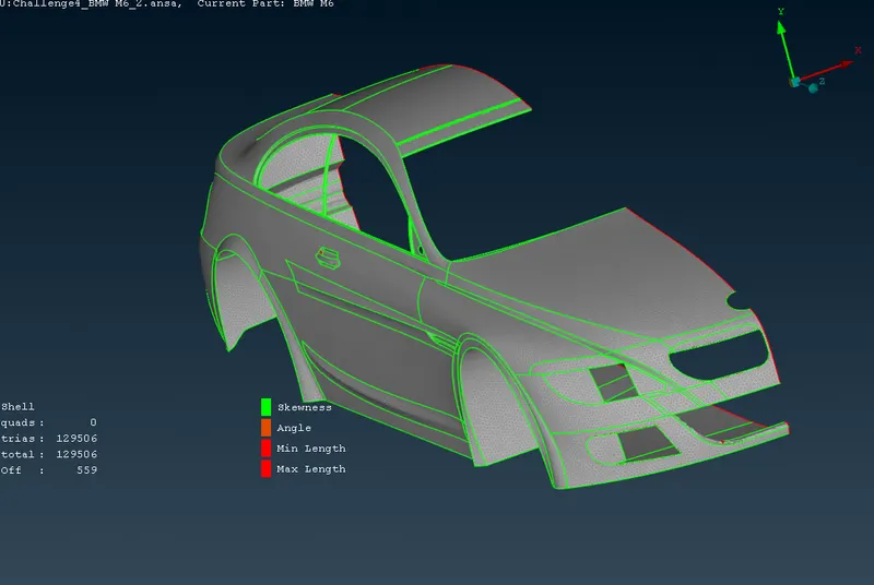
BODY-
There is a concept we have to follow while meshing body which is
- When there are PIDs with different mesh length and they are in direct contact with each other meshes on one PID disappear when me mesh other PID. This problem is overcomed by deleting perimeter lines that are in contact with other PID
- As we can see in image after selecting perimeters white color lines appeared on body, so we will delete perimetric lines that are in direct contact with other PIDs and then do right click and give mesh length
Steps for meshing
- Mesh length is 3mm
- After giving quality criterias, give length parameters and macros
- select length parameters and choose PID by doing right click and dragging cursor over PID. Then do middle click
- Dialogue box will appear, give mesh length 2mm and click ok
- Similar do for macros
- Then select spot mesh and choose visible mesh, you can see mesh on PID
- In order to check if geometry is failing on quality criteria go to hidden mode and go to entity mode while using hidden mode.
- you will off elements. select reconstruct option and choose visible and execute reconstruct option. Reconstruct option will solve most of off elements and remaining off elements needs to be solved by findind why mesh is failing, mainly this happens due to formation of meshes smaller than specified criteria.
- Go to topo mode and use cut options to cut or recreate cons where mesh is failing.
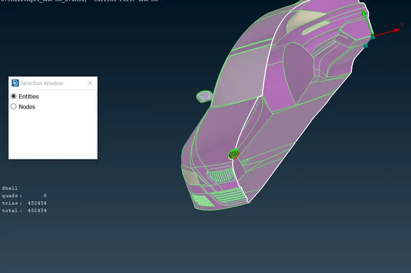
Step 3- CREATING OTHER HALF BODY USING SYMMETRY OPTION-
- Go to transform tool at top-right and choose copy option from transform tool.
- Choose Mirror 3 Points Plane from dropdown menu.
- There are options X1 X2 & X3, these box is required to be filled with coordinates
- choose three points as shown in image and those boxes will automatically take coordinates of those points after that do middle click and then another dialogue box will appear which will ask you to give offset distance as we dont want our copy to be created at an oaffset distance so leave that part and click ok
- Your symmetry body is created and geometry is now complete.
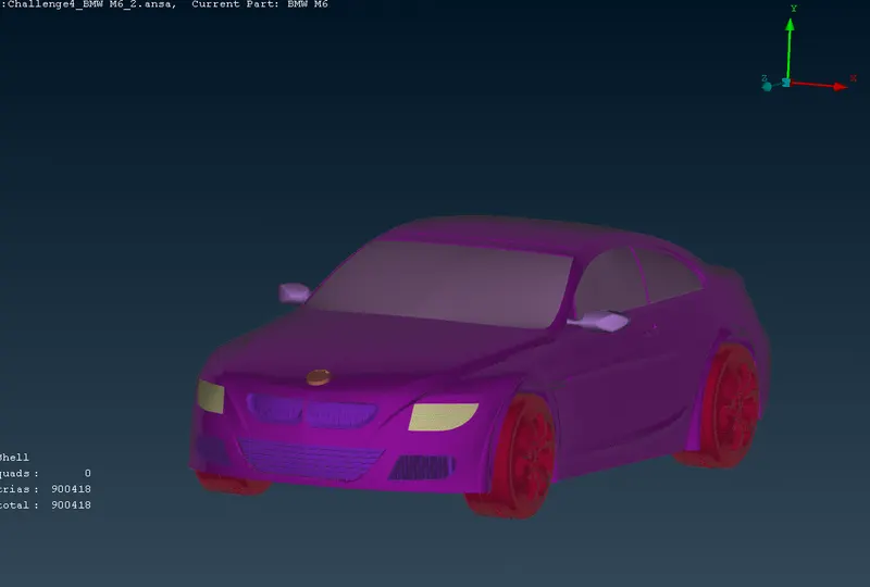
Step 4- WIND TUNNEL CREATION
We will create a wind tunnel around car
Measurment for wind tunnels are-
- Consider length of car as X
- Keep wind tunnel at 75mm distance from bottom of car
- Length of wind tunnel from front of car should be 4X, total length of tunnel in front is half length of car added to 4X length
- Length of wind tunnel from back of car should be 6X, total length of tunnel from rear side is half length of car added to 6X length
- Height of wind tunnel should be 3X
Steps Involved-
- Enable cons
- select relative points option from point tool and select a point in middle of car from bottom side
- A dialogue box will appear, see your coordinate axes, To create a point at bottom of car I will give 75mm with negative sign.
- With reference to that point create a point in front of car at distance 5820 in Z direction
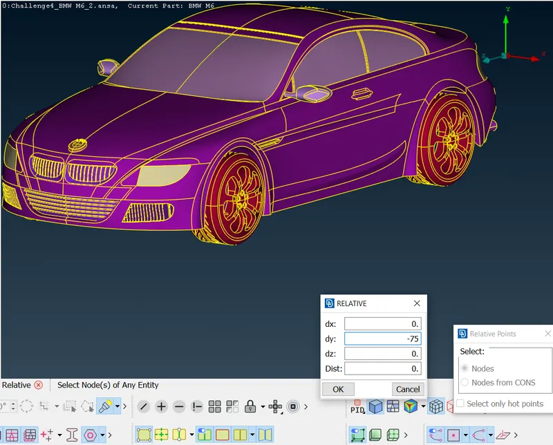
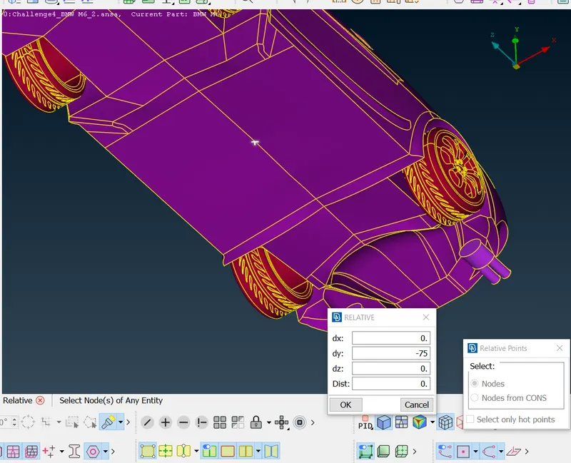
- After creating wind tunnel its time for meshing
- Top surface of wind tunnel would be meshed with 100mm mesh length
- Bottom surface would be meshed with 20mm mesh length
USE OF SPACING TOOL-
After creating top and bottom meshes it time for meshing sides of tunnel. In order to mesh sides of tunnel we will use spacing tool.
Basically what spacing tool does is it will vary mesh length from bottom to top, give min length as 20mm and max limit as 100mm and select factor of 1.1 and click ok.
Steps involved
- choose spacing tool give dmin and dlimit and spacing factor 1.1. spacing factor varies length from bottom top by factor of 1.1
- click on ok and select faces and do middle click.
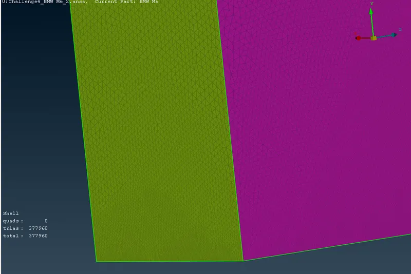
3D-MESHING TOOL-
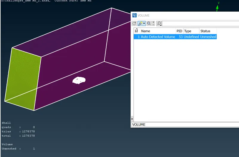
- Choose define option available in volumes tool and select wholedb(whole database) and click on ok.
- Volumes created for 3D meshing will appear in a dialogue box
CONCLUSION-
- Working on BMW model gave ideas about different meshing tools available in ANSA.
- Learned surface meshing and Geometry cleanup in much detailed manner. Challenges faced helped to understand tools better
- Learned how to use curve tool, how to create win tunnel with help of points and curves
- Learned about dimensions of wind tunnel, like what dimesnions to give based on model size
- Learned how to de meshing when there are different PIDs with different mesh length in contact with each other
- Advance topo-cleanup